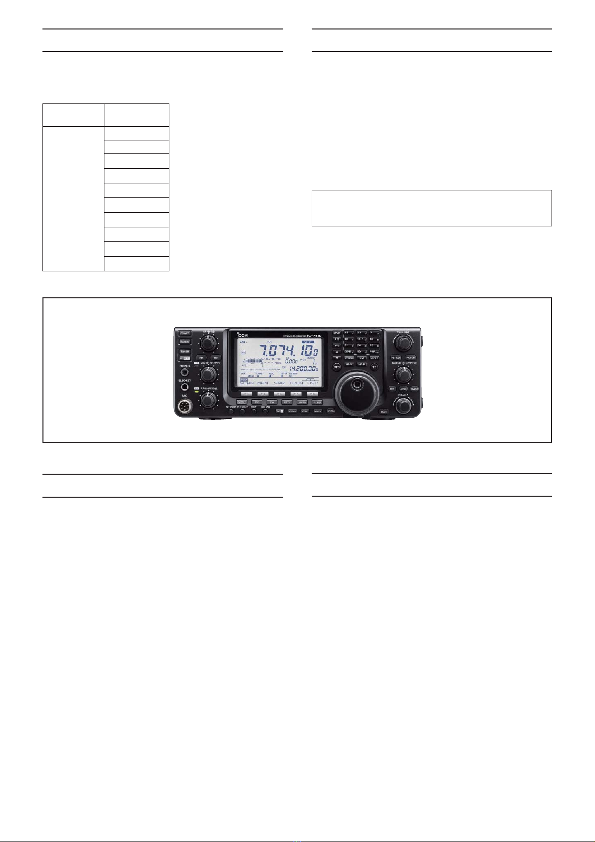
Icom IC-7410 User manual

S-14719XZ-C1
May. 2011
HF/50 MHz TRANSCEIVER

This service manual describes the latest technical
information for the IC-7410 HF/50 MHZTRANSCEIVER, at
the time of publication.
NEVER connect the transceiver to an AC outlet or to a DC
power supply that uses more than the specified voltage.
This will ruin the transceiver.
DO NOT expose the transceiver to rain, snow or any liquids.
DO NOT reverse the polarities of the power supply when
connecting the transceiver.
DO NOT apply an RF signal of more than 20 dBm (100 mW) to
the antenna connector. This could damage the transceiver’s
front-end.
To upgrade quality, any electrical or mechanical parts
and internal circuits are subject to change without notice
or obligation.
MODEL VERSION
IC-7410
USA
EUR
EUR-01
ITR
ESP
TPE
KOR
CHN
FRA
EXP
Be sure to include the following four points when ordering
replacement parts:
1. 10-digit Icom part number
2. Component name
3. Equipment model name and unit name
4. Quantity required
<ORDER EXAMPLE>
1110003491 S.IC TA31136FNG IC-7410 MAIN UNIT 5 pieces
8820001210 Screw 2438 screw IC-7410 Top cover 10 pieces
Addresses are provided on the inside back cover for your
convenience.
ORDERING PARTS
1. Make sure that the problem is internal before dis-
assembling the transceiver.
2. DO NOT open the transceiver until the transceiver is
disconnected from its power source.
3. DO NOT force any of the variable components. Turn them
slowly and smoothly.
4. DO NOT short any circuits or electronic parts. An
insulated tuning tool MUST be used for all adjustments.
5. DO NOT keep power ON for a long time when the
transceiver is defective.
6. DO NOT transmit power into a Standard Signal Generator
or a Sweep Generator.
7. ALWAYS connect a 50 dB to 60 dB attenuator between
the transceiver and a Deviation Meter or Spectrum
Analyzer, when using such test equipment.
8. READ the instructions of the test equipment throughly
before connecting it to the transceiver.
REPAIR NOTES
INTRODUCTION CAUTION
Icom, Icom Inc. and the Icom logo are registered trademarks of Icom Incorporated (Japan) in Japan, the United States, the
United Kingdom, Germany, France, Spain, Russia and/or other countries.

TABLE OF CONTENTS
SECTION 1 SPECIFICATIONS
SECTION 2 INSIDE VIEWS
SECTION 3 CIRCUIT DESCRIPITON
3-1 RECEIVER CIRCUITS. . . . . . . . . . . . . . . . . . . . . . . . . . . . . . . . . . . . . . . . . . . . . . . . . . . . . . . . 3-1
3-2 TRANSMITTER CIRCUITS . . . . . . . . . . . . . . . . . . . . . . . . . . . . . . . . . . . . . . . . . . . . . . . . . . . . 3-3
3-3 FREQUENCY SYNTHESIZER CIRCUITS . . . . . . . . . . . . . . . . . . . . . . . . . . . . . . . . . . . . . . . . 3-4
3-4 VOLTAGE DIAGRAMS. . . . . . . . . . . . . . . . . . . . . . . . . . . . . . . . . . . . . . . . . . . . . . . . . . . . . . . . 3-4
3-5 PORT ALLOCATIONS . . . . . . . . . . . . . . . . . . . . . . . . . . . . . . . . . . . . . . . . . . . . . . . . . . . . . . . . 3-5
SECTION 4 ADJUSTMENT PROCEDURES
4-1 PREPARATION . . . . . . . . . . . . . . . . . . . . . . . . . . . . . . . . . . . . . . . . . . . . . . . . . . . . . . . . . . . . . 4-1
4-2 FREQUENCY ADJUSTMENT . . . . . . . . . . . . . . . . . . . . . . . . . . . . . . . . . . . . . . . . . . . . . . . . . . 4-3
4-3 TRANSMIT ADJUSTMENT . . . . . . . . . . . . . . . . . . . . . . . . . . . . . . . . . . . . . . . . . . . . . . . . . . . . 4-4
4-4 RECEIVE ADJUSTMENT . . . . . . . . . . . . . . . . . . . . . . . . . . . . . . . . . . . . . . . . . . . . . . . . . . . . . 4-5
SECTION 5 PARTS LIST
SECTION 6 MECHANICAL PARTS
SECTION 7 BOARD LAYOUTS
DISPLAY BOARD . . . . . . . . . . . . . . . . . . . . . . . . . . . . . . . . . . . . . . . . . . . . . . . . . . . . . . . . . . . 7-1
PLL UNIT . . . . . . . . . . . . . . . . . . . . . . . . . . . . . . . . . . . . . . . . . . . . . . . . . . . . . . . . . . . . . . . . . . 7-3
MAIN, RIT, JACK AND MIC UNITS . . . . . . . . . . . . . . . . . . . . . . . . . . . . . . . . . . . . . . . . . . . . . . 7-5
CONNECT UNIT . . . . . . . . . . . . . . . . . . . . . . . . . . . . . . . . . . . . . . . . . . . . . . . . . . . . . . . . . . . . 7-7
PA-A UNIT . . . . . . . . . . . . . . . . . . . . . . . . . . . . . . . . . . . . . . . . . . . . . . . . . . . . . . . . . . . . . . . . . 7-9
VR-A/B/C, PBT AND NETWORK UNITS . . . . . . . . . . . . . . . . . . . . . . . . . . . . . . . . . . . . . . . . . 7-11
CTRL UNIT . . . . . . . . . . . . . . . . . . . . . . . . . . . . . . . . . . . . . . . . . . . . . . . . . . . . . . . . . . . . . . . . 7-13
BPF UNIT. . . . . . . . . . . . . . . . . . . . . . . . . . . . . . . . . . . . . . . . . . . . . . . . . . . . . . . . . . . . . . . . . . 7-15
RF-A UNIT . . . . . . . . . . . . . . . . . . . . . . . . . . . . . . . . . . . . . . . . . . . . . . . . . . . . . . . . . . . . . . . . . 7-17
SECTION 8 WIRING DIAGRAM
SECTION 9 BLOCK DIAGRAM
SECTION 10 VOLTAGE DIAGRAM
DISPLAY BOARD . . . . . . . . . . . . . . . . . . . . . . . . . . . . . . . . . . . . . . . . . . . . . . . . . . . . . . . . . . . 10-1
CONNECT UNIT . . . . . . . . . . . . . . . . . . . . . . . . . . . . . . . . . . . . . . . . . . . . . . . . . . . . . . . . . . . . 10-4
MAIN UNIT. . . . . . . . . . . . . . . . . . . . . . . . . . . . . . . . . . . . . . . . . . . . . . . . . . . . . . . . . . . . . . . . . 10-6
RF-A UNIT . . . . . . . . . . . . . . . . . . . . . . . . . . . . . . . . . . . . . . . . . . . . . . . . . . . . . . . . . . . . . . . . . 10-11
BPF UNIT. . . . . . . . . . . . . . . . . . . . . . . . . . . . . . . . . . . . . . . . . . . . . . . . . . . . . . . . . . . . . . . . . . 10-13
PA-A UNIT . . . . . . . . . . . . . . . . . . . . . . . . . . . . . . . . . . . . . . . . . . . . . . . . . . . . . . . . . . . . . . . . . 10-14
CTRL UNIT . . . . . . . . . . . . . . . . . . . . . . . . . . . . . . . . . . . . . . . . . . . . . . . . . . . . . . . . . . . . . . . . 10-16
NETWORK UNIT . . . . . . . . . . . . . . . . . . . . . . . . . . . . . . . . . . . . . . . . . . . . . . . . . . . . . . . . . . . . 10-18
PLL UNIT . . . . . . . . . . . . . . . . . . . . . . . . . . . . . . . . . . . . . . . . . . . . . . . . . . . . . . . . . . . . . . . . . . 10-19

1 - 1
SECTION 1
.
SPECIFICATIONS
All stated specifications are typical and subject to change without notice or obligation.
■General
• Frequency coverage : (unit: MHz)
Receive
0.030–60.000*1*2
Transmit
1.800–1.999*2, 3.500–3.999*2,
5.330500*3, 5.346500*3, 5.366500*3,
5.371500*3, 5.403500*3,
7.000–7.300*2, 10.100–10.150*2,
14.000–14.350*2, 18.068–18.168*2,
21.000–21.450*2, 24.890–24.990*2,
28.000–29.700*2,50.000–54.000*2
*1Some frequency bands are not guaranteed.
*2Depending on version. *3
Only USA version.
• Mode : USB, LSB, CW, RTTY, AM, FM
• No. of memory channels : 101CH (99 regular, 2 scan edges)
• Antenna impedance : 50 Ω (at Antenna Tuner OFF)
• Antenna connector type : SO-239 ×2
•
Usable temperature range
: 0˚C to +50˚C (+32˚F to +122˚F)
• Frequency stability : Less than ±0.5 ppm 5 min. after
power ON. (0˚C to +50˚C; +32˚F to
+122˚F)
• Frequency resolution : 1 Hz
• Power supply :
13.8 V DC ±15% (negative ground)
• Power consumption
Transmit
Max. power : 23.0 A
Receive
Standby : 2.2 A
Max. audio : 3.0 A
• Dimensions : 315(W) ×116(H) ×343(D) mm
(projections not included) 12.4(W) ×4.57(H) ×13.5(D) in
• Weight (approx.) : 10.2 kg; 22.4 lb
• ACC connector : 13-pin
• CI-V connector : 2-conductor 3.5 (d) mm (1⁄8″)
■Transmitter
• Output power (continuously adjustable)
SSB/CW/RTTY/FM : 2 to 100 W
AM : 2 to 27 W* (*Carrier power)
(at 13.8 V DC/+25˚C)
• Modulation system
SSB : Digital PSN modulation
AM : Digital Low power modulation
FM : Digital Phase modulation
• Spurious emission
HF bands : Less than –50 dB
50 MHz band : Less than –63 dB
• Carrier suppression : More than 40 dB
• Unwanted sideband
suppression : More than 55 dB
• TX variable range : ±9.999 kHz
• Microphone connector : 8-pin connector (600 Ω)
• ELEC-KEY connector : 3-conductor 6.35(d) mm (1⁄4″)
• KEY connector : 3-conductor 6.35(d) mm (1⁄4″)
• SEND connector : Phono jack (RCA)
• ALC connector : Phono jack (RCA)
■Receiver
• Receive system :
Double superheterodyne system
• Intermediate frequencies
1st : 64.455 MHz
2nd : 36 kHz
• Sensitivity
SSB, CW : 0.16 µV (1.80–29.99 MHz)*4
(10 dB S/N) BW=2.4 kHz 0.13 µV (50.0–54.0 MHz)*5
AM (10 dB S/N) : 12.6 µV (0.5–1.799 MHz)*4
BW=6 kHz 2.0 µV (1.80–29.99 MHz)*4
1.6 µV (50.0–54.0 MHz)*5
FM (12 dB SINAD) : 0.5 µV (28.0–29.7 MHz)*4
BW=15 kHz 0.32 µV (50.0–54.0 MHz)*5
• Squelch sensitivity
Frequency band Squelch sensitivity
HF SSB : Less than 5.6 µV*4
FM : Less than 0.32 µV*4
50 MHz SSB : Less than 5.6 µV*5
FM : Less than 0.32 µV*5
*4Preamp 1 is ON. *5Preamp 2 is ON.
• Selectivity (IF filter shape is set to SHARP.)
SSB (BW: 2.4 kHz) : More than 2.4 kHz/–6 dB
Less than 3.4 kHz/–40 dB
CW (BW: 500 Hz) : More than 500 Hz/–6 dB
Less than 700 Hz/–40 dB
RTTY (BW: 350 Hz) : More than 500 Hz/–6 dB
Less than 800 Hz/–40 dB
AM (BW: 6 kHz) : More than 6.0 kHz/–6 dB
Less than 10.0 kHz/–40 dB
FM (BW: 15 kHz) : More than 12.0 kHz/–6 dB
Less than 22.0 kHz/–40 dB
• Spurious and image rejection ratio
: More than 70 dB
• AF output power : More than 2.0 W at 10%
(at 13.8 V DC) distortion with an 8 Ωload
• RIT variable range : ±9.999 kHz
• PHONES connector :
3-conductor 6.35 (d) mm (
1
⁄
4
″)
• External SP connector : 2-conductor 3.5 (d) mm
(1⁄8″)/8 Ω
• DSP ANF attenuation : More than 30 dB
(with 1 kHz single tone)
• DSP MNF attenuation : More than 70 dB
• DSP NR attenuation : More than 6 dB
(noise rejection in SSB)
■Antenna tuner
• Matching impedance range
HF bands : 16.7 to 150 Ωunbalanced
(Less than VSWR 1:3)
50 MHz band : 20 to 125 Ωunbalanced
(Less than VSWR 1:2.5)
• Minimum operating input : 8 W (HF bands)
power 15 W (50MHz band )
• Tuning accuracy : VSWR 1:1.5 or less
• Insertion loss (after tuning at RF power 100W)
1.8 MHz band : 1.2 dB or less
Bands other than 1.8 MHz : 1.0 dB or less

2 - 1
SECTION 2
.
INSIDE VIEWS
BPF UNIT
• THE VIEW FROM THE BOTTOM OF CHASSIS
USB HUB
(IC902)
USB BRIDGE
(IC901)
BUS BUFFER
(IC901)
8 V REGULATOR
(IC124)
3.3 V REGULATOR
(IC122)
USB CODEC
(IC551)
5 V REGULATOR
(IC121)
PRE-AMP
(Q532)
PRE-AMP
(Q511, Q512)
YGR AMP
(IC201)
PROGRAMMABLE
CLOCK GENERATOR
(IC662)
32 MHz REFERENCE
FREQUENCY
OSCILLATOR
(X151)
1ST TX/RX LO FILTER
(FI401)
SERIAL-PARALLEL
CONVERTER
(IC104)
LEVEL CONVERTER
(IC353)
SERIAL-PARALLEL
CONVERTER
(IC103)
PLL IC
(IC201)
VCA
(IC301) AF LPF
(IC211)
VARIABLE
CAPACITORS
BPF UNIT
NETWORK UNIT
CONNECT UNIT
PLL UNIT

2 - 2
• DISPLAY UNIT
LCD CONTRAST DC AMP
(IC152)
LCD DRIVER
(IC501)
LCD DRIVER
(IC541)
MULTIPLEXER
(IC371)
LCD DRIVER
(IC521)
FRONT CPU
(IC401)
CMOS LOGIC IC
(IC271)
MULTIPLEXER
(IC351)
FRONT CPU CLOCK
(X401)
LCD CONTRAST DC AMP
(IC151)
PTT SW BUFFER
(Q501)
LCD DRIVER
(IC561)

2 - 3
DC-DC CONVERTER
(IC2001, D2001, D2002)
• MAIN UNIT
(TOP VIEW)
S/P CONVERTER
(IC3201)
CODEC IC
(IC4461)
VOX LPF
(IC3452)
VCA
(IC3401)
AGC LEVEL DETECT
(IC3532)
DC AMP
(IC3271)
DC AMP
(IC3675)
DSP
(IC4001)
EEPROM
(IC4202)
D/A CONVERTER
(IC3204)
AGC BUFFER
(IC4601)
3RD TX IF MIXER
(IC3621)
CURRENT AMP
(IC3251)
CI-V LINE BUFFER
(IC1001)
CPLD
(IC1261)
TX POWER LEVEL BUFFER
(IC1163)
MAIN CPU
(IC1201)
VOX BUFFER
(IC4403)
MAIN CPU
(IC1201)

2 - 4
• MAIN UNIT
(BOTTOM VIEW)
AF LPF
(IC4603)
TX AF BUFFER
(IC4401)
AF LPF
(IC4402)
CMOS BUFFER
(IC6102)
MULTIPLEXER
(IC1161)
X3R3V LINE SW
(IC2101)
AF AMP
(IC4661) AGC AMP
(IC3523)
RX AF BUFFER
(IC4602)
CMOS BUFFER
(IC6101)
CMOS BUFFER
(IC6103)
AF AMP
(IC4483)
AF BUFFER
(IC4482)
3RD TX IF AMP
(IC3601)

2 - 5
DC-DC CONVERTER
(IC131)
• PA-A UNIT
D/A CONVERTER
(IC431)
S/P CONVERTER
(IC432)
DRIVE AMP
(Q221)
DC AMP
(IC371)
BIAS CONTROLLER
(IC301)
DRIVE AMP
(Q222)
POWER AMP
(Q241)
POWER AMP
(Q242)
PRE-DRIVE AMP
(Q201)

2 - 6
TUNER CPU
(IC701)
• CTRL UNIT
DC AMP
(IC131)
+5V LINE REGULATOR
(IC801)
DC AMP
(IC41)
PHASE DETECTOR
(IC111)
TX POWER DETECTOR
(D602)

3 - 1
SECTION 3
.
CIRCUIT DESCRIPTION
3-1 RECEIVER CIRCUITS
ANTENNA SWITCHING CIRCUITS (CTRL UNIT)
RX signal from the antenna connector [ANT1] (J1) or [ANT2]
(J2) is passed through the antenna switch (RL501), current
detector (D401), tuner switches (RL351 and RL301), RX line
switches (RL601 and RL621) and LPF, and then applied to
the BPF UNIT.
ATTENUATOR CIRCUITS (BPF UNIT)
The RX signal from the CTRL UNIT is passed through
or bypassed the attenuator circuit (RL141, R141–R143),
depending on the setting.
The RX signal, which is passed though or bypassed the
attenuator circuit (RL141, R141–R143), is applied to the
BPF circuits.
BPF CIRCUITS (BPF UNIT)
The RX signal from the attenuator circuits is passed
through an LPF or one of BPFs, depending on the operating
frequency, to remove unwanted out-of-band signals.
The filtered RX signal is applied to or bypassed the
preamplifier circuits.
CURRENT
DET
D401
TUNING
NETWORK
LPF
HF ANT1 HF ANT2
BPF
BPF
BPF
BPF
BPF
BPF
RL141
BPF
HPF
BPF
ATTLPF
BPF
PRE
AMP
Q511/Q512
To the 1st RX IF circuits
PRE
AMP
Q532
RL601
RL621
RL301
CTRL UNIT
RL501
RL351
1.6-2.0 MHz
4.0-8.0 MHz
50.0-54.0 MHz
30.0-50.0 MHz
11.0-15.0 MHz
8.0-11.0 MHz
54.0-60.0 MHz
2.0-4.0 MHz
15.0-22.0 MHz
22.0-30.0 MHz
BPF UNIT
0.03-1.6 MHz
NETWORK
UNIT
PREAMPLIFIER CIRCUITS (BPF UNIT)
The RX signal from the BPF circuits is applied to or
bypassed the preamplifier.
When the Preamplifier function is activated, the RX signal is
amplified by one of preamplifiers (Q511, Q512 (for 1.8–2.1 MHz)
or Q532 (for 24–50 MHz)).
The amplified or bypassed RX signal is applied to the RF-A
UNIT.
• ANTENNA SWITCHING CIRCUITS TO PREAMPLIFIER CIRCUITS

3 - 2
• 1ST RX IF AND 2ND RX IF CIRCUITS
• DEMODULATOR CIRCUITS
1ST RX IF CIRCUITS (RF-A UNIT)
The RX signal from the BPF UNIT is passed through the
LPF, which removes unwanted signals (60 MHz and higher),
and then applied to the 1st RX IF mixer (Q721–Q724) to
be mixed with the 1st RX LO signal (64.485–124.455 MHz)
from the PLL UNIT, resulting in the 64.455 MHz 1st RX IF
signal.
The 1st RX IF signal is amplified by the 1st RX IF AMP
(Q741) and passed through one of the 1st IF filters (FI911;
FL-434, or optional FL-430 or FL-431), which has different
passband widths, according to the IF filter setting.
The filtered 1st RX IF signal is amplified by the RX IF AMPs
(Q1051 and Q1071, Q1072), and then applied to the 2nd RX
IF circuits.
2ND RX IF CIRCUITS (RF-A UNIT)
The 1st RX IF signal from the 1st RX IF circuits is divided
into two paths, and then each signal is applied to the 2nd RX
IF mixers (the image reduction mixers; D1102/D1101) to be
mixed with the 2nd RX LO signal (64.491 MHz) from the PLL
UNIT, resulting in the 36 kHz 2nd RX IF signal.
The image reduction mixer removes image frequency
components by using two LO signals which are 90 degrees
phase-shifted from each other.
The 2nd RX IF signals are independently amplified by the
buffers (Q1201/Q1251) and IF AMPs (IC1221).
These amplified 2nd RX IF signals are 90 degrees phase-
shifted and combined by the combiner (IC1222), and then
applied to the MAIN UNIT.
IF
AMP
IC1221
BUFF
Q1251
IF
AMP
IC1221
Σ
IC1222
To the demodulator circuits
IF
AMP
Q1051
BUFF
Q1201
D1101
IF
AMP
Q1071/Q1072
D1102
90deg
IC1222
Q721/Q722/
Q723/Q724
IF
AMP
Q741
BPF
XTAL
64.455MHz(BW=3kHz)
BPF
XTAL
64.455MHz(BW=15kHz)
FI911
ATT
BPF
XTAL
64.455MHz(BW=6kHz)
FL-430(Optional)
FL-431(Optional)
LPF
fc=60MHz
LO
AMP
Q811
LPF
BUFF
IC1121
BUFF
IC1121
LO
AMP
Q1141
2nd RX LO
1st RX/TX LO
BUFF
IC1121
From the preamplifier circuits
90deg ATT
LPF
LPF
RF-A UNIT
64.485~
124.455 MHz
DEMODULATOR CIRCUITS (MAIN UNIT)
The 2nd RX IF signal from the 2nd RX IF circuits is passed
through the RX mute SW (IC4604) and the balance-
unbalance converter (Balun; IC4602/IC4603), and then
applied to the CODEC (IC4651) to be converted into digital
audio signal.
The converted digital audio signal is applied to the DSP
(IC4001), and demodulated and processed.
AMP
IC4483
BUFF
IC4602
MUTE
IC 4 6 04
LPF
IC4603
LPF
IC4603
IC1201 IC1261
MAIN
CPU CPLD
MAIN UNIT
CODEC
IC4461 IC4001
DSP From the 2nd RX circuits
To the RX AF circuits
CODEC
IC4651
The demodulated signal is applied to another CODEC
(IC4461) to be converted into analog AF signal, and then
applied to the buffer amplifier (IC4483).
The buffer amplified AF signal is applied to the CONNECT
UNIT.

• RX AF CIRCUITS
• TX AF CIRCUITS
• MODULATION CIRCUITS
3 - 3
RX AF CIRCUITS (CONNECT UNIT)
• AUDIO OUTPUT FROM THE SP/HEADPHONES
The AF signal from the demodulator circuits is applied to
the AF AMP (IC221), through the squelch gate (Q231).
The amplified AF signal is applied to the Voltage Controlled
Amplifier (VCA; IC301) to be adjusted in level (=audio output
level).
The level-adjusted AF signal is applied to the AF power AMP
(IC351), through the mute SW (Q331) and AF SW (Q321).
The amplified AF signal is passed through the AF mute
switch (Q371), and then applied to the internal speaker or
external speaker jack (J101), or the amplified AF signal is
applied to the headphones jack (JACK BORD: J2).
3-2 TRANSMITTER CIRCUITS
TX AF CIRCUITS (MAIN UNIT)
The audio signal from the microphone (MIC signal) is
applied to the MAIN UNIT, through the MICROPHONE
CONNECTOR (MIC BOARD; J1), and then applied to the
Voltage Controlled Amplifier (VCA; IC3401).
The applied MIC signal is amplified by the MIC AMP, and
adjusted in level (=MIC gain) by the VCA circuit.
The level-adjusted MIC signal is passed through the MIC
line SW (IC3421), amplified by the AF AMP (IC3452), and
then applied to the modulation circuits, through the two LPFs
(IC3452).
The MIC signal from the accessory socket [ACC1] on the
rear panel, is directly applied to the AF AMP (IC3452),
through the MIC line SW (IC3421).
The amplified MIC signal is applied to the modulation
circuits.
From the
modulator
circuits
AMP
IC221
VCA
J101
SP1
J2(JACK UNIT)
SQL
GATE
Q231
[PHONES]
AMP
IC301
Internal
speaker
AF
AMP
IC351
Q321
AF
SW
Q371
AF
SW
AF
AMP
Q326
Q331
MUTE
SW
CONNECT UNIT
[EXT-SP]
AF
SW
MIC
AMP
IC3401
AMP VCA
VCA
AMP
IC3452
LPF
IC3452
MIC
LPF
IC3452
IC3421
To the modulation
circuits
FRONT PANEL
CONNECT UNIT
MODULATION CIRCUITS (MAIN UNIT)
The MIC signal from the TX AF circuits is passed through
the Balance-Unbalance converter (Balun; IC4401, IC4402),
and then applied to the CODEC (IC4461), to be converted
into digital audio signal.
The converted digital audio signal is applied to the DSP
(IC4001), and processed and modulated.
The modulation signal is converted into analog audio signal
by the CODEC (IC4651), and then applied to the 3rd TX IF
circuits as the 3rd TX IF signal.
BUFF
IC4401
LPF
IC4402
LPF
IC4402 To the 1st TX IF
circuits
From the TX AF
circuits
CODEC
CODEC
IC4461
DSP_MOD IN
IC4001
DSP
IC4651

3 - 4
• 3RD TX IF AND 2ND TX IF CIRCUITS
• BPF CIRCUITS
• 1ST TX IF CIRCUITS
1ST TX IF CIRCUITS (RF-A UNIT)
The 1st TX IF signal from the 2nd TX IF circuits is passed
through the 1st TX IF filter (FI911) to remove unwanted
signals. The filtered signal is amplified by the IF AMP (Q611),
and then applied to the 1st TX mixer (D651), through the
LPF.
The 1st TX IF signal is mixed with the 1st TX LO signal from
the PLL UNIT, resulting in the TX signal (TX frequency itself).
The converted TX signal is passed through the LPF, and
amplified by the AMP (IC601), and then applied to the BPF
circuits.
BPF CIRCUITS
The TX signal from the 1st TX IF circuits is passed through
an LPF or one of BPFs, depending on the transmitting
frequency, to remove unwanted signals contained in the TX
signal.
The filtered TX signal is amplified by the YGR AMP (IC201),
and then applied to the PA-A UNIT, through the BPF.
D651
IF
AMP
Q611
BPF
XTAL
64.455 MHz(BW=15 kHz)
FI911
From the
2nd TX IF
circuits
To the
BPF
circuits
LPF LPF IF
AMP
IC601
LO
AMP
Q811
LPF LPF
LPF
RF-A UNIT
64.485~
124.455 MHz
1st TX LO
YGR
AMP
IC201
BPF
BPF
BPF
BPF
BPF
BPF
BPF
HPF
BPF
LPF
BPF
BPF
From the
1st TX IF
circuits
To the
TX amplifier
circuits
1.6-2.0 MHz
4.0-8.0 MHz
50.0-54.0 MHz
30.0-50.0 MHz
11.0-15.0 MHz
8.0-11.0 MHz
54.0-60.0 MHz
2.0-4.0 MHz
15.0-22.0 MHz
22.0-30.0 MHz
BPF UNIT
0.03-1.6 MHz
3RD TX IF AND 2ND TX IF CIRCUITS (MAIN UNIT)
The 3rd TX IF signal from the modulation circuits is amplified
by two AMPs (IC4661 and IC3601), and then applied to
the 3rd TX mixer (IC3621) to be mixed with the 3rd TX LO
signal from the PLL UNIT, resulting in the 455 kHz 2nd TX IF
signal.
The converted 2nd TX IF signal is amplified by the IF AMP
(Q3631), and then passed though the 2nd TX filter (FI3641).
The filtered 2nd TX IF signal is amplified by the 2nd TX IF
AMP (Q3651), and then applied to the 2nd TX mixer (D3671).
The 2nd TX IF signal is mixed with the 64 MHz 2nd TX LO
signal from the PLL UNIT, resulting in the 64.455 MHz 1st
TX IF signal.
The 1st TX IF signal is applied to the 1st TX IF circuits on
the RF-A UNIT.
ATT
T2LO
BPF
CERAMIC
455kHz(BW=20k)
FI3641
T3LO
AMP
IC3601
LO
AMP
IC3675
IC3621
BPF
64.455 MHz
D3671
ATT
IF
AMP
Q3651
IF
AMP
Q3631
AMP
IC4661
From the
modulation
circuits
To the
1st TX IF
circuits
491 kHz
From the PLL UNIT
From the PLL UNIT
64 MHz

• TX AMPLIFIER AND TX FILTER CIRCUITS
AMP
IC31
AMP
IC171
AMP
IC171
CURRENT
DET
D401
TUNING
NETWORK
AMP
IC431
SWR
DET
D11/D12
RESIST
DET
D151
D152
PHASE
DET
HF ANT1 HF ANT2
DRIVE
AMP
Q221/Q222
DRIVE
PRE
Q201
RL902RL901
LPF
PWR
AMP
Q241/Q242
LPF
RL501
RL702
RL1001
LPF
RL802
LPF
RL601
RL1102
LPF
RL701
RL602
RL1101
LPF
RL801
RL502
LPF
RL1002
From the
BPF
circuits
D251
CPU
RL301
CTRL UNIT
P
TUNER
R
RL501
FOR/REF
IC701
RL351
ANTI
5/7 MHz
3.5/3.8/4.63 MHz
10/14 MHz
24/28 MHz
50 MHz
18/21 MHz
PA-A UNIT
1.8 MHz
NETWORK
UNIT
TX AMPLIFIER CIRCUITS (PA-A UNITS)
The TX signal from the BPF UNIT is sequentially amplified
by the pre-drive AMP (Q201), drive AMP (Q221, Q222), and
power AMP (Q241, Q242).
The amplified TX signal is applied to the TX filter circuits.
TX FILTER CIRCUITS (PA-A UNIT)
The amplified TX signal from the power AMP (Q241,
Q242) is passed through one of LPFs, depending on the
transmitting frequency, to remove harmonic components
contained in the TX signal.
The filtered TX signal is applied to the CTRL UNIT.
3 - 5
ANTENNA TUNING AND SWITCHING CIRCUITS
(CTRL UNIT)
The TX signal from the PA-A UNIT is passed through
4 detection circuits on the CTRL UNIT, before being applied
to the antenna connector [ANT1] or [ANT2].
Refering to the detected parameters, the tuner CPU (IC701)
controls the tuning networks on the NETWORK UNIT, to
match the transceiver and connected antenna.
SWR DETECTION CIRCUIT
The forward wave is rectified by D12 at the current detect
transformer (L11). The rectified voltage is amplified by the
DC AMP (IC41), and then applied to the A/D port of the
tuner CPU (IC701).
The reflected wave is rectified by D11 at the current detect
transformer (L11). The rectified voltage is amplified by the
DC AMP (IC41), and then applied to the A/D port of the
tuner CPU (IC701).
REACTANCE DETECTION CIRCUIT
The TX signal which is picked up at the current detect
transformer (L101), and the TX signal which is picked up by
C101, C105 and R105, are rectified by D102 and D101, and
amplified by C-MOS IC (IC111).
The amplified signal is applied to IC131, through the buffer
(IC121) for phase comparison. The resulting signal of phase
comparison is rectified by D131 and D132, and composed
and amplified by IC51, then applied to the A/D port of the
tuner CPU (IC171).
RESISTANCE DETECTION CIRCUIT
A portion of the TX signal is picked up by L151 and C152,
and rectified by D152 to be converted into DC voltage.
Another portion of the TX signal is rectified by D151 to be
converted into DC voltage too.
And these voltages are the same when the connected load
(=antenna) is matched to 50 Ω. Thus the difference of these
voltages represents the resistance components.
By comparing the difference of these voltages, the
transceiver detects the resistance components.
The detected resistance components are buffered by Q151
and amplified by IC171, and then applied to the A/D port of
the tuner CPU (IC701).
CURRENT DETECTION CIRCUIT
A portion of the TX signal is picked up by L401, rectified by
D401, and applied to IC431 to be level-compared with the
voltage from the SWR detection circuit.
When the resistance of connected load (=antenna) is less
than 10 Ω, the TX signal is bypassed the NETWORK UNIT,
through the tuner compulsorily switches (RL301 and RL351),
to protect the circuit on the NETWORK UNIT from reflected
waves.

3 - 6
3-3 FREQUENCY SYNTHESIZER (PLL UNIT)
REFERENCE FREQUENCY OSCILLATOR CIRCUIT
The crystal oscillator (X151) generates the 32 MHz
reference frequency signal. This reference signal is applied
to the Local Oscillator (LO) circuits, through the buffer (Q151)
and LPF (L153, C156–158).
3RD TX LO CIRCUIT
The 32 MHz reference signal from the crystal oscillator
(X151) is doubled by t
he doubler (Q551, L551, L552),
resulting in the
64 MHz reference clock signal. Using the
64 MHz reference clock signal, the 491 kHz 3rd TX LO
signal is directly generated by 10-bit DDS (IC702) and D/A
converter (R703–R722). The generated 491 kHz 3rd TX LO
signal is passed through the LPF (L702, C713, C715), buffer
(Q701), LO SW (D851), BPF (L851–L853, C851, C853,
C855, C856, C858), and then applied to the MAIN UNIT.
2ND TX LO CIRCUIT
The 32 MHz reference signal from the reference frequency
oscillator circuit is doubled by the doubler (Q551, L551,
L552) to extract the 64 MHz of 2nd harmonic component. The
64 MHz signal is applied to the MAIN UNIT as the 2nd TX LO
signal, through the buffers (Q552 and Q571).
The 2nd TX LO signal is amplified by the LO AMP (MAIN
UNIT: IC3675), and then applied to the 2nd TX mixer (MAIN
UNIT: D3671).
2ND RX LO CIRCUIT
The 64 MHz reference signal from the buffer (Q552) and the
491 kHz signal from the 3rd TX LO circuit is mixed by the
2nd RX LO mixer (D951), to generate the 2nd RX LO signal.
The 2nd RX LO signal is filtered by the crystal filter (FI981),
and then applied to the RF-A UNIT as the 2nd RX LO signal.
The 2nd RX LO signals which are 90 degrees phase-shifted
from each other, is applied to the 2nd IF mixers (D1101 and
D1102), through the buffers (IC1121).
1ST RX LO/TX LO CIRCUITS
The 32 MHz reference signal from the reference frequency
oscillator circuit is amplified by Q201, and applied to the PLL
IC (IC201) as the reference frequency signal. The PLL IC
(IC201) generates the 388.5 MHz master clock signal, using
the applied 32 MHz reference signal as the reference.
The generated 388.5 MHz master clock signal is
passed through the buffer (Q301) and BPF (L301–L304,
C305–C312), and then applied to the DDS IC (IC351).
Using the applied DDS master clock signal as the referece,
the DDS IC generates the 1st RX/TX LO signal. The
generated 1st RX/TX LO signal is passed through the
LPF (L381, C381, C382), MCF notch fileter (FI401), BPF
(L421–L423, C421–C428 or L451–L453, C451–C458, C462;
depending on the operating frequency), and amplified by the
LO AMP (IC501). The amplified signal is applied to the RF-A
UNIT, through the LPF (L502, L503, C504–C509), HPF
(L504, C510–512).
The 1st RX/TX LO signal is passed through the harmonic
filter (RF-A UNIT; L868–L870, C872–C876 or L861–L864,
C866–C870 or L871, C879, C880), and amplified by the
LO AMP (Q811), and then applied to the 1st RX mixer
(Q721–Q724) or 1st TX mixer (D651), through the LPF
(L831–L833, C831–C836) and LO SW (D851, D852).
D1101
D1102
2nd RX IF mixer
2nd RX IF mixer
1st RX IF mixer
1st TX IF mixer
D651
Q721/Q722/Q723/Q724
LO
AMP
Q811
LPF
X151
32MHz
Reference frequency
signal oscillator
LPFBPF
64MHz
D/AX2
KTC3880
Q551
PLL
IC
IC201
REF=500kHz
D951
AMP
Q201
AM P
SN74AHC1G04
IC701
BPF
XTAL
64.491MHz
FI981
BUFF
Q701
ATT
BUFF
Q271
BUFF
Q151
ATT ATTATT
BPF
491kHz
Q251
DDS
IC702
LPF
BUFF
Q571
ATT
CODEC_CLK
AM P
IC661
BUFF
Q301
BRF
FI401
64.455MHz
LPF
DD S
IC351
ATTHPF
ATT
BPF
BPFATTBPF
AM P
IC501
LPF
BUFF
IC1121
BUFF
IC1121
LO
AMP
Q1141
BUFF
IC1121
BPF
491kHz
T3Lo
1st TX/RX Lo
1st RX LO Lo
1st TX LO Lo
2nd RX Lo
ATT
90deg
BUFF
KTC3880
Q552
P-CLK
IC662
BUFF
Q901
ATT
ATTLPF
LPF
LPF
MCLK
RF-A UNIT
PLL UNIT
MAIN UNIT
86.455-124.455MHz
64.485-86.455MHz
388.5MHz
ATT
T2LO LO
AMP
IC3675
IC3621
D3671
ATT
3rd TX mixer
2nd TX mixer
491kHz
64MHz
IC3913
AM P
AM P
AM P
IC3913
IC3955
DSP_CLK24
MCLK24M
MCLK24M
•
FREQUENCY SYNTHESIZER
CIRCUITS

3 - 7
3-4 CPU PORT ALLOCATIONS
Pin
No.
Line
Name Description I/O
3 VBUS VBUS connection detect for USB HUB.
H=USB connection detected. I
8DAVOX
MIC signal detect.
H=Input detect. I
9 CTFL CW TX status. I
11 RTKI RTTY keying input.
H="Space" input. I
12 UNLK PLL (ADF4630) unlock detect.
L=Unlock detected. I
14 VSQM Squelch level input.
H=Squelch open. I
16 RTDM RTTY decode data from the DSP. I
19 MHSK0 Handshake signal from the DSP. I
23 FRES Front CPU reset signal. O
26 HIFOP1K
Optional IF filter (bandwidth=6 kHz)
installation detect.
L=Installed.
O
27 HIFOP2K
Optional IF filter (bandwidth=3 kHz)
installation detect.
L=Installed.
O
31 TRVI Transverter input (from [ACC2]).
L=A transverter is connected. I
33 UDTXD Data output port for [USB] connector. O
35 PWRS Transceiver power ON/OFF control.
H=Power ON. O
36 UPWS USB HUB power control.
H=USB power ON. O
37 H8_
CS6#
Dual-port SRAM chip select signal.
L=Selected. O
38 H8_
CS7#
Expander chip select signal.
L=Selected. O
42 PCK PLL serial clock. O
43 PDAT PLL serial data. O
44 PSL PLL strobe. O
45 PST PLL strobe output. O
46 SKYS Straight key/electronic keyer input. (A/D)
L=Key down. I
47 EXRL External SEND reray output.
H=Relay ON O
48 ESTA External tuner "START" signal output.
L=Tuning start. O
49 EKEY External tuner "KEY" signal input.
L=While tuning/tune NG. I
51 MCK Common serial clock. O
52 MDAT Common serial data. O
53 TCON External tuner conection detect. I
54 CTXD CI-V (UART) output. O
55 CRXD/
CBSY
CI-V (UART) input/CI-V bus busy input.
L=Data "1" /Busy. I
56 PCK/
CON0 DDS clock. O
56 DSPCK DSP clock. O
57 DSPR DSP data. O
59 UDRXD USB data input. I
73–
80
H8_D8–
H8_D15 DSP address bus. O
82 TND QPSK (L) decode data. I
Pin
No.
Line
Name Description I/O
83 NSQ Noise pulse. I
84 PSENI Microphone PTT input.
H=While transmitting. I
84 H8_
WAIT# Bus control "Wait" signal. I
85 TRAS SEND signal. O
87 H8_
LWR#
(Bus control) "L" write signal.
L=While writing. O
88 H8_
HWR#
(Bus control) "H" write signal.
L=While writing. O
89 H8_RD# (Bus control) Read signal.
L=While reading. O
90 H8_AS# (Bus control) Adress strobe. O
92 RES CPU reset.
H=Reset. O
94 SENI PTT/ACC SEND signal.
H=While transmitting. I
105 DSKY DSP CW/RTTY keying signal.
L=Key down/space. O
115 VOXL VOX level input. I
121 DX1 TX/RX DSP data. I
124 THRI Internal tuner through signal.
H=Tuner through. I
125 BEEP Beep audio. O
126 STON Side tone. O
133 LTXD Data output (UART) for the communication
with the front CPU. O
134 LRXD Data input (UART) for the communication
with the front CPU. I
135 PWRK [POWER] input. (Pull-up) I
137 EDT EEPRROM data. I/O
138 ECK EEPRROM clock. O
140 IKEY Internal tuner "KEY" input (UART).
L=Tuner ON. I
142 ISTA Internal tuner "START" signal (UART). O
• MAIN CPU (MAIN UNIT: IC1201)
• EXPANDER (MAIN UNIT: IC1161)
Pin
No.
Line
Name Description I/O
12 FORL Forward wave detect voltage. (A/D) I
1 REFL Reflected wave detect voltage. (A/D) I
14 ALCL ALC meter voltage input. (A/D) I
5 IDL Drive AMP current (ID) detect voltage. (A/D) I
4 VDL Drive AMP voltage (VD). (A/D) I
15 THML Temperature sensing voltage from the
thermal sensor on the PA-A UNIT. (A/D) I

3 - 8
Pin
No.
Line
Name Description I/O
1 CNT2V LCD contrast control. (segement area)
(1–2.3 V) O
2 CNT1V LCD contrast control. (dot area)
(1–2.3 V) O
10 FRES Front CPU Reset.
L=Reset. I
19 RITDBK [RIT/ TX] dial phase-B. I
20 RITDAK [RIT/ TX] dial phase-A. I
21 MAINDAK [MAIN] dial phase-A. I
22 MAINDBK [MAIN] dial phase-B. I
23 TDS TX LED control.
H=Lights. (While transmitting) O
24 BKLV LCD backlight control. (PWM) O
29 DTXD UART port (TX) O
30 DRXD UART port (RX) I
33 LTXD Data output (UART) for the communication
with the main CPU. O
34 LRXD Data input (UART) for the communication with
the main CPU. I
35 DOTK Ele-key input. (Dot) I
36 DSHK Ele-key input. (Dash) I
37 PHNK Headphones connection detect.
H=Connected. I
38 NOTK [NOTCH] input. (Pull-up) I
40 LOCKK [LOCK] input. (Pull-up) I
43 PBCLK [PBT-CLK] input. (Pull-up) I
45 RITCLK [CLEAR] input. (Pull-up) I
46 DTXK [ TX] input. (Pull-up) I
47 FILK [FILTER] input. (Pull-up) I
48 XFCK [XFC] input. (Pull-up) I
49 MENUK [MENU] input. (Pull-up) I
50 RITK [RIT] input. (Pull-up) I
51 F5K [F-5] input. (Pull-up) I
52 F4K [F-4] input. (Pull-up) I
53 F3K [F-3] input. (Pull-up) I
54 F2K [F-2] input. (Pull-up) I
55 F1K [F-1] input. (Pull-up) I
56 NBK [NB] input. (Pull-up) I
57 NRK [NR] input. (Pull-up) I
58 ANTK [ANT] input. (Pull-up) I
59 TUNK [TUNER] input. (Pull-up) I
61 TRAK [TRANSMIT] input. (Pull-up) I
63–
70 LD7–LD0 LCD segment ports. O
83 PBT2BK [PBT] outer dial phase-B. I
84 PBT2AK [PBT] outer dial phase-A. I
85 PBT1BK [PBT] inner dial phase-B. I
86 PBT1AK [PBT] inner dial phase-A. I
88 PITCHL [CW PITCH] dial input. I
90 NRL [NR] dial input. I
91 NOTL [NOTCH] dial input. I
92 MUDL [MIC] Up/Down input. I
98–
100
ASL2–
ASL0 Analog SW (CD4501) control. O
• FRONT CPU (DISPLAY BOARD: IC401)
FRONT
POWER SW
DC-IN
13.8V
FRONT
CPU
DC-DC
+3.3V
+1.2V
–8V
+3.3V
+1.2V
+13.8V
LOGIC
CIRCUITS
+8V
REG
+5V
REG
H3.3V
REG
SW
+8V
DC-DC –12V
+5V
H14V
H3.3V
ANALOG
CIRCUITS
+3.3V
“PWRK ”
HV
“PWRS”
–8V
+5V
REG
+5V
3-5 VOLTAGE BLOCK DIAGRAM

4 - 1
SECTION 4
.
ADJUSTMENT PROCEDURE
¤ GENERAL CONNECTION AND UNIT LOCATION
¤ REQUIRED EQUIPMENTS
4-1 PREPARATION
EQUIPMENT GRADE AND RANGE EQUIPMENT GRADE AND RANGE
Short plug Modified 3.5 mm (1/8’’) monoral plug
(See the illust below)
Audio generator
(AG)
Frequency range : 300–3000 Hz
Output level : 1–500 mV
RF voltmeter
(50 Ω terminated)
Measuring range : 20–200 mV
Frequency range : 0.1–50 MHz AC Millivoltmeter Measuring range : 10 mV to 10 V
RF power meter
(50 Ω terminated)
Measuring range : 5–120 W
Frequency range : 0.1–50 MHz
SWR : Less than 1.2 : 1
Digital multimeter
Measuring range : 0–10 V (Voltage)
1–30 A (Current)
Input impedance : More than 50 kΩ
Frequency counter
Frequency range : 0.1–100 MHz
Frequency accuracy : ±1 ppm or better
Input level : Less than 1 mW
External speaker Input impedance : 8 Ω
Capacity : More than 2 W
Standard signal
generator (SSG)
Frequency range : 0.1–100 MHz
Output level : 0.1 mV to 32 mV
(–127 to –17 dBm)
Spectrum Analyzer Frequency range : At least 90 MHz
Bandwidth : 100 kHz
Dummy Loads Impedance : 50 Ωand 100 Ω/120 W
CAUTION!:
SAVE the originally programmed contents (Memory channel contents, set mode settings, etc.), before starting
adjustment. When all adjustments are completed, these contents in the transceiver may be cleared.
[DC 13.8V]
[MIC]
[EXT-SP]
[REMOTE]
[ANT1]
<Viewing from the BOTTOM side>
PLL
UNIT
MAIN UNIT
RF-A
UNIT
CTRL
UNIT
Audio
generator
PTT
[MIC]
AC millvolt
meter
DUMMY LOAD
(50 Ω/120 W)
RF POWER METER
(120 W/50 Ω)
AMMETER
(0.1–30 A)
Fuses
30 A
DC power supply
(13.8 V/30 A)
⊕
−
Black
Red⊕Red
⊕
−
Black
−
−
Supplied DC cable
STANDARD SIGNAL GENERATOR
(0.1–60 MHz)
AC MILLIVOLT METER
(10 mV to 10 V)
EXT. SPEAKER
(2 W/8 Ω)
3.5(d) mm monoral plug
+–
+
–
NEVER TRANSMIT while an SG is connected.
FREQUENCY COUNTER
(0.1–1 GHz)
ATTENUATOR
(40/50 dB/100 W)
(Short)
• Short plug
(For entering the adjustment mode)
3.5 mm (1/8’’) monoral plug

4 - 2
4-2 ADJUSTMENTS ON THE PLL UNIT
ADJUSTMENT ITEM TRANSCEIVER'S
CONDITION OPERATION MEASURE
POINT
ADJUST
POINT VALUE
REFERENCE
FREQUENCY
SIGNAL
1 • Frequency: 14.10000 MHz
• Mode: USB
• Transmitting
• Connect a frequency counter to
J571.
J571 (Verify) 64.000000 MHz
(±300 Hz)
2 • Frequency: 14.10000 MHz
• Mode: USB
• Receiving
• Connect an RF voltmeter to J571. J571 L551, L552
(Repeatedly)
Max. voltage
3 –
–10 dBm (±3 dB)
(Verify)
LOCK VOLTAGE • Frequency: 14.10000 MHz
• Receiving
• Connect a voltmeter to CP221. CP221 (Verify) 1.0–4.0 V
1ST LO LEVEL 1 • Frequency: 0.1 MHz*
1.8 MHz**
• Receiving
• Connect an RF voltmeter to J501. J501 (Verify) +4 dBm (±3 dB)
2 • Frequency: 4.0 MHz*
3.5625 MHz**
• Receiving
3 • Frequency: 7.9 MHz*
7.1 MHz**
• Receiving
4 • Frequency: 8.0 MHz*
10.1 MHz**
• Receiving
5 • Frequency: 15.0 MHz*
14.35 MHz**
• Receiving
6 • Frequency: 21.9 MHz*
21.45 MHz**
• Receiving
7 • Frequency: 22.0 MHz*
24.89 MHz**
• Receiving
8 • Frequency: 50.0 MHz
• Receiving
9†• Frequency: 54.0 MHz
• Receiving
RX 2ND LO LEVEL • Receiving •
Connect an RF voltmeter to the J852.
J852 (Verify) –10 dBm
(±3 dB)
TX 3RD LO LEVEL • Transmitting •
Connect an RF voltmeter to the J851.
J851 (Verify)
CODEC CLOCK LEVEL • Receiving •
Connect an RF voltmeter to the J601.
J671 (Verify)
–12 dBm (±3 dB)
*: For all models except [TPE] and [KOR]. **: For [TPE] and [KOR]. †: Except [TPE].
Other manuals for IC-7410
4
Table of contents
Other Icom Transceiver manuals