Icom IC-92A User manual

This device complies with Part 15 of the FCC Rules. Operation
is subject to the following two conditions: (1) this device may
not cause harmful interference, and (2) this device must accept
any interference received, including interference that may cause
undesired operation.
WARNING: MODIFICATION OF THIS DEVICE TO RECEIVE CEL-
LULAR RADIOTELEPHONE SERVICE SIGNALS IS PROHIBITED
UNDER FCC RULES AND FEDERAL LAW.
INSTRUCTION MANUAL
New2001
Y-The above photo
shows IC-92AD.
i92A
VHF/UHF FM TRANSCEIVER
i92AD
VHF/UHF DIGITAL TRANSCEIVER

i
New2001
FOREWORD
Thank you for purchase of this fine Icom product. We un-
derstand you have a choice of many different radios in the
market place. Many hours of research and development
went into the design of your IC-92A/92AD, following Icom’s
philosophy of “technology first.”
The IC-92A/92AD VHF
/
UHF FM TRANSCEIVER is designed with
Icom’s superior technology and craftsmanship combining
traditional analog technologies with the new digital D-STAR
technologies for a balanced packaged.
With proper care, this product should provide you with years
of trouble-free operation. We want to take a couple of mo-
ments of your time to thank you for making your IC-92A/
92AD your radio of choice, and hope you agree with Icom’s
philosophy of “technology first.”
EXPLICIT DEFINITIONS
FEATURES
❍DV mode (Digital voice + Low-speed data
communication) operation is ready
– GPS receiver connection
– Text message and call sign exchange
(Optional UT-121 DIGITAL UNIT is required for IC-92A.)
❍Simple band scope
❍Dualwatch operation
❍Optional PC remote control
IMPORTANT
READ ALL INSTRUCTIONS carefully and completely
before using the transceiver.
SAVE THIS INSTRUCTION MANUAL— This in-
struction manual contains important operating instructions
for the IC-92A/92AD.
WORD DEFINITION
R-WARNING!
CAUTION
NOTE
Personal injury, fire hazard or electric
shock may occur.
Equipment damage may occur.
Recommended for optimum use. No risk of
personal injury, fire or electric shock.
Icom, Icom Inc. and the logo are registered trademarks of Icom
Incorporated (Japan) in the United States, the United Kingdom,
Germany, France, Spain, Russia and/or other countries.

1
2
3
4
5
6
7
8
9
10
11
12
13
14
15
16
RWARNING RF EXPOSURE! This device emits
Radio Frequency (RF) energy. Caution should be observed
when operating this device. If you have any questions re-
garding RF exposure and safety standards please refer to
the Federal Communications Commission Office of Engi-
neering and Technology’s report on Evaluating Compliance
with FCC Guidelines for Human Radio Frequency Electro-
magnetic Fields (OET Bulletin 65)
RWARNING!
NEVER hold the transceiver so that
the antenna is very close to, or touching exposed parts of
the body, especially the face or eyes, while transmitting. The
transceiver will perform best if the microphone is 5 to 10 cm
(2 to 4-inches) away from the lips and the transceiver is verti-
cal.
RWARNING! NEVER operate the transceiver with
a earphone, headphones or other audio accessories at high
volume levels. Hearing experts advise against continuous
high volume operation. If you experience a ringing in your
ears, reduce the volume level or discontinue use.
RWARNING! NEVER operate the transceiver while
driving a vehicle. Safe driving requires your full attention—
anything less may result in an accident.
NEVER connect the transceiver to a power source of
more than 16 V DC. This will ruin the transceiver.
NEVER connect the transceiver to a power source using
reverse polarity. This will ruin the transceiver.
NEVER expose the transceiver to rain, snow or any liq-
uids. The transceiver may be damaged.
NEVER operate or touch the transceiver with wet hands.
This may result in an electric shock or damage the trans-
ceiver.
DO NOT operate the transceiver near unshielded electri-
cal blasting caps or in an explosive atmosphere.
DO NOT
push the PTT when not actually desiring to trans-
mit.
BE CAREFUL! The transceiver will become hot when
operating it continuously for long periods.
DO NOT use or place the transceiver in direct sunlight or
in areas with temperatures below –20°C (–4˚F) or above +60
°C (+140˚F).
Place the unit in a secure place to avoid inadvertent use by
children.
DO NOT use of chemical agents such as benzine or al-
cohol when cleaning, as they can damage the transceiver’s
surfaces.
For U.S.A. only
CAUTION!: Changes or modifications to this device, not
expressly approved by Icom Inc., could void your authority to
operate this device under FCC regulations.
17
18
19
ii
PRECAUTIONS

Ne
iii
New2001
FOREWORD i
EXPLICIT DEFINITIONS i
FEATURES i
IMPORTANT i
PRECAUTIONS ii
TABLE OF CONTENTS iii
SUPPLIED ACCESSORIES v
1 ACCESSORY ATTACHMENT 1
■Antenna 1
■Belt clip 1
■Handstrap 1
■Battery pack 1
2 PANEL DESCRIPTION 2–7
■Front, top and side panels 2
■Function display 6
3 BATTERY CHARGING 8–13
■Caution 8
■Regular charging 10
■Rapid charging 11
■Optional battery case 12
■Battery information 12
■External DC power operation 13
4 FREQUENCY AND CHANNEL SETTING 14–19
■Main band selection 14
■Mode selection 15
■Operating band selection 16
■Setting a tuning step 18
■Setting a frequency 18
5 BASIC OPERATION 20–28
■Receiving 20
■Setting audio volume 20
■Setting squelch level 21
■Operating mode selection 21
■Monitor function 22
■Attenuator function 22
■Band scope 23
■Transmitting 24
■Transmit power selection 24
■Lock function 25
■Dualwatch operation 25
■TV channel operation 28
6 REPEATER AND DUPLEX OPERATIONS 29–33
■Repeater operation 29
■Duplex operation 31
■Auto repeater function 32
■1750 Hz tone 33
7 DV MODE OPERATION
(Optional UT-121 is required for IC-92A) 34–63
■Digital mode operation 34
■Call sign programming 34
■Digital voice mode operation 38
■About D-STAR system 40
■Digital repeater operation 41
■Received call sign 46
■Copying the call sign 48
■Break-in communication 51
■Message operation 52
■Automatic reply function 54
TABLE OF CONTENTS

iv
New2001
■EMR communication 56
■Low-speed data communication 56
■GPS operation 58
■Other functions for DV mode operation 62
8 MEMORY/CALL CHANNELS 64–73
■General description 64
■Selecting a memory channel 64
■Selecting a call channel 65
■Memory channel programming 66
■Memory bank setting 67
■Memory bank selection 68
■Programming memory/bank/scan name 69
■Selecting memory/bank name indication 70
■Copying memory/call contents 71
■Memory clearing 72
■Erasing/transferring bank contents 73
9 SCAN OPERATION 74–81
■Scan types 74
■Full/band/programmed scan 75
■Scan edges programming 76
■Memory scan 77
■Memory bank scan 78
■Skip channel/frequency setting 79
■Scan resume condition 81
10 PRIORITY WATCH 82–84
■Priority watch types 82
■Priority watch operation 83
11 MENU SCREEN OPERATION 85–102
■General 85
■MENU screen indication for B band 86
■Menu list 86
■Items list 86
■Set mode items 88
■DV set mode items 92
■Scan set mode items 96
■DUP/TONE set mode items 97
■Display set mode items 99
■Sounds set mode items 102
12 OTHER FUNCTIONS 103–118
■Programming a DTMF code 103
■Transmitting a DTMF code 104
■Clearing a DTMF memory 105
■Confirming a DTMF memory 105
■Setting DTMF transfer speed 106
■Tone frequency and DTCS code 106
■Digital code and digital call sign setting 108
■Tone/DTCS squelch 110
■Digital code/digital call sign squelch 110
■Pocket beep function 111
■DTCS polarity setting 111
■Tone scan 112
■Beep tones 113
■Dial speed acceleration 113
■Key lock effect 113
■Weather channel operation 114
■Power save 115
■Auto power OFF 116
■Auto power ON 116

■Time-out timer 116
■PTT lock 116
■Cloning function 117
■[MIC/SP] jacks 117
■Resetting 118
13 TROUBLESHOOTING 119
14 SPECIFICATIONS 120–121
15 OPTIONS 122–124
■Optional UT-121 installation 123
■Optional HM-75A REMOTE CONTROL MICROPHONE 124
SUPPLIED ACCESSORIES
The following accessories are supplied with the transceiver.
qHand strap 1
wAntenna 1
eBattery pack* 1
rBattery charger* 1
tBelt clip (with screws) 1 set
*Not supplied with some versions.
v
New2001
re
q
t
w

1
1
ACCESSORY ATTACHMENT
1
■Antenna
Insert the supplied antenna into the
antenna connector and screw down
the antenna as shown at left.
NEVER carry the transceiver by
holding the antenna.
KEEP the jack cover attached when
jack is not in use to protect the con-
nector from dust and moisture.
✔For your information
Third-party antennas may increase transceiver perform-
ance. An optional AD-92SMA ANTENNA CONNECTOR
ADAPTER is available to connect an antenna with a BNC
connector.
■Belt clip
■Handstrap
Slide the handstrap through the
loop on the top of the belt clip as
illustrated at left to facilitate carrying
the transceiver.
■Battery pack
Attach the Li-Ion battery pack (BP-217) or battery case
(BP-216) as illustrated below.
• Charge the Li-Ion battery pack before use. (pgs. 10, 11)
Jack cover
Handstrap
Supplied screws*
*NOTE:
USE the supplied screws
only. Using screws
longer than specified
could damage the
q
w
Battery pack
/
Battery case
Latch

2
NeNew2001
PANEL DESCRIPTION
2
■Front, top and side panels
qANTENNA CONNECTOR (p. 1)
Connects the supplied antenna.
• An optional AD-92SMA adapter (p. 122) is available for con-
necting an antenna with a BNC connector.
wTX/RX INDICATOR [TX/RX] (p. 24)
Lights green while receiving a signal or when the squelch
is open; lights red while transmitting.
ePTT SWITCH [PTT] (p. 24)
Push and hold to transmit, release to receive.
rSQUELCH KEY [SQL]
➥Push and hold to open the squelch temporarily and
monitor the operating frequency. (p. 22)
➥While pushing and holding this key, rotate [DIAL] to
adjust the squelch level. (p. 21)
tMAIN/DUAL KEY [MAIN/DUAL]
➥Push to select the main band between A and B bands.
(p. 26)
➥Push and hold for 1 sec. to toggle the dualwatch func-
tion ON and OFF. (p. 25)
yPOWER KEY [PWR]
Push and hold for 1 sec. to turn the transceiver power ON
and OFF.
uBAND KEY [BAND]
➥During VFO mode operation, push to select an operat-
ing frequency band. (pgs. 16, 17)
➥During memory bank mode, push to select a memory
bank. (p. 68)
➥Enters or sends the DTMF code “D.” (pgs. 103, 104)
MAIN
BAND
REC
MENU
VFO
MR
CALL
123
456
789 .
0
DUAL
SCOPE
SCAN
LOW MODE MHz
S.MW
RX
CS
CQ
M.NAME
SKIP
DUP
TONE TS
DTMF
.
M
T.SCAN
DSQ
CS CD
#
C
B
A
CLR
A/a
D
PWR
q
Speaker
u
Function display
Internal microphone
i
y
t
r
e
w
!3
!4
!0
o
!1
!2
!5
!6
!7

New2001
3
2
PANEL DESCRIPTION
2
iKEYPAD (pgs. 4, 5)
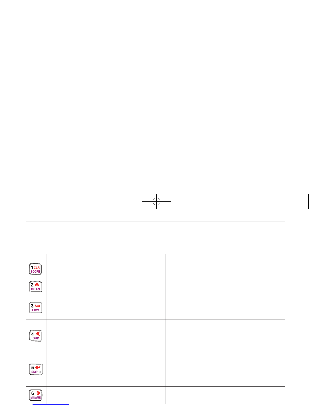
oCALL/RX➝CS KEY [CALL]/[RX➝CS](CALL)
➥Push to select the call channel/TV channel/weather
channel. (p. 16)
➥During DV mode operation, push and hold for 1 sec. to
set the received call signs (station and repeaters) for
operation. (p. 47)
➥Enters or sends the DTMF code “C.” (pgs. 103, 104)
!0MEMORY/SELECT MEMORY WRITE KEY [MR]/[S.
MW](MR)
➥Push to select memory mode. (p. 15)
➥During memory mode operation, push to toggle be-
tween memory and memory bank mode. (p. 68)
➥Push and hold for 1 sec. to enter select memory write
mode. (p. 64)
➥Enters or sends the DTMF code “B.” (pgs. 103, 104)
!1VFO/MHz KEY [VFO]/[MHz](VFO)
➥Push to toggle select VFO mode. (p. 15)
➥During VFO mode operation, push and hold for 1 sec.
to select and toggle 1 MHz and 10 MHz tuning steps
(p. 18)
➥Enters or sends the DTMF code “A.” (pgs. 103, 104)
!2MENU/LOCK KEY [MENU/LOCK]
➥Push to toggle menu screen indication ON and OFF.
(p. 85)
➥Push and hold for 1 sec. to toggle the lock function ON
and OFF. (p. 25)
!3EXTERNAL DC IN JACK [DC IN]
➥Connects the supplied wall charger, BC-167, to charge
the attached battery pack. (p. 10)
➥Connect an external DC power supply through the op-
tional CP-12L, CP-19R or OPC-254L for external DC
operation. (p. 13)
!4DATA JACK [DATA]
Connects a PC through the optional data communication
cable, OPC-1529R, for low-speed data communication or
control the transceiver remotely using the optional RS-91
(OPC-1529R is supplied). (p. 56)
!5VOLUME CONTROL [VOL]
Rotate to adjust the audio output level. (p. 20)
!6CONTROL DIAL [DIAL]
➥Rotate to tune the operating frequency. (p. 18)
➥During memory mode, rotate to select the memory
channel. (pgs. 15, 64)
➥While pushing and holding [BAND], selects the operat-
ing band in VFO mode. (p. 18)
➥
While scanning, changes the scanning direction. (p. 75)
➥While pushing and holding [SQL],sets the squelch
level. (p. 21)
➥While pushing and holding [BAND], selects the pro-
grammed bank in memory mode. (p. 68)
!7EXTERNAL SPEAKER/MICROPHONE JACK [MIC/SP]
Connect an optional speaker-microphone or headset, if
desired.
See page 122 for a list of available options.

Ne
4
2PANEL DESCRIPTION
New2001
DKEYPAD
1
SCOPE
CLR
2
SCAN
KEY Pushed momentarily
3
LOW
A/a
4
DUP
5
SKIP
6
M.NAME
Pushed and held for 1 sec.
• Inputs digit ‘1’ for frequency input, memory channel selection,
etc.
• While pushing [PTT], this key sends the DTMF code “1.”
• Inputs digit ‘2’ for frequency input, memory channel selection,
etc.
• While pushing [PTT], this key sends the DTMF code “2.”
• Inputs digit ‘3’ for frequency input, memory channel selection,
etc.
• While pushing [PTT], this key sends the DTMF code “3.”
• Inputs digit ‘4’ for frequency input, memory channel selection,
etc.
• While pushing [PTT], this key sends the DTMF code “4.”
• Inputs digit ‘5’ for frequency input, memory channel selection,
etc.
• While pushing [PTT], this key sends the DTMF code “5.”
• Inputs digit ‘6’ for frequency input, memory channel selection,
etc.
• While pushing [PTT], this key sends the DTMF code “6.”
• Displays the simple band scope for a single sweep. (p. 23)
• Starts a scan. (p. 75)
• Toggles the transmit output power between high and low (p. 24).
- “LOW” appears when low power is selected.
- While pushing and holding this key, with [DIAL] rotation se-
lects the output power.
• Activates the following duplex functions in order.
- Minus duplex operation— “–DUP” appears.
- Plus duplex operation— “+DUP” appears.
- Simplex operation— no duplex indicator appears.
- While pushing and holding this key, with [DIAL] rotation se-
lects the duplex function.
• Turn the frequency skip function ON and OFF in VFO mode, or
set the memory channel as the following skip channel in mem-
ory mode in order (p. 79).
- Skip channel— “SKIP” appears.
- Frequency skip channel— “PSKIP” appears.
- Non-skip channel— no skip indicator appears.
• Turn the memory name or bank name indication ON and OFF.
(p. 70)

5
2
PANEL DESCRIPTION
New2001
2
9
DTMF
.
M
CS
0
CQ
.
T.SCAN
CD
#
REC
MODE
KEY Pushed momentarily Pushed and held for 1 sec.
• Inputs digit ‘7’ for frequency input, memory channel selection,
etc.
• While pushing [PTT], this key sends the DTMF code “7.”
• Inputs digit ‘8’ for frequency input, memory channel selection,
etc.
• While pushing [PTT], this key sends the DTMF code “8.”
• Inputs digit ‘9’ for frequency input, memory channel selection,
etc.
• While pushing [PTT], this key sends the DTMF code “9.”
• Inputs digit ‘0’ for frequency input, memory channel selection,
etc.
• While pushing [PTT], this key sends the DTMF code “0.”
• Inputs MHz digit for frequency input.
• While pushing [PTT], this key sends the DTMF code “F (#).”
• During DV mode operation, selects the record track for voice
memory. (p. 62)
• While pushing [PTT], this key sends the DTMF code “E (✱).”
• During FM/FM-N mode operation, selects repeater tone, tone
squelch, DTCS squelch and no tone operation in sequence.
(p. 110)
• During DV mode operation, selects digital call sign, digital code
and no tone operation in sequence. (p. 110)
• Selects tuning step selection. (p. 18)
• Select DTMF memory mode. (p. 103)
• During DV mode operation, CALL SIGN setting mode is dis-
played. (p. 51)
• During DV mode operation, set “CQCQCQ” for station’s call
sign for operation.
• During FM/FM-N mode operation, starts tone scan function.
(p. 112)
• During DV mode operation, RX CALL SIGN is displayed. (p. 56)
• Selects the operating mode.
7
TONE
DSQ
8
TS

6
2PANEL DESCRIPTION
New2001 Ne
■Function display
qBATTERY INDICATOR (pgs. 10, 12)
➥“ ” (battery indicators) appear when the Li-Ion bat-
tery pack is attached.
➥“ ” appears when the battery pack must be charged.
➥The indicators show “ ,” “ ” and “ ” in se-
quence while charging the attached battery pack.
wDUPLEX INDICATORS (p. 29)
“+DUP” appears when plus duplex, “–DUP” appears when
minus duplex is selected.
ePRIORITY WATCH INDICATOR (p. 83)
Appears when priority watch is in use.
rTONE INDICATORS
• While operating in FM mode;
➥“TONE” appears while the subaudible tone encoder is
in use. (pgs. 29, 106)
➥“TSQL” appears while the tone squelch function is in
use. (p. 110)
➥“DTCS” appears while the DTCS squelch function is in
use. (p. 110)
➥“S” appears with the “TSQL” or “DTCS” indicator
while the pocket beep function (with CTCSS or DTCS) is
in use. (p. 111)
• While operating in DV mode;
➥“DSQL” appears while the call sign squelch function is
in use. (p. 110)
➥“CSQL” appears while the digital code squelch function
is in use. (p. 110)
• Dualwatch indication
• Single band indication
MemoName
μ
PRIO
PRIO EMR
DSQL
DSQL
DV
B
LOW
ATT
439706
PSKIP
-DUP
-DUP
25
25
000
PS
PS
PRIO
PRIO
25
μ
000
000
88 100
DTCS
PS
PS
PRIO
PRIO
-DUP
-DUP
75
μ
000
000
439706
q
!6 i e o
we r ty
!1
!8!1y !4
!2
!3
!7
q
!4
!5
!6
!7 u
t
!0
!6 w r e o
!8!1!2 !4
!7
i
!3
!0
i
o
!0

7
2
PANEL DESCRIPTION
New2001
2
➥“S” appears with the “DSQL” or “CSQL” indicator
while the pocket beep function (with digital call sign or
digital code squelch) is in use. (p. 111)
tKEY LOCK INDICATOR (pgs. 25, 113)
Appears when the key lock function is activated.
yAUTO POWER OFF INDICATOR (p. 88)
Appears when the auto power OFF function is in use.
uEMR MODE INDICATOR (p. 56)
Appears when the EMR mode operation is selected.
iFREQUENCY READOUT
Displays a variety of information, such as operating fre-
quency, set mode contents, memory names.
• The decimal point blinks during scan.
oSKIP INDICATORS (pgs. 79, 80)
➥“SKIP” appears when the selected memory channel is
set as a skip channel.
➥“P-SKIP” appears when the displayed frequency is set
as a skip frequency.
!0MEMORY CHANNEL NUMBER INDICATOR
➥Shows the selected memory channel number. (pgs. 64,
65)
➥“C” appears when the call channel is selected. (pgs. 16,
65)
➥“WX” appears when the weather channel is selected.
(pgs. 16, 114)
➥“TV” appears when the TV channel is selected.
(pgs. 16, 28)
!1S/RF METER
➥Shows the relative signal strength while receiving sig-
nals.
➥Shows the output power level while transmitting. (p. 24)
!2ATTENUATOR INDICATOR (p. 22)
Appears when the RF attenuator is in use.
!3LOW POWER INDICATOR (p. 24)
➥“LOW” appears when low power is selected.
➥No indicator appears when high power is selected.
!4MEMORY INDICATOR (p. 64)
Appears when memory mode is selected.
!5NAME INDICATOR (p. 70)
During memory mode operation, the programmed mem-
ory or memory bank name is displayed.
!6MAIN BAND INDICATOR (p. 14)
Shows which operating band, “A” or “B,” is selected for the
main band.
!7OPERATING MODE INDICATOR (p. 21)
Shows the selected operating mode.
• DV, FM, FM-N, WFM and AM are available, depending on oper-
ating band.
!8SIMPLE BAND SCOPE INDICATOR (p. 23)
When the simple band scope function is in use, shows
the band conditions.

8
NeNew2001
BATTERY CHARGING
3
■Caution
• RDANGER! Use and charge only specified Icom battery
packs with Icom radios. Only Icom battery packs are tested
and approved for use with Icom radios. Using third-party or
counterfeit battery packs may cause smoke, fire, or cause
the battery to burst.
DBattery caution
• RDANGER! DO NOT hammer or otherwise impact the
battery. Do not use the battery if it has been severely im-
pacted or dropped, or if the battery has been subjected to
heavy pressure. Battery damage may not be visible on the
outside of the case. Even if the surface of the battery does
not show cracks or any other damage, the cells inside the
battery may rupture or catch fire.
• RDANGER! NEVER use or leave battery pack in areas
with temperatures above +60˚C (+140˚F). High tempera-
ture buildup in the battery, such as could occur near fires
or stoves, inside a sun heated car, or in direct sunlight
may cause the battery to rupture or catch fire. Excessive
temperatures may also degrade battery performance or
shorten battery life.
• RDANGER! DO NOT expose the battery to rain, snow,
seawater, or any other liquids. Do not charge or use a wet
battery. If the battery gets wet, be sure to wipe it dry before
using. The battery is not waterproof.
• RDANGER! NEVER incinerate an used battery pack
since internal battery gas may cause it to rupture, or may
cause an explosion.
• RDANGER! NEVER solder the battery terminals, or
NEVER modify the battery pack. This may cause heat gen-
eration, and the battery may burst, emit smoke or catch
fire.
• RDANGER! Use the battery only with the transceiver for
which it is specified. Never use a battery with any other
equipment, or for any purpose that is not specified in this
instruction manual.
• RDANGER! If fluid from inside the battery gets in your
eyes, blindness can result. Rinse your eyes with clean
water, without rubbing them, and see a doctor immediately.
• WARNING! Immediately stop using the battery if it emits
an abnormal odor, heats up, or is discolored or deformed. If
any of these conditions occur, contact your Icom dealer or
distributor.
• WARNING! Immediately wash, using clean water, any part
of the body that comes into contact with fluid from inside
the battery.
Misuse of Lithium-Ion batteries may result in the fol-
lowing hazards: smoke, fire, or the battery may rupture.
Misuse can also cause damage to the battery or degra-
dation of battery performance.

New2001
9
3
BATTERY CHARGING
3
• WARNING! NEVER put the battery in a microwave oven,
high-pressure container, or in an induction heating cooker.
This could cause a fire, overheating, or cause the battery
to rupture.
• CAUTION! Always use the battery within the specified tem-
perature range, –20˚C to +60˚C (–4˚F to +140˚F). Using the
battery out of its specified temperature range will reduce
the battery’s performance and battery life.
• CAUTION! Shorter battery life could occur if the battery
is left fully charged, completely discharged, or in an ex-
cessive temperature environment (above +50˚C; +122˚F)
for an extended period of time. If the battery must be left
unused for a long time, it must be detached from the radio
after discharging. You may use the battery until the battery
indicator shows half-capacity, then keep it safely in a cool
dry place with the temperature between –20˚C to +20˚C (–
4˚F to +68˚F).
DCharging caution
• RDANGER! NEVER charge the battery pack in areas with
extremely high temperatures, such as near fires or stoves,
inside a sun heated car, or in direct sunlight. In such en-
vironments, the safety/protection circuit in the battery will
activate, causing the battery to stop charging.
• WARNING! DO NOT charge or leave the battery in the
battery charger beyond the specified time for charging. If
the battery is not completely charged by the specified time,
stop charging and remove the battery from the battery
charger. Continuing to charge the battery beyond the speci-
fied time limit may cause a fire, overheating, or the battery
may rupture.
• WARNING! NEVER insert the transceiver (battery attached
to the transceiver) into the charger if it is wet or soiled. This
could corrode the battery charger terminals or damage the
charger. The charger is not waterproof.
• CAUTION! DO NOT charge the battery outside of the
specified temperature range: 0˚C to +35˚C (+32˚F to +95˚
F). Icom recommends charging the battery at +20˚C (+68˚
F). The battery may heat up or rupture if charged out of the
specified temperature range. Additionally, battery perform-
ance or battery life may be reduced.

Ne
10
3BATTERY CHARGING
New2001
■Regular charging
Prior to using the transceiver for the first time, the battery
pack must be fully charged for optimum life and operation.
DBattery indicators
The indicators show “ ,” “ ” and “ ” in sequence
while charging, and both indicators disappear when com-
pletely charged.
DCharging note
• Be sure to turn the transceiver power OFF.
Otherwise the battery pack will not be charged completely or takes
longer charging time periods.
• External DC power operation becomes possible when
using an optional CP-12L, CP-19R or OPC-254L. The at-
tached battery pack is also charged simultaneously, except
during transmit. (see p. 11 for more details)
• The external DC power supply voltage must be within 10–
16 V to charge the battery pack and operation when using
an optional OPC-254L.
• BC-167A/D
• CP-12L (Optional)
• OPC-254L (Optional)
to AC outlet
to cigarette lighter
socket (12 V DC)
to 12 V DC
(power supply)
White: +
Black: _
Transceiver
to
[DC IN]
Turn power OFF while
charging the battery
pack.
• Charging time period:
Approx. 6 hours
BP-256 • CP-19R (Optional)

11
3
BATTERY CHARGING
New2001
3
■Rapid charging
The optional BC-177 provides rapid charging of the battery
pack.
• Charging period: approx. 2.5 hours (with BP-256)
DCharging note
• Be sure to turn the transceiver power OFF.
Detach the battery pack from the transceiver then charge
the battery pack by itself, or charge the battery with regu-
lar charging when the transceiver power cannot be turned
OFF.
Otherwise the battery pack will not be charged (charging in-
dicator on the BC-177 blinks orange about 10 sec. after the battery
pack is installed in BC-177).
• The desktop charger, BC-177, can only be charged
BP-256. Other types of rechargeable battery, Ni-Cd or
Ni-MH, cannot be charged.
• If the charging indicator blinks orange, there may be a
problem with the battery pack (or charger). Reinsert the bat-
tery pack or contact your dealer.
• The optional CP-12L and OPC-254L can be used instead
of the supplied AC adapter (BC-123A/E). Connect one of
these to the [DC 13.5V] jack in this case.
Transceiver
(with battery pack)
Turn power OFF. Battery pack
to AC outlet
BC-177 (optional)
Desktop charger
to [AC ADAPTER]
to [DC 13.5V]
CP-12L
OPC-254L
Charging indicator
Charging : Orange
Finished : Green
Charging
terminal
AC adapter
(supplied
with BC-177)

Ne
12
3BATTERY CHARGING
New2001
■Optional battery case
➥Install 2 uLR6 (AA) size
alkaline batteries into the
optional BP-257 BATTERY
CASE.
• Be sure to observe the cor-
rect polarity.
A built-in step-up convertor in the BP-257 increases the
voltage to 5 V DC.
Approx. 100 mW of output power is possible with the
BP-257 operation. Also, no transmit output power selec-
tion is available.
Keep battery contacts clean. It’s a good idea to clean bat-
tery terminals once a week.
DBattery information
The batteries may seem to have low capacity when used in
low temperatures such as –10°C (+14°F) or below. Keep the
battery case or pack warm in this case.
DBattery replacement
When the batteries become exhausted, the function display
may blink or have a lower contrast. In these cases, replace
all batteries with new, same brand, alkaline batteries.
■Battery information
DBattery life
The transceiver operates with the BP-256 as follows.
However, when operating in DV mode, operating time may
be shortened by one-half hour.
• VHF band : Approx. 5 hours
• UHF band : Approx. 4.5 hours
(Tx: Rx: Stand-by=1: 1: 8)
Even when the transceiver power is OFF, a slight current
still flows in the circuits. Remove the battery pack or case
from the transceiver when not using it for a long time. Oth-
erwise, the battery pack or installed batteries will become
exhausted.
DBattery indicator
The battery indicator, “ ,” appears only when the BP-256
is attached to the transceiver.
The battery indicator does not appear when turning power
ON after the charging is completed without disconnecting
the battery charger or external DC power.
Indication Battery condition
The battery has ample capacity.
The battery is nearing exhaustion. Charging is neces-
sary.

13
3
BATTERY CHARGING
New2001
3
■External DC power operation
An optional cigarette lighter cable (CP-12L or CP-19R; for 12 V
cigarette lighter socket) or external DC power cable (OPC-254L)
can be used for external power operation.
DOperating note
• Power supply range is between 10.0–16.0 V DC.
NEVER CONNECT OVER 16 V DC directly into the [DC IN]
jack of the transceiver.
• BE SURE to use CP-12L,CP-19R or OPC-254L when con-
necting a regulated 12 V DC power supply.
Use an external DC-DC converter to connect the trans-
ceiver through optional CP-12L, CP-19R or OPC-254L to a
24 V DC power source.
• The voltage of the external power supply must be within
10–16 V DC when using either CP-12L, CP-19R or OPC-
254L, otherwise, use the battery pack.
• Up to 5 W (approx.) of maximum output power is provided
with the external DC power operation, however, when the
supplied voltage exceeds 14 V, the built-in protection circuit
activates to reduce the transmit output power to 0.5 W (ap-
prox.).
• Disconnect the power cables from the transceiver when
not using it. Otherwise, the vehicle battery will become ex-
hausted.
• The power save function is deactivated automatically dur-
ing external DC power operation.
Transceiver
• CP-12L (Optional)
• CP-19R (Optional)
• OPC-254L (Optional)
to cigarette lighter
socket (12 V DC)
to 12 V DC
(power supply)
White: +
Black: _
to
[DC IN]

14
NeNew2001
FREQUENCY AND CHANNEL SETTING
4
■Main band selection
The IC-92A/92AD has two independent operating bands; A
band (VFO A) and B band (VFO B). A band (VFO A) can oper-
ate 0.495 MHz to 999.990 MHz*, and B band (VFO B) can
operate 118 MHz to 174 MHz and 350 MHz to 470 MHz.
*Some frequency ranges are blocked for the USA version by regula-
tion.
NOTE: When in dualwatch mode, transmission is avail-
able from the MAIN band only.
DHow to change the main band
➥Push [MAIN/DUAL] to toggle between A and B band.
➥Push and hold [MAIN/DUAL] for 1 sec. to turn the dual-
watch operation ON and OFF.
• While in dualwatch operation, the display indicates A band in
the upper half and B band in the lower half.
➥During dualwatch operation, push [MAIN/DUAL] to select
A band or B band as the main operating band alternately.
DTCS
DTCS
W
PS
EMEM
W
PS
FMFM
PRIOPRIO
PRIOPRIO
+DUP+DUP
+DUP+DUP
FM
146010
440000000
25
50
μ
000000
μ
000000
DTCS
DTCS
W
PS
EMEM
W
PS
FMFM
PRIOPRIO
PRIOPRIO
+DUP+DUP
+DUP+DUP
FM
146010
440000
25
50
μ
000000
μ
000000
A
MemoNameMemoName
μ
PRIO WX EMR
DTCS
FM
LOW
ATT
146010
PSKIPSKIP
+DUP
2525
000000
MemoName
μ
PRIOPRIO WXWX EMREMR
DTCSDTCS
FMFM
B
LOW
ATT
440000
PSKIPSKIP
+DUP+DUP
2525
000
Push Push
• Selecting A band • Selecting upper side as main band
• Selecting lower side as main band
• Selecting B band
Push
DTCS
DTCS
W
PS
EM
W
PS
FM
PRIO
PRIO
+DUP
+DUP
FM
146 010
440 000
25
50
μ
000
μ
000
DTCS
DTCS
W
PS
EM
W
PS
FM
PRIO
PRIO
+DUP
+DUP
FM
146 010
440 000
25
50
μ
000
μ
000
A
MemoName
μ
PRIO WX EMR
DTCS
FM
LOW
ATT
146010
P SKIP
+DUP
25
000
MemoName
μ
PRIO WX EMR
DTCS
FM
B
LOW
ATT
440000
P SKIP
+DUP
25
000
Single band operation Dualwatch operation
for 1 sec.
This manual suits for next models
1
Table of contents
Other Icom Transceiver manuals