Icom IC-M402 User manual

iM402
VHF MARINE TRANSCEIVER
This device complies with Part 15 of the FCC rules. Operation is sub-
ject to the following two conditions: (1) This device may not cause
harmful interference, and (2) this device must accept any interference
received, including interference that may cause undesired operation.
IC-M402
INSTRUCTION MANUAL
iM402S
VHF MARINE TRANSCEIVER
(REMOTE-CONTROL MIC COMPATIBLE)
00_IC-M402_S.qxd 02.2.21 0:06 PM Page a (1,1)

i
FOREWORD
Thank you for purchasing this Icom product. The
IC-M402/M402S VHF MARINE TRANSCEIVERs are de-
signed and built with Icom’s superior technology and crafts-
manship. With proper care, this product should provide you
with years of trouble-free operation.
We want to take a couple of moments of your time to thank
you for making your IC-M402/M402S your radio of choice,
and hope you agree with Icom’s philosophy of “technology
first.” Many hours of research and development went into the
design of your IC-M402/M402S.
ïï
FEATURES
❍large 2-digit Ch with scrolling channel names
❍Easy to hear speaker
❍Built-in DSC capability that meets RTCM SC101
❍Rugged waterproof construction
❍Optional COMMANDMICTM (IC-M402 only)
WARNING.
WARNING
STICKER
NOTE
A WARNING STICKER is supplied with the transceiver.
To comply with FCC regulations, this sticker must be affixed in
such a location as to be readily seen from the operating con-
trols of the radio like as follows. Make sure the chosen loca-
tion is clean and dry before applying the sticker. (p. 22)
EXAMPLE
00_IC-M402_S.qxd 02.2.21 0:06 PM Page c (1,1)

ii
IMPORTANT
READ ALL INSTRUCTIONS carefully and completely
before using the transceiver.
SAVE THIS INSTRUCTION MANUAL—This in-
struction manual contains important operating instructions for
the IC-M402/M402S.
IN CASE OF EMERGENCY
If your vessel requires assistance, contact other vessels and
the Coast Guard by sending a distress call on Ch 16.
Or, transmit your distress call using digital selective calling on
Ch 70.
USING CHANNEL 16
DISTRESS CALL PROCEDURE
1. “MAYDAY MAYDAY MAYDAY.”
2. “THIS IS ...............”(name of vessel)
3. Your call sign or other indication of the vessel (AND 9-
digit DSC ID if you have one).
4. “LOCATED AT ...............”(your position)
5. The nature of the distress and assistance required.
6. Any other information which might facilitate the rescue.
USING DIGITAL SELECTIVE CALLING (Ch 70)
DISTRESS CALL PROCEDURE
1. While lifting up the switch cover, push and hold
[DISTRESS] for 5 sec. until you hear 5 short beeps
change to one long beep.
2. Wait for an acknowledgment from a coast station.
•Channel 16 is automatically selected.
3. Push and hold [PTT], then transmit the appropriate
information as at left.
WORD
R
WARNING
CAUTION
NOTE
DEFINITION
Personal injury, fire hazard or electric
shock may occur.
If disregarded, inconvenience only. No risk
of personal injury, fire or electric shock.
Equipment damage may occur.
EXPLICIT DEFINITIONS
00_IC-M402_S.qxd 02.2.21 0:06 PM Page d (1,1)

iii
RWARNING! NEVER connect the transceiver to an AC
outlet. This may pose a fire hazard or result in an electric
shock.
CAUTION: Changes or modifications to this device, not ex-
pressly approved by Icom Inc., could void your authority to
operate this device under FCC regulations.
NEVER connect the transceiver to a power source of more
than 16 V DC or use reverse polarity. This will ruin the trans-
ceiver.
NEVER cut the DC power cable between the DC plug and
fuse holder. If an incorrect connection is made after cutting,
the transceiver may be damaged.
NEVER place the transceiver where normal operation of the
vehicle may be hindered or where it could cause bodily injury.
KEEP the transceiver at least 3.3 ft (1 m) away from the
ship’s navigation compass.
DO NOT use or place the transceiver in areas with temper-
atures below –4°F (–20°C) or above +140°F (+60°C) or, in
areas subject to direct sunlight, such as the dashboard.
AVOID the use of chemical agents such as benzine or al-
cohol when cleaning, as they may damage the transceiver
surfaces.
BE CAREFUL! The transceiver rear panel will become
hot when operating continuously for long periods.
Place the transceiver in a secure place to avoid inadvertent
use by children.
BE CAREFUL! The transceiver and optional HM-127*
employ waterproof construction, which corresponds to JIS
waterproof specification, grade 7 (1 m/30 min.). However,
once the transceiver or microphone has been dropped, water-
proofing cannot be guaranteed due to the fact that the case
may be cracked, or the waterproof seal damaged, etc.
*IC-M402 only.
CAUTIONS
Icom, Icom Inc. and the logo are registered trademarks of
Icom Incorporated (Japan) in the United states, the United
Kingdom, Germany, France, Spain, Russia and/or other coun-
tries.
00_IC-M402_S.qxd 02.2.21 0:06 PM Page e (1,1)

iv
Icom requires the radio operator to meet the
FCC Requirements for Radio Frequency Expo-
sure.An omnidirectional antenna with gain not
greater than 9 dBi must be mounted a minimum
of 5 meters (measured from the lowest point of
the antenna) vertically above the main deck and all possible
personnel. This is the minimum safe separation distance esti-
mated to meet all RF exposure compliance requirements.
This 5 meter distance is based on the FCC Safe Maximum
Permissible Exposure (MPE) distance of 3 meters added to
the height of an adult (2 meters) and is appropriate for all ves-
sels.
For watercraft without suitable structures, the antenna must
be mounted so as to maintain a minimum of 1 meter vertically
between the antenna, (measured from the lowest point of the
antenna), to the heads of all persons AND all persons must
stay outside of the 3 meter MPE radius.
Do not transmit with radio and antenna when persons are
within the MPE radius of the antenna, unless such persons
(such as driver or radio operator) are shielded from antenna
field by a grounded metallic barrier. The MPE Radius is the
minimum distance from the antenna axis that person should
maintain in order to avoid RF exposure higher than the allow-
able MPE level set by FCC.
FAILURE TO OBSERVE THESE LIMITS MAY ALLOW
THOSE WITHIN THE MPE RADIUS TO EXPERIENCE RF
RADIATION ABSORPTION WHICH EXCEEDS THE FCC
MAXIMUM PERMISSIBLE EXPOSURE (MPE) LIMIT.
IT IS THE RESPONSIBILITY OF THE RADIO OPERATOR
TO ENSURE THAT THE MAXIMUM PERMISSIBLE EXPO-
SURE LIMITS ARE OBSERVED AT ALL TIMES DURING
RADIO TRANSMISSION. THE RADIO OPERATOR IS TO
ENSURE THAT NO BYSTANDERS COME WITHIN THE
RADIUS OF THE MAXIMUM PERMISSIBLE EXPOSURE
LIMITS.
Determining MPE Radius
THE MAXIMUM PERMISSIBLE EXPOSURE (MPE) RA-
DIUS HAS BEEN ESTIMATED TO BE A RADIUS OF
ABOUT 3M PER OET BULLETIN 65 OF THE FCC.
THIS ESTIMATE IS MADE ASSUMING THE MAXIMUM
POWER OF THE RADIO AND ANTENNAS WITH A MAXI-
MUM GAIN OF 9dBi ARE USED FOR A SHIP MOUNTED
SYSTEM.
RADIO OPERATOR WARNING
WARNING
00_IC-M402_S.qxd 02.2.21 0:06 PM Page f (1,1)

v
TABLE OF CONTENTS
FOREWORD ...............................................i
NOTE...........................................................i
IMPORTANT ...............................................ii
EXPLICIT DEFINITIONS ............................ii
IN CASE OF EMERGENCY .......................ii
CAUTIONS.................................................iii
RADIO OPERATOR WARNING.................iv
TABLE OF CONTENTS ..............................v
1 OPERATING RULES .......................... 1
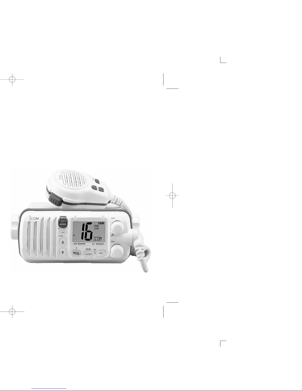
2 PANEL DESCRIPTION .................. 2 – 4
■ Panel description ............................. 2
■ Function display ............................... 3
■ Microphone ...................................... 4
3 BASIC OPERATION ....................... 5 – 7
■ Channel selection ............................. 5
■ Microphone lock function .................. 6
■ Receiving and transmitting ............... 6
■ Call channel programming................ 7
■
Channel names
.................................. 7
4 DUALWATCH/TRI-WATCH .................. 8
■ Description ....................................... 8
■ Operation .......................................... 8
5 SCAN OPERATIONS .................... 9 – 10
■ Setting tag channels ......................... 9
■ Starting a scan.................................. 9
■ Scan types ..................................... 10
6 DSC OPERATION ....................... 11 – 18
■ MMSI code programming................ 11
■ MMSI code check ........................... 11
■ Position indication ........................... 11
■ Distress call .................................... 12
■ Transmitting DSC calls ................... 13
■ DSC individual ID............................ 16
■ Receiving DSC calls ....................... 16
7 INTERCOM OPERATION
(IC-M402 only) ................................... 19
■ Intercom operation.......................... 19
8 SET MODE .................................. 20 – 21
■ Set mode programming .................. 20
■ Set mode items............................... 20
9 CONNECTIONS AND
MAINTENANCE ........................... 22-25
■ Supplied accessories...................... 22
■ Antenna .......................................... 22
■ Fuse replacement ........................... 22
■ Cleaning.......................................... 22
■ Connections ................................... 23
■ Mounting the transceiver ................ 24
■ MB-69 mounting bracket (Option)... 25
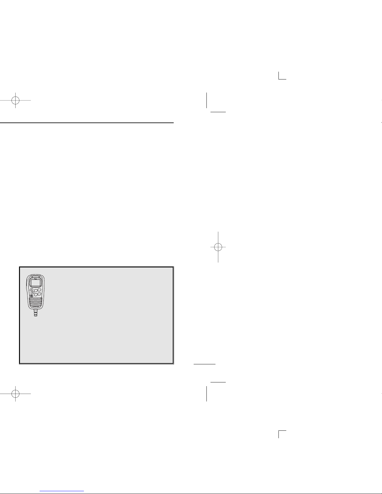
10 HM-127 REMOTE-CONTROL
MICROPHONE (IC-M402 only)....... 26-37
■ Panel description .............................26
■ Function display...............................28
■ Receiving and transmitting ..............29
■ Lock functions..................................30
■ Channel selection ............................31
■ Display backlighting .........................32
■ Monitor function ...............................32
■ Call channel programming...............32
■ Starting a scan.................................33
■ Setting tag channels ........................33
■ Dualwatch/Tri-watch operation ........33
■ Set mode programming ...................34
■ Intercom operation...........................34
■ Channel names................................35
■ HM-127 supplied accessories..........35
■ Installation ..................................36-37
11 TROUBLESHOOTING ....................... 38
12 CHANNEL LIST ................................. 39
13 SPECIFICATIONS ........................ 40-41
■ Specifications.................................. 40
■ Dimensions ..................................... 41
14 MB-69/HM-127 TEMPLATE............... 42
15 OPTIONS ........................................... 44
00_IC-M402_S.qxd 02.2.21 0:06 PM Page g (1,1)

1OPERATING RULES
■Channel selection
ïïPRIORITIES
•Read all rules and regulations pertaining to priorities and keep an
up-to-date copy handy. Safety and distress calls take priority over
all others.
•You should monitor Ch 16 when you are not operating on another
channel.
•False or fraudulent distress signals are prohibited and punishable
by law.
ïïPRIVACY
•Information overheard but not intended for you cannot law-fully be
used in any way.
•Indecent or profane language is prohibited.
ïïRADIO LICENSES
(1) SHIP STATION LICENSE
In some countries, you must have a current radio station li-
cense before using the transceiver.
Inquire through your dealer or the appropriate government
agency for a Ship-Radiotelephone license application. This
government-issued license states the call sign which is your
craft’s identification for radio purposes.
(2) OPERATOR’S LICENSE
A Restricted Radiotelephone Operator Permit is the license
most often held by small vessel radio operators when a radio
is not required for safety purposes.
The Restricted Radiotelephone Operator Permit must be
posted or kept with the operator.
However, non-licensed individuals may talk over a transceiver
if a licensed operator starts, supervises, ends the call and
makes the necessary log entries.
Keep a copy of the current government rules and regulations
handy.
Radio license for boaters (U.S.A. only)
The Telecommunications Act of 1996 permits recreational
boaters to have and use a VHF marine radio, EPIRB, and
marine radar without having an FCC ship station license.
Boaters travelling on international voyages, having an HF
single sideband radiotelephone or marine satellite terminal,
or required to carry a marine radio under any other regula-
tion must still carry an FCC ship station license. For further
information, see the FCC Ship Radio Stations Fact Sheet.
1
00_IC-M402_S.qxd 02.2.21 0:06 PM Page 1 (1,1)

2
2
PANEL DESCRIPTION
qDISTRESS SWITCH [DISTRESS]
Transmits distress call when pushed for 5 sec. (p. 12)
wPOWER / VOLUME CONTROL [VOL]
Turns power ON and OFF and adjusts the audio level. (p. 6)
eSQUELCH CONTROL [SQL]
Sets the squelch threshold level. (p. 6)
rTRANSMIT POWER SWITCH [H/L]
➥Toggles high and low power when pushed. (p. 6)
•Some channels are set to low power only.
➥While pushing this switch, other switches perform sec-
ondary functions.
tCHANNEL SWITCH [CH/WX•DUAL]
➥Selects and toggles the regular channels and weather
channel when pushed momentarily. (p. 5)
➥While push and hold [H/L] push [CH/WX•DUAL] to se-
lects one of 3 regular channels in sequence. (p. 5)
•International, U.S.A. and Canadian channels are available for
regular channels.
➥Starts dualwatch or tri-watch when pushed for 1 sec.
(p. 8)
➥Stops dualwatch or tri-watch when either is activated.
yCHANNEL 16/CALL CHANNEL SWITCH [16•9]
➥Selects Ch 16 when pushed. (p. 5)
➥Selects call channel when pushed for 1 sec. (p. 5)
•“CALL”appears when call channel is selected.
➥Push for 3 sec. to enter call channel programming con-
dition when call channel is selected. (p. 7)
➥While push and hold [H/L] push [16•9] to enter memory
name programming condition. (p. 7)
➥While turning power ON push [16•9] to enter set mode.
(p. 20)
uCHANNEL UP / DOWN SWITCHES [YY/ZZ•SCAN]
➥Push to select the operating channels, set mode con-
tents, etc. (p. 6)
➥While push and hold [H/L] push [Y]/[Z] to adjust the
brightness of the LCD and switch backlight.
➥Push for 3 sec. to enter call channel programming con-
dition when call channel is selected. (p. 7)
➥Push [Y] or [Z] for 1sec. to start/stop scanning. (p. 10)
➥Push [Y] and [Z] for 1sec. to toggle the tag setting for
the displayed channel. (p. 10)
iDSC/INTERCOM SWITCH [DSC/IC] ([DSC] for IC-M402S)
➥Selects the DSC menu when pushed. (p. 11)
➥While push and hold [H/L] push [DSC] for 1 sec. to show
current position and time. (p. 11)
➥Push [DSC] for 1 sec. to enter intercom mode.
(IC-M402 only, p. 19)
Speaker Function display wq
uertyi IC-M402
■Panel description
00_IC-M402_S.qxd 02.2.21 0:06 PM Page 2 (1,1)

■Function display
qTRANSMIT INDICATOR (p. 6)
“TX”appears while transmitting.
wBUSY INDICATOR (p. 6)
“BUSY”appears when receiving a signal or when the
squelch opens.
eTAG CHANNEL INDICATOR (p. 9)
Appears when a tag channel is selected.
rCALL CHANNEL INDICATOR
“CALL”appears when the call channel is selected. (p. 5)
tLOW POWER INDICATOR (p. 6)
“LOW”appears when low power is selected.
yDUPLEX INDICATOR (p. 5)
“”Appears when a duplex channel is selected.
uWEATHER CHANNEL INDICATOR (p. 6)
➥“WX”appears when a weather channel is selected.
➥“ALT”appears when the weather alert function is in use;
flashes when an alert tone is received.
iGPS INDICATOR
➥“GPS”appears while valid position data is received.
➥“GPS”blinks when invalid position data is received.
➥“GPS”disappears when no GPS receiver is connected.
oDSC INDICATOR
➥Indicates the DSC status.
!0 CHANNEL NAME INDICATOR
➥Channel comment appears if programmed. (p. 7).
➥“LOW BATTERY”scrolls when the battery voltage drops
to approx. 10 V DC or below.
➥“DW”appears during dualwatch; “TW”appears during
tri-watch. (p. 8)
!1 CHANNEL NUMBER READOUT
➥Indicates the selected operating channel number. “A”
appears when a simplex channel is selected. (p. 5)
➥In set mode, indicates the selected condition. (p. 20)
!2 CHANNEL NUMBER READOUT
Indicates whether a U.S.A. (USA), International (INT), or
Canadian (CANADA) channel is in use.
wq
!1
!2
e
r
t
y
u
i
o
!0
PANEL DESCRIPTION
3
2
00_IC-M402_S.qxd 02.2.21 0:07 PM Page 3 (1,1)

4
2
PANEL DESCRIPTION
■Microphone
qPTT SWITCH [PTT]
Push and hold to transmit; release to receive. (p. 6)
wCHANNEL UP/DOWN SWITCHES [YY]/[ZZ]
Push either switch to change the operating channel, set
mode contents, etc. (p. 6)
eCHANNEL 16/CALL CHANNEL SWITCH [16/9]
➥Same function as the [16•9] switch on the front panel.
(p. 2)
•Selects Ch 16 when pushed. (p. 5)
•Selects call channel when pushed for 1 sec. (p. 5)
•“CALL”appears when call channel is selected.
•Push for 3 sec. to enter call channel programming mode
when call channel is selected. (p. 7)
•While push and hold [H/L] on the front panel push [16/9]
to enter memory channel name programming condition.
(p. 7)
•While push and hold [16/9] on the supplied microphone,
turn power ON to toggle the microphone lock function ON
and OFF. (p. 6)
Microphone
w
q
e
NOTE:
The optional HM-127
REMOTE CONTROL
MICROPHONE
and OPC-999
MICROPHONE
EXTENSION CABLE
can be connected to IC-M402
only.
➥p. 19 Intercom operation
➥p. 26-37 HM-127 REMOTE-CONTROL
MICROPHONE )
IC-M402S has no external microphone
speaker jack for connecting HM-127 and
OPC-999.
00_IC-M402_S.qxd 02.2.21 0:07 PM Page 4 (1,1)

5
3BASIC OPERATION
■Channel selection
ïïChannel 16
Ch 16 is the distress and safety channel. It is used for estab-
lishing initial contact with another station and for emergency
communications. Channel 16 is monitored during both dual-
watch and tri-watch. While standing by, you must monitor Ch 16.
➥Push [16 ] momentarily to select Ch 16.
➥Push [CH/WX] to return to the
condition before selecting Ch 16,
or push [Y]/[Z] to select an op-
erating channel.
ïïChannel 9 (Call channel)
Each regular channel group has a separate leisure-use call
channel. The call channel is monitored during tri-watch. The
call channels can be programmed (p. 7) and are used to store
your most often used channels in each channel group for
quick recall.
➥Push [16] for 1 sec. to select the call channel of the se-
lected channel group.
•“CALLING”and call channel number appear.
•Each channel group may have an independent call channel.
➥Push [CH/WX] to return to the
condition before selecting call
channel, or push [Y]/[Z] to se-
lect an operating channel.
ïïU.S.A.,Canadian and international channels
There are 57 U.S.A., 61 Canadian and 57 international chan-
nels.These channel groups may be specified for the operating
area.
qPush [CH/WX] to select a regular channel.
•If a weather channel appears, push [CH/WX] again.
wPush [CH/WX] while pushing [H/L] to change the channel
group, if necessary.
•U.S.A., International (INT) and Canadian channels can be se-
lected in sequence.
eRotate the channel selector to select a channel.
•“D”appears for duplex channels.
•“A”appears for simplex channels.
Push
Push
Push +
U.S.A. channels
International channelsCanadian channels
00_IC-M402_S.qxd 02.2.21 0:07 PM Page 5 (1,1)

3
BASIC OPERATION
6
ïïWeather channels
There are 10 weather channels. Used for monitoring weather
channels from the NOAA (National Oceanographic and At-
mospheric Administration) broadcasts.
The transceiver can detect a weather alert tone on the se-
lected weather channel while receiving the channel, during
standby on a regular channel or while scanning. (p. 20)
qPush [CH/WX] once or twice
to select a weather channel.
•“WX”appears when a weather
channel is selected. “WX ALT”
appears when the weather alert
function is in use. (p. 20)
wPush [Y]/[Z] to select a chan-
nel.
•Channels are memorized sepa-
rately for each channel group.
■Microphone lock function
The microphone lock function electrically locks the [Y]/[Z] and
[16/9] switches on the supplied microphone. This prevents ac-
cidental channel changes and accidental function access.
➥While pushing [16/9] on the supplied microphone, turn
power ON to toggle the lock function ON and OFF.
■Receiving and transmitting
CAUTION: Transmitting without an antenna may dam-
age the transceiver.
qTurn [VOL] right to turn power ON.
wSet the audio and squelch levels.
➥Rotate [SQL] fully counterclockwise in advance.
➥Rotate [VOL] to adjust the audio output level.
➥Rotate [SQL] clockwise until the noise disappears.
ePush [Y]/[Z] to select the desired channel. (p. 5)
•When receiving a signal, “BUSY”appears and audio is emitted
from the speaker.
rPush [H/L] to select the output power if necessary.
•“LOW”appears when low power is selected.
•Choose high power for stronger signal propagation.
•Some channels are for low power only.
tPush and hold [PTT] to transmit, then speak into the mi-
crophone.
•“TX”appears.
•Channel 70 cannot be used for transmission (for DSC use).
Simplex channels, 3, 21, 23, 61, 64, 81, 82 and 83 CAN-
NOT be lawfully used by the general public in U.S.A. wa-
ters.
yRelease [PTT] to receive.
IMPORTANT: To maximize the readability of your trans-
mitted signal, pause a few sec. after pushing [PTT], hold
the microphone 1 to 2 inches (2.5 to 5 cm) from your
mouth and speak at a normal voice level.
Push
once
or
twice
When weather alert is OFF.
When weather alert is ON.
00_IC-M402_S.qxd 02.2.21 0:07 PM Page 6 (1,1)

■Call channel programming
The call channel is used to select Ch 9, however, you can
program your most often-used channels in each channel
group for quick recall.
qWhile pushing [H/L], push [CH/WX] one or more times to
select the desired channel group (U.S.A., International,
Canada) to be programmed.
wPush [16] for 1 sec. to select the call channel of the se-
lected channel group.
•“CALL”and call channel number appear.
ePush [16] again for 3 sec. (until
long beep changes to 2 short
beeps) to enter call channel pro-
gramming mode.
•Channel number starts flashing.
rPush [Y]/[Z] to select the de-
sired channel.
tPush [16] to program the dis-
played channel as the call chan-
nel.
•Push [CH/WX] to cancel.
•The channel number stops flash-
ing.
■Channel names
Memory channels can be tagged with alphanumeric names
of up to 10 characters each.
Capital letters, small letters, numerals, some symbols (! " # $
% & ' ( ) ✱+ ,–. ⁄) and spaces can be used.
qSelect the desired memory channel.
•Cancel dualwatch, tri-watch or scan in advance.
wWhile pushing [H/L], push [16] to edit memory channel
name.
•A cursor appears and blinks.
eSelect the desired character by pushing [Y]/[Z].
•Push [CH/WX] or [H/L] for cursor movement.
rPush [16] to input and set the name.
•Push [H/L] to cancel.
•The cursor disappears.
tRepeat steps qto rto program other memory channel
names, if desired.
3BASIC OPERATION
7
00_IC-M402_S.qxd 02.2.21 0:07 PM Page 7 (1,1)

[Example]:
Operating dualwatch on INT
Ch 25
Operating tri-watch on INT
Ch 25
3
BASIC OPERATION
8
■Description
Dualwatch monitors Ch 16 while you are receiving an-other
channel; tri-watch monitors Ch 16 and the call channel while
receiving another channel.
DUALWATCH/TRI-WATCH SIMULATION
•If a signal is received on Channel 16, dualwatch/tri-watch pauses
on Ch 16 until the signal disappears.
•If a signal is received on the call channel during tri-watch, tri-watch
becomes dualwatch until the signal disappears.
•To transmit on the selected channel during dualwatch/tri-watch, push
and hold [PTT].
■Operation
qSelect the desired operating channel.
wSelect dualwatch or tri-watch in set mode. (p. 20)
ePush [CH/WX] for 1 sec. to start dualwatch or tri-watch.
•“DW”appears during dualwatch; “TW”appears during tri-watch.
•Beep tone sounds when a signal is received on Channel 16.
rTo cancel dualwatch/tri-watch, push [CH/WX] again.
Dualwatch Tri-watch
Call channel
Dual-watch
starts.
Signal received
on channel 16
takes priority.
Dual-watch
resumes after
the signal
disappears.
Tri-watch
starts.
Signal is
received on
call channel.
Signal received
on channel 16
takes priority.
Tri-watch
resumes after
the signal
disappears.
00_IC-M402_S.qxd 02.2.21 0:07 PM Page 8 (1,1)

9
5SCAN OPERATIONS
■Setting tag channels
For more efficient scanning, add desired channels as tag
channels or clear tag channels for unwanted channels. Chan-
nels set as non-tag channels will be skipped during scanning.
Tag channels can be assigned to each channel group
(U.S.A., International, Canada) independently.
qWhile pushing [H/L], push [CH/WX] one or more times to
select the desired channel group, if desired.
wSelect the desired channel to set as a tag channel.
ePush [Y] and [Z] simultaneously for 1 sec. to set the dis-
played channel as a tag channel.
•“TAG”appears in the function display.
rTo cancel the tag channel setting, repeat e.
•“TAG”disappears.
•Clearing all tag channels in the selected channel group
➥While pushing [Y] and [Z], Turn power ON to clear all tag
channels in the channel group.
■Starting a scan
Set scan type (priority or normal scan) and scan resume timer
in advance using set mode. (p. 20)
qSet tag channels as described at left.
wMake sure the squelch is closed to start a scan.
eWhile pushing [H/L], push [CH/WX] one or more times to
select the desired channel group, if desired.
rPush [Y] or [Z] for 1 sec. to start priority or normal scan.
•“Pri scan 16”or “Normal scan”appears in the function display.
•When a signal is detected, scan pauses until the signal disap-
pears or resumes after pausing 5 sec. according to set mode set-
ting. (Channel 16 is still monitored during priority scan.)
•While in the scanning, use [Y] and [Z] key to check tag channels,
change the scanning direction or resume the scan manually.
•“16”flashes and a beep tone sounds when a signal is received
on Channel 16 during priority scan.
•Push [Y] and [Z] for 1 sec. to set the paused channel as a tag
channel.
tTo stop the scan, push [Y] or [Z].
Scan starts. When a signal is received
[Example]: Starting a priority scan.
00_IC-M402_S.qxd 02.2.21 0:07 PM Page 9 (1,1)

5
SCAN OPERATION
10
■Scan types
Scanning is an efficient way to locate signals quickly over a
wide frequency range. The transceiver has priority scan and
normal scan.
When the weather alert function is in use, the selected
weather channel is checked while scanning. (p. 20)
Set the tag channels (scanned channel) before scanning.
Clear the tag channels which inconveniently stop scanning,
such as digital communication use.
Choose priority or normal scan in set mode. (p. 20)
NORMAL SCAN
Normal scan, like priority scan, searches through all tag
channels in sequence. However, unlike priority scan, Ch 16
is not checked unless Ch 16 is set as a tag channel.
CH 01 CH 02
CH 06
CH 05 CH 04
CH 03
PRIORITY SCAN
Priority scan searches through all tag channels in se-
quence while monitoring Ch 16. When a signal is detected
on Ch 16, scan pauses until the signal disappears; when a
signal is detected on a channel other than Ch 16, scan be-
comes dualwatch until the signal disappears.
CH 06
CH 01
CH 16
CH 02
CH 05 CH 04
CH 03
00_IC-M402_S.qxd 02.2.21 0:07 PM Page 10 (1,1)

11
6DSC OPERATION
■MMSI code programming
The 9-digit MMSI (DSC self ID) code can be programmed at
power ON.
This function is not available when the MMSI code has
been programmed by the dealer. This code programming
can be performed only 2 times.
qTurn power OFF.
wWhile pushing [DSC], turn power ON to enter MMSI code
programming condition.
eAfter the display appears, release [DSC].
rSelect the desired number by pushing [Y]/[Z] .
tPush [H/L] to advance the cursor.
•Push [CH/WX] to move the cursor backward.
yRepeat steps rand tto input 9 digit code.
uPush [DSC] to input and set the code.
•The previously selected channel ap-
pears.
■MMSI code check
The 9-digit MMSI (DSC self ID) code can be checked.
qPush [DSC] to select the DSC menu.
wPush [Y]/[Z] to select “MMSI”and
push [DSC].
eCheck the 9-digit MMSI (DSC self ID)
code.
rPush [DSC] to exit the condition.
■Position indication
When a GPS receiver (NMEA0183 ver. 2.0) is connected, the
transceiver can display the current position and time.
➥While pushing [H/L], push [DSC] for 1 sec. to display the
current position.
•“Latitude and longitude are displayed alternately.
00_IC-M402_S.qxd 02.2.21 0:07 PM Page 11 (1,1)

12
6
DSC OPERATION
■Distress call
A distress call should be transmitted if, in the opinion of the
Master, the ship or a person is in distress and requires imme-
diate assistance.
•All keys, switches and controllers on the transceiver are functional.
NEVER USE THE DISTRESS CALL WHEN YOUR
SHIP IS NOT IN AN EMERGENCY. A DISTRESS
CALL CAN BE USED ONLY WHEN IMMEDIATE
HELP IS NEEDED.
qConfirm that a distress call is not being received.
wWhile lifting up the switch cover, push
the [DISTRESS] switch for 5 sec. to
transmit the distress call.
•An emergency channel (Ch 70) is auto-
matically selected and the distress call is
transmitted.
eAfter transmitting the call, the trans-
ceiver waits for an acknowledgment
call on Ch70.
•The distress call is automatically trans-
mitted every 3.5 to 4.5
•”DSC RPEAT”scrolls.
rWhen receiving the acknowledgment,
reply to the connected station via the
microphone.
•”RCV Distress ACK”scrolls.
➥Distress alert contains (default);
•Kinds of distress : Undesignated distress
•Position data : Latest GPS position data held for 23.5 hrs. or
until the power is turned OFF.
➥The distress call is repeated every 3.5–4.5 min., until re-
ceiving an ‘acknowledgement.’
➥Push [DISTRESS] to transmit a renewed distress call, if
desired.
➥Push [16] to cancel the ‘Call repeat’mode.
00_IC-M402_S.qxd 02.2.21 0:07 PM Page 12 (1,1)

13
6DSC OPERATION
■Transmitting DSC calls
ïïTransmitting individual call
The individual call function allows you to transmit a DSC sig-
nal to a specific party only.
qSelect a desired channel other than
Ch 70.
wPush [DSC] to select the DSC menu.
ePush [Y]/[Z] to select “individual”and
push [DSC].
rPush [Y]/[Z] to select the desired
pre-programmed individual address.
•TheID code for the individual call can be
set in advance. (p. 16)
tPush [DSC] to enter pre-programmed individual address.
•”OK”appears.
yPush [DSC] to transmit the individual call.
•Chl 70 is selected and the individual call is transmitted to the se-
lected station.
•If Ch 70 is busy, the transceiver stands by until the channel be-
comes clear.
•Routine category only is available.
uStandby on Ch 70 until an acknowl-
edgement is received.
•”WAITING ACK”scrolls.
iWhen the acknowledgement is re-
ceived, the display changes to the
previously selected user channel with beeps.
oPush and hold [PTT] to communicate your message to the
responding party.
Push [DSC] to transmit DSC call. When Ch 70 is busy.
00_IC-M402_S.qxd 02.2.21 0:07 PM Page 13 (1,1)

14
6
DSC OPERATION
ïïTransmitting individual acknowledgement
Transmit an acknowledgement (‘able to comply’or ‘unable to
comply’) when an individual call for you is received.
q“RCV Individual”scrolls.
wPush [Y] or [Z] to select the acknowledgement “ABLE”or
“UNABLE”.
ePush [DSC] to enter selected individ-
ual call acknowledgement, “OK”ap-
pears.
rPush [DSC] to transmit individual call
acknowledgement.
tIf you select “Able”,the channel spec-
ified by the calling station is automat-
ically selected.
ïïTransmitting all ships call
Large ships use Ch 70 as their “listening channel.”
When you want to announce a message to these ships, use
the “all ships call”function.
qSelect a desired channel other than Ch 70.
wPush [DSC] to select the DSC menu.
ePush [Y]/[Z] to select “ALL SHIPS”.
•Routine category only is available.
rPush [DSC] to enter all ships call.
•”OK”appears.
tPush [DSC] to transmit the all ships
call.
•Ch 70 is selected and the all ships call is
transmitted.
•Routine category only is available.
yThe all ships call has been transmit-
ted.
•A previous channel is selected automati-
cally.
uPush [PTT] or [Y]/[Z] to exit the con-
dition.
00_IC-M402_S.qxd 02.2.21 0:07 PM Page 14 (1,1)
Other manuals for IC-M402
2
This manual suits for next models
1
Table of contents
Other Icom Transceiver manuals

Icom
Icom IC-2SET User manual

Icom
Icom IC-F3262DT User manual

Icom
Icom IC-A4 User manual

Icom
Icom iM504 User manual

Icom
Icom IC-F510 User manual

Icom
Icom IC-7100 User manual

Icom
Icom IC-M73EURO User manual

Icom
Icom ID-1 Installation and operating instructions

Icom
Icom IC-455 User manual

Icom
Icom IC-7100 User manual