Icom IC-GM800 User manual

INSTRUCTION MANUAL
GM800
MF/HF MARINE TRANSCEIVER

i
2001 NEW 2001 NEW
Thank you for choosing this Icom product.
The GM800 mf/hf marine transceiver is designed
and built with Icom’s state of the art technology and
craftsmanship. With proper care, this product should
provide you with years of trouble-free operation.
The GM800 has Class A DSC functions for Distress
alert transmission and reception, as well as general
DSC calls (Individual call, Group call Geographical
call, Position Request call, Polling Request call, and
Test call).
IMPORTANT
READ ALL INSTRUCTIONS carefully and
completely before using the transceiver.
SAVE THIS INSTRUCTION MANUAL — This
instruction manual contains important operating
instructions for the GM800.
IN CASE OF EMERGENCY
When your ship requires assistance, contact other
ships and the Coast Guard by sending a Distress call
using DSC (digital selective calling) on an Emergency
frequency.
When immediate help is needed:
1. To send a Distress call, hold down [DISTRESS]
for 3 seconds until the short beeps become one
long beep.
2. Release [DISTRESS] and wait for an
acknowledgment.
3. After receiving the acknowledgement call, hold
down [PTT] on the microphone and send the
following information.
1“MAYDAY, MAYDAY, MAYDAY.”
2“THIS IS . . . . . . . . (name of ship).”
3“LOCATED AT . . . .(ship’s position).”
4Give the reason for the distress call.
5Explain what assistance you need.
6Give additional information about your ship:
•Type
•Length
•Color
•Thenumberofpeopleonboard
EXPLICIT DEFINITIONS
WORD DEFINITION
RDANGER! Personal death, serious injury or an
explosion may occur.
RWARNING! Personalinjury,rehazardor
electric shock may occur.
CAUTION Equipment damage may occur.
NOTE
If disregarded, inconvenience only.
Noriskofpersonalinjury,reor
electric shock.
NOTE: This transceiver receives the frequency
range30kHz~500kHzintheJ3Emode,butit
has not been tested and Icom does not warrant
the operation in this frequency range. Thus this
transceiver does not conform to the permission of
thefrequencyrange415kHz~526.5kHzwhichis
permitted by the ITU Radio Regulations [3].
Icom, Icom Inc. and the Icom logo are registered
trademarksofIcomIncorporated(Japan)inJapan,the
United States, the United Kingdom, Germany, France,
Spain, Russia, Australia, New Zealand, and/or other
countries.
Icom is not responsible for the destruction, damage
to, or performance of any Icom or non-Icom
equipment, if the malfunction is because of:
•Forcemajeure,including,butnotlimitedto,res,
earthquakes,storms,oods,lightning,other
natural disasters, disturbances, riots, war, or
radioactive contamination.
•TheuseofIcomtransceiverswithanyequipment
that is not manufactured or approved by Icom.
To stabilize the output frequency:
±10Hzfrequencystabilityrequiresawarminguptime
period.
The warming up time period is within 30 minutes after
turning ON the transceiver’s main power, and it differs
depending on the output temperature.

ii
2001 NEW
RDANGER HIGH RF VOLTAGE! NEVER touch
an antenna while transmitting. This may result in an
electrical shock or burn.
RWARNING! NEVER operate the transceiver during
a lightning storm. It may result in an electric shock,
causeareordamagethetransceiver.Always
disconnect the power source and antenna before a
storm.
RWARNING! NEVER directly connect the
transceivertoanACoutlet.Thismayposeare
hazardorresultinanelectricshock.
RWARNING! NEVER mount the transceiver main
unit overhead. The weight of the unit is approximately
8.5kg,anditcouldeasilyfallduetowaveshocksor
vibration.Theunitmustbemountedonaathard
surface only.
RWARNING! NEVER connect a power source of
more than 31.2 V DC. This connection could cause a
reorruinthetransceiver.
RWARNING! NEVER place the transceiver where
normal operation of the ship may be hindered, or
where it could cause bodily injury.
RWARNING! NEVER let metal, wire or other objects
protrude into the transceiver or into connectors on the
rear panel. This may result in an electric shock.
CAUTION: DO NOT use harsh solvents such as
benzineoralcoholwhencleaning,becausetheywill
damage the transceiver’s surfaces.
CAUTION: DO NOT use the transceiver in areas with
temperaturesbelow–15°Corabove+55°C.
PRECAUTIONS
CLEAN THE REMOTE CONTROLLERʼS FRONT
PANEL THOROUGHLY IN A BOWL OF FRESH
WATER after exposure to saltwater, and dry it
beforeoperating.Otherwise,theremotecontrollerʼs
keys, switches may become unusable, due to salt
crystallization.
LThe connectors on the rear panel do not meet IPX7.
NOTE: If the remote controller’s waterproof
protection appears defective, carefully clean it with
a soft, damp (fresh water) cloth, then dry it before
operating. The remote controller may lose its
waterproof protection if the case, or connector cover
is cracked or broken, or the remote controller has
been dropped. Contact your Icom distributor or your
dealer for advice.
CAUTION: DO NOT place the transceiver in
excessively dusty environments or in direct sunlight.
CAUTION: DO NOT use non-Icom handsets or
microphones. Other manufacturer’s handset or
microphones have different pin assignments,
and connection to the GM800 may damage the
transceiver.
CAUTION: DO NOT place the transceiver against
walls or putting anything on top of the transceiver.
This may overheat the transceiver.
BE CAREFUL! The transceiver main unit will become
hot when operating the transceiver continuously for
long periods of time.
BE CAREFUL! The remote controller’s front panel
meets IPX7* requirements for waterproof protection.
However, once the transceiver has been dropped,
or the waterproof seal is cracked or damaged,
waterproof protection cannot be guaranteed because
of possible damage to the case or the waterproof
seal.
* The connectors on the rear panel do not meet IPX7.
NOTE: The LCD display may have cosmetic
imperfections that appear as small dark or light spots.
This is not a malfunction or defect, but a normal
characteristic of LCD displays.
NOTE: Install the transceiver and handset or
microphone as far away as possible, (at least 1
meter), from the magnetic navigation compass, to
prevent erroneous indications.
NOTE: Always place unit in a secure place to avoid
inadvertentusebyunauthorizedpersons.
RECOMMENDATION

iii
2001 NEW 2001 NEW
DISPOSAL
The crossed-out wheeled-bin symbol on
your product, literature, or packaging
reminds you that in the European Union,
all electrical and electronic products,
batteries, and accumulators
(rechargeable batteries) must be taken to
designated collection locations at the end
of their working life. Do not dispose of
these products as unsorted municipal
waste. Dispose of them according to the
laws in your area.
INSTALLATION NOTE
Installation:
The installation of this equipment should be made in
such a manner as to respect the EC recommended
electromagneticeldexposurelimits.(1999/519/EC)
The maximum RF power available from this device is
150watts.Theantennashouldbeinstalledashighas
possibleformaximumefciencyandtheinstallation
height should be at least 2.0 meters above any
accessible position. In the case where an antenna
cannot be installed at a reasonable height, then the
transmitter should neither be continuously operated
for long periods if any person is within a distance of
2.0 meters of the antenna, nor operated at all if any
person is touching the antenna.
It is recommended that antenna of a maximum gain
of 0 dBd is used. If higher gain antenna are required
then please contact your Icom distributor for revised
installation recommendations.
Operation:
TheexposuretoRFelectromagneticeldisonly
applicable when this device is transmitting. This
exposure is naturally reduced due to the nature of
alternating periods of receiving and transmitting.
Keep your transmissions to the minimum necessary.

iv
2001 NEW
TABLE OF CONTENTS
1. OPERATING RULES ...............1
2. PANEL DESCRIPTION ........2–7
■Main unit .......................................... 2
■Remote Controller front panel.......... 3
■Handset............................................ 4
DAbout the Speaker Switch ........... 4
■Optional HM-214H ........................... 4
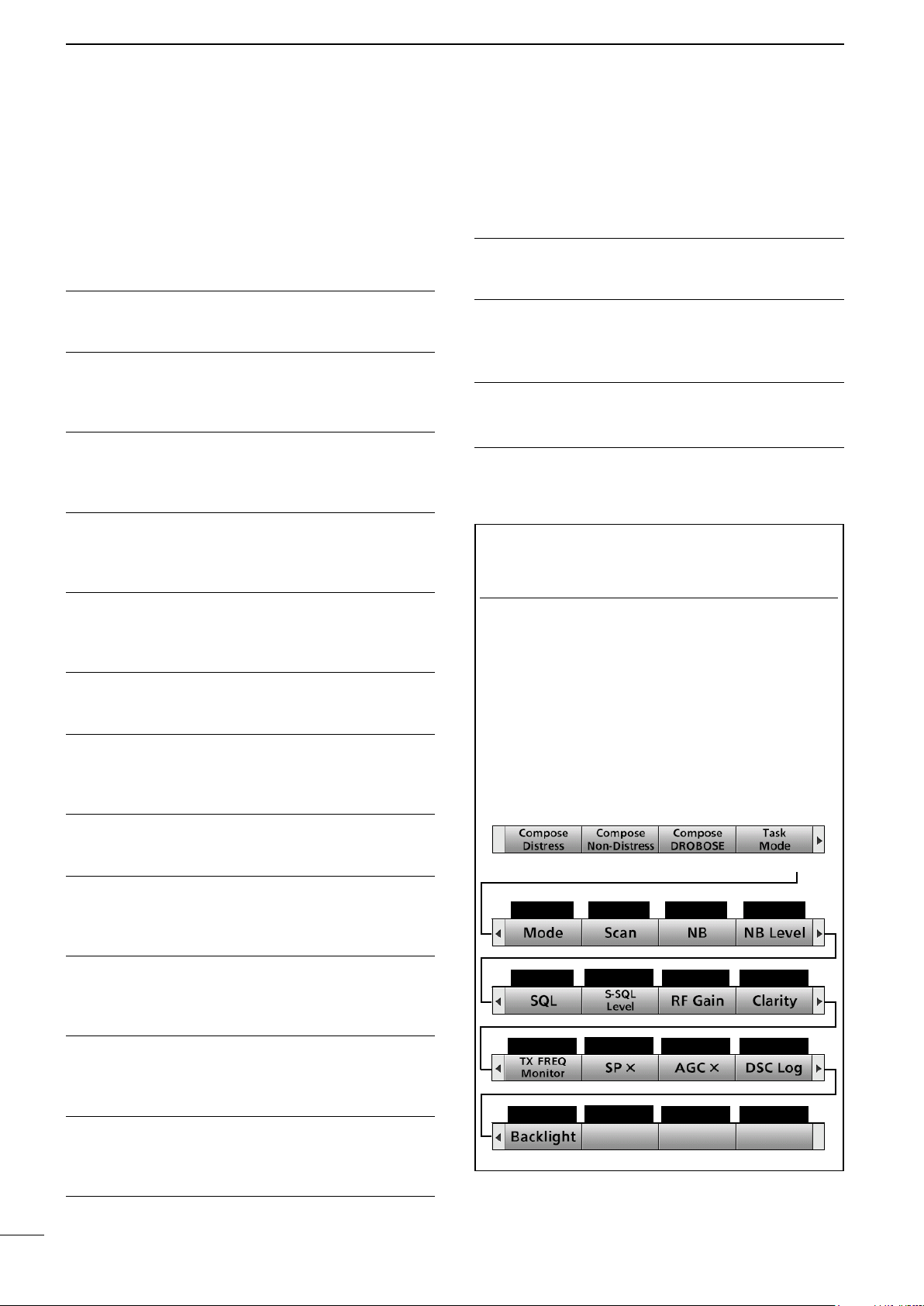
■Software Key function ...................... 4
DSelecting the Software Key
function........................................ 4
DFunctions..................................... 5
■Function display (Main screen) ........ 6
DStatus area .................................. 6
DInformation area .......................... 6
DChannel and Frequency area...... 6
DTask area..................................... 6
DPosition Date and Time area ....... 7
3. PREPARATION........................8
■Entering the MMSI code .................. 8
4. MENU SCREEN.................9–10
■Menu Construction........................... 9
■Selecting the item .......................... 10
5. BASIC OPERATION ........11–12
■Selecting a Channel or Group........ 11
DUsing the channel and group
selector...................................... 11
DUsing the keypad....................... 11
■Receiving and transmitting............. 12
DReceiving................................... 12
DTransmitting............................... 12
■DSC scan....................................... 12
6. OTHER FUNCTIONS AND
OPERATIONS..................13–22
■Backlight function........................... 13
■Scan............................................... 14
DChannel scan and Channel
Resume scan ............................ 14
DProgrammed scan ..................... 14
■Other functions............................... 15
DTransmit Frequency Monitor
function...................................... 15
DSquelch function........................ 15
DS-meter squelch level................ 15
DNoise Blanker function .............. 15
DNoise blanker level .................... 15
DAutomatic Gain Control OFF ..... 16
DRF gain level ............................. 16
DClarity Control function .............. 16
D
Automatic Antenna Tuner function
.. 16
■Setting a temporary operating
frequency ....................................... 17
■Setting a User channel or an ITU
Simplex channel............................. 18
■Assigning a function....................... 20
DAssigning a Software Key function
to a Software Key ...................... 20
DAssigning a Software Key function
to [VOL] ..................................... 21
DAssigning a Software Key
function to [P] on the HM-214H
microphone������������������������������� 22
7. DSC OPERATION............23–74
■DSC adress ID ............................... 23
DEntering an Individual ID ........... 23
DEntering a Group ID .................. 25
DDeleting an entered ID .............. 26
■Entering position data and time ..... 27
■DSC Task mode ............................. 29
DAbout “Active” and “Hold” .......... 29
DSoftware Key functions.............. 29
■Sending a Distress call .................. 30
DSimple call ................................. 30
DRegular call ............................... 31
DResending a Distress call.......... 33
DSending a Distress Cancel call.. 34
DSending a Distress
acknowledgement ..................... 36
DSending a Distress Relay call.... 37
DSending a Distress Relay
acknowledgement ..................... 42
■Sending a Non-Distress calls......... 43
DSending an Individual call.......... 43
D
Sending an Individual
acknowledgement ...................... 45
DSending a Group call................. 45
DSending a Geographical call ..... 47
DSending a Position Request call 50
DSending a Position Request
acknowledgement ..................... 51
DSending a Polling Request
acknowledgement ..................... 52
DSending a Test call .................... 52
DSending a Test call
acknowledgement ..................... 53
DSending a Medical Transports call
or Ships and Aircraft call............ 54
■Receiving DSC calls ...................... 57
DReceiving a Distress Call .......... 57
DReceiving a Distress
acknowledgement ..................... 58
DReceiving a Distress Cancel call59
DReceiving a Distress Relay call . 59
DReceiving a Distress Relay
acknowledgement ..................... 60
DReceiving an Individual call ....... 61
DReceiving an Individual
acknowledgement ..................... 61
DReceiving a Group call .............. 63
DReceiving a Geographical Area
call ............................................. 64
DReceiving a Position Request Call
.. 65
DReceiving a Position Request
acknowledgement ..................... 65
DReceiving a Polling Request call66
DReceiving a Test call.................. 66
DReceiving a Test
acknowledgement ..................... 67
DReceiving a Medical Transports call
67
D
Receiving a Ships and Aircraft call
. 68
■Received Call log ........................... 69
DDistress message...................... 69
DOther messages ........................ 69
■Transmitted Call log ....................... 69
■DSC Settings ................................. 70
DDSC Frequency......................... 70
DAutomatic acknowledgement .... 71
DSetting the “Medical Transports”
item display option..................... 72
DSetting the “Ships and Aircraft”
item display option..................... 72
DDistress Scanning Receiver ...... 72
DSetting the 10 Second Delay..... 73
DSetting the Alarm Status............ 73
DAuto Print................................... 74
DDSC Loop Test .......................... 74
8. MENU ITEMS...................75–77
■Menu items .................................... 75
■Radio Settings................................ 75
■Conguration.................................. 76
9. CONNECTIONS AND
INSTALLATION................78–86
■Supplied accessories ..................... 78
■Basic connections .......................... 78
■Advanced connections .................. 79
■Ground connection......................... 80
■Software maintenance ................... 80
■Power source ................................. 81
■Antenna.......................................... 81
■Mounting ........................................ 82
DMounting location ...................... 82
DAttaching the mounting plates .. 82
DMounting the remote controller . 82
DMounting the main unit .............. 82
■Using the optional MB-108............. 83
■Replacing fuses ............................. 84
■Connector information.................... 85
■Transceiver dimensions ................. 86
10. SPECIFICATIONS AND
OPTIONS .........................87–88
11. TROUBLESHOOTING...........89
12. DIGITAL INTERFACE
(IEC 61162-1) ...................90–93
■I/O Sentences ................................ 90
DVersion number ......................... 90
D
GPSInputsentences(IEC61162-1)
.................................................. 90
DGPS Input sentence description 90
DRemote Input and Out
putsentences(IEC61162-1)...... 91
DRemote sentence description.... 91
■Schematic diagram ........................ 92
■Hardware version........................... 93
■Software version ............................ 93
INDEX...........................................94

1
1
2001 NEW 2001 NEW
OPERATING RULES
• CALL PROCEDURE
Calls must be properly identied and the time limit
must be respected.
1. Give your call sign each time you call another
ship or coast guard station. If you have no call
sign, identify the station by giving your ship name
and the name of the licensee.
2. Give your call sign at the end of each
transmission that lasts more than 3 minutes.
3. You must break and give your call sign at least
once every 15 minutes during long ship-to-shore
calls.
4. Keep your unanswered calls short, less than 30
seconds. Do not repeat a call for 2 minutes.
5. Unnecessary transmissions are not allowed.
• PRIORITIES
1. Read all rules and regulations pertaining to
priorities and keep an up-to-date copy handy.
Safety and Distress calls take priority over any
other calls.
2. False or fraudulent Distress signals are prohibited
and punishable by law.
• PRIVACY
1. Information overheard but not intended for you,
cannot lawfully be used in any case.
2. Indecent or profane language is prohibited.
• LOGS
1. All Distress, Emergency and Safety calls must
be recorded in complete details. Log data activity
is usually recorded for 24 hours. Universal Time
Coordinated (UTC) is frequently used.
2. Keep adjustments, repairs, channel frequency
changes and authorized modications affecting
electrical operation of the equipment in the
maintenance log. The entries requires signatures
by the authorized licensed technician performing
or supervising the work.
• RADIO LICENSES
(1) SHIP RADIO STATION LICENSE
You need a current ship radio station license before
using the transceiver. It is unlawful to operate a ship
radio station which is not licensed, but required to be.
If required, contact your dealer or the appropriate
government agency for a Ship-Radiotelephone
license application. This government-issued license
states the call sign which is your craft’s identication
for radio communication purposes.
(2) OPERATOR’S LICENSE
A Restricted Radiotelephone Operator Permit is
the license most often held by small vessel radio
operators when a radio is not required for safety
purposes.
If required, the Restricted Radiotelephone Operator
Permit must be posted or kept with the operator. If
required, only a licensed radio operator may operate
a transceiver.
However, non-licensed individuals may talk over a
transceiver if a licensed operator starts, supervises,
ends the call and makes the necessary log entries.
A current copy of the applicable government rules
and regulations is only required to be on hand for
vessels in which a radio telephone is compulsory.
However, even if you are not required to have these
on hand it is your responsibility to be thoroughly
acquainted with all pertinent rules and regulations.
NOTE: Before transmitting, monitor the channel you
want to use to avoid interrupting communications
already in progress.

2
2001 NEW
1
2
3
4
5
6
7
8
9
10
11
12
13
14
15
16
17
Quick Reference
2
PANEL DESCRIPTION
17
16
15
14
13
12
10
11
9
7
8
6
5
4
3
2
Quick Reference
■Main unit
q GROUND TERMINAL [GND]
Connect to the ship’s ground. (p. 81)
w DSC ANTENNA CONNECTER
Connect to a 50 Ω HF marine band antenna
through a 50 Ω coaxial cable with a PL-259 plug.
This antenna is used for receiving Distress calls.
NOTE: To receive a Distress call, BE SURE
to connect an HF marine band antenna to this
antenna connector. Otherwise, you cannot
receive any Distress calls.
e SPEAKER JACK [SP]
Connect to the SP-24 (p. 80) or an external
speaker.
NOTE:
When using an external speaker, BE
SURE to turn OFF the internal speaker.
(p. 5)
Audio is output from the external speaker only
when the internal speaker is OFF.
r GPS JACK [GPS]
Connect to a GPS receiver to input position and
UTC data for DSC operations. (IEC 61162-1
Edition 4.0 (2010-11))
• An IEC 61162-1 Edition 4.0 (2010-11) (sentence
formatters: GGA) compatible GPS receiver is
required. Ask your dealer about suitable GPS
receivers.
GPS IN (+)
RCA
GPS IN (–)
t CONTROLLER CONNECTOR [CONTROLLER]
Connect to the supplied controller.
yMODEM SOCKET [AF/MOD] (p. 87)
Connect to an external terminal unit for SSB
mode operation through an RS-232C cable
(D-sub 15-pin).
u REMOTE SOCKET [REMOTE] (p. 88)
Connect to a PC through an RS-232C cable
(D-sub 9-pin) for remote control.
i PRINTER CONNECTOR
Connect to an IBM®centronics or compatible
printer to automatically or manually print out
received DSC information.
o ANTENNA CONNECTOR
Connect to a wire or whip antenna through the
AT-141
hf automatic antenna tuner
. The
antenna is used for transmitting any calls and
receiving any calls other than Distress calls.
RWARNING! NEVER directly connect the
antenna to this connector.
!0 TUNER CONTROL SOCKET [TUNE]
Connect to the control cable of the supplied
AT-141
hf automatic antenna tuner
. A female
connector kit is supplied to connect the AT-141.
!1 POWER SWITCH [DC ISOLATE]
Turns the transceiver’s main power ON or OFF.
When the main power is ON, the power key's
backlight is dimly lit.
!2 DC POWER TERMINALS
Connect to a 24 V DC power source through the
supplied DC power cables. The red terminal is
positive (+) and the black terminal is negative (–).
q
t
!2 !1
!0
oiuyrw e
FERRITE EMI FILTER FERRITE EMI FILTER

3
2001 NEW 2001 NEW
PANEL DESCRIPTION
2
■ Remote Controller front panel
qDISTRESS KEY [DISTRESS]
Hold down for 3 seconds to transmit a Distress
call. (p. 30)
w ENTER KEY [ENT]
Push to set the entered data, selected item, and
so on.
e LEFT AND RIGHT KEYS [Ω]/[≈]
Push to scroll the Software Key functions.
(p. 4)
In the Character or Number Entry mode, push
to select a character or number in the table.
r UP AND DOWN KEYS [∫]/[√]
Push to select an operating channel, menu items,
menu settings, and so on.
t KEYPAD
Push to enter numbers, letters or symbols.
y TUNE KEY [TUNE]
Push to turn ON the Automatic Antenna Tuner
function, or to go through (bypass) the tuning
circuit. (p. 16)
Hold down to start manual tuning.
L After tuning is completed, “TUNE” is displayed.
L When the tuner cannot tune the antenna, “THRU”
is displayed.
u POWER KEY [ ]
Hold down for 1 second to turn the transceiver
ON or OFF.
i VOLUME DIAL [VOL]
Rotate to adjust the speaker volume level.
Push 1 ~ 5 times to display the setting screens.
Pushing once The Volume Setting window is
displayed.
Pushing twice
The NB Level Setting window is
displayed.
Pushing 3 times
The S-SQL Level Setting window
is displayed.
Pushing 4 times
The RF Gain Setting window is
displayed.
Pushing 5 times
The Backlight Settings window is
displayed.
o RX/TX KEY [RX/TX]
Push to set a temporary operating frequency. (p. 17)
!0 DSC SCAN KEY [D-SCAN]
Push to start a DSC scan. (p. 12)
!1 CLEAR KEY [CLR]
Push to cancel the entered data, or to return to
the previous screen.
!2 CHANNEL/GROUP SELECTOR [CH/GRP]
Push to select the Channel Select mode or the
Group Select mode. (p. 11)
Push to set the entered data, selected item,
and so on.
Rotate to select the operating channel, menu
items, menu settings, and so on.
!3 MENU KEY [MENU]
Push to enter or exit the Menu screen.
q w e r
t
y
u
i
o
!0
SPEAKER FUNCTION DISPLAY (p. 6)
SOFTWARE KEYS (p. 4)MIC CONNECTOR !1!2!3

4
2001 NEW
2
2
PANEL DESCRIPTION
17
16
15
14
13
12
11
10
9
8
7
6
5
4
3
1
Quick Reference
■Handset
Speaker
Handset connector
Cradle
Speaker switch
PTT switch [PTT]
Microphone
DAbout the Speaker Switch
When the switch is set to the “ ” position:
You can hear the receive audio from the remote
controller's speaker.
When the switch is set to the “ ” position:
Mutes the remote controller speaker output.
• You can hear the receive audio from the handset.
Put the handset into the cradle to output the hear
audio from the remote controller's speaker.
■ Software Key function
The transceiver has Software Keys for various
functions. The key's function is displayed above
them, as shown below.
DSelecting the Software Key function
When “Ω” or “≈” is displayed beside the key icon,
pushing [Ω] or [≈] scrolls the Software Key functions.
When you push [Ω] or [≈] once, 4 functions scroll
together.
q PTT SWITCH
Hold down to transmit, release to receive.
w UP/DOWN KEYS [▲]/[▼]
Push to select an operating channel or group.
ePROGRAMMABLE KEY [P]
Push to activate the preset Software Key function.
Ask your dealer for details.
You can reassign some Software Key functions to
the key. (p. 20)
r DSC SCAN KEY [D-SCAN]
Push to start the DSC scan. (p. 12)
■ Optional HM-214H
qPTT SWITCH
[PTT]
w UP/DOWN
KEYS [▲]/[▼]
ePROGRAMMABLE
KEY [P]
MICROPHONE
r [D-SCAN]
Push [≈]
Push [≈]Push [Ω]
Push [Ω]
Push [Ω]
Push [≈]
Push [≈]
Push this Software Key to
compose a Distress call.

5
2001 NEW 2001 NEW
2PANEL DESCRIPTION
DFunctions
You can use various Software Key functions that are
assigned to the Software Keys, as described below.
Compose Distress
Push to compose a Distress call. (pp. 30 ~ 42)
Compose Non-Distress
Push to compose DSC calls other than Distress calls.
(pp. 43 ~ 56)
Compose DROBOSE
Push to compose a Distress Relay On Behalf Of
Someone Else (DROBOSE) call. (p. 37)
Task Mode
When the transceiver has any DSC tasks, push to
enter the DSC Task mode. (p. 29)
Mode
Push to select the J3E, H3E, LSB, J2B, F1B, or A1A
operating mode.
Scan
Push to start or stop a scan. (p. 14)
NB
Push to turn the Noise Blanker (NB) function ON or
OFF. (p. 15)
NB Level
Push to adjust the NB level. (p. 15)
SQL
Push to turn the Squelch function ON or OFF.
(p. 15)
S-SQL Level
Push to adjust the S-meter Squelch (S-SQL) level.
(p. 15)
RF Gain
Push to adjust the Radio Frequency (RF) gain level.
(p. 16)
Clarity
Push to turn the Clarity Control function ON or OFF.
(p. 16)
TX Freq Monitor
Push to check and monitor the transmit frequency.
(p. 15)
SP ×
Push to turn the speaker output ON or OFF.
AGC ×
Push to
turn the Automatic Gain Control (AGC)
function ON or OFF. (p. 16)
DSC Log
Push to check the received DSC calls. (p. 69)
Backlight
Push to change the brightness of the backlight.
(p. 13)
TIP: You can reassign the functions’ place to meet
your needs. (Soft Key 5 ~ Soft Key 20). For details
about how to assign them, see page 20.
InformationL
The rst set of Software Key functions ([Compose
Distress], [Compose Non-Distress],
[Compose DROBOSE], and [Task Mode]) are xed
and cannot be reassigned.
Push [►] to select the second set (Soft Key 5 ~ Soft
Key 8), the third set (Soft Key 9 ~ Soft Key 12), the
forth set (Soft Key 13 ~ Soft Key 16), and the fth
set (Soft Key 17 ~ Soft Key 20) of Software Key
functions.
Push [≈]
Soft Key 5 Soft Key 6 Soft Key 7 Soft Key 8
Soft Key 9 Soft Key 10 Soft Key 11 Soft Key 12
Soft Key 13 Soft Key 14 Soft Key 15 Soft Key 16
Soft Key 17 Soft Key 18 Soft Key 19 Soft Key 20
■Software Key function

6
2001 NEW
2
3
4
5
6
7
8
9
10
11
12
13
14
15
16
17
1
Quick Reference
2
PANEL DESCRIPTION
e Information area
r Channel and
Frequency area
q Status area
u Position Date and Time area
■Function display (Main screen)
DInformation area
The 9 digit MMSI (Maritime Mobile Service Identity:
DSC self ID) code and the following indications are
displayed in the Information area.
Indication Description
Displayed when receiving a signal or
when the squelch is open.
Displayed while transmitting.
Displayed when the GPS receiver is
activated and valid position data is
received.
Blinks while invalid position data is
being received.
Blinks when there is an unread DSC
message.
Displayed when the internal speaker is
OFF.
DStatus area
Indication Description
Scan Displayed during a scan.
NB Displayed when the Noise Blanker
function is ON.
SQL Displayed when the Squelch function is
ON.
Displayed when the AGC function is
OFF.
DChannel and Frequency area
Indication Description
Displayed when the Channel Select
mode is selected.
Displayed when the Group Select mode
is selected.
Displayed when the Clarity function is
ON. The number displays the added or
subtracted frequency.
SIMP Displayed when a Simplex channel is
selected.
DUP Displayed when a Duplex channel is
selected.
J3E/H3E/
LSB/J2B/
F1B/A1A
Displays the selected operating mode.
DTask area
Up to 7 task icons are displayed in the Task area
when the transceiver has a task.
Indication Description
Displayed while in the Radio Telephone
(RT) mode.
• “ ” is displayed when the RT mode task
is activated.
• Disappears if no operation occurs during
the preset period of time.
Displayed after receiving a DSC call.
• “ ” is displayed when the RX call task is
activated.
Displayed after making a DSC call.
• “ ” is displayed when the TX call task is
activated.
Display area Description
qStatus area Displays the current status.
wTask area Displays up to 7 task icons.
eInformation
area
Displays various icons and the
MMSI code.
rChannel and
Frequency area
Displays the selected
operating channel information.
tS/RF Meter • Displays the relative signal
strength of the receive
signal.
• Displays the output power
level of the transmit signal.
ySoftware Key
area
Displays the key function for
each Software Key.
u Position Date
and Time area
Displays the current position,
date and time.
y Software Key area
w Task area
t

2001 NEW
7
2001 NEW 2001 NEW
2PANEL DESCRIPTION
■Function display (Main screen)
DPosition Date and Time area
POSITION AREA
The current position is displayed when valid GPS
data is received, or when you manually enter your
position.
Indication Description
NO
POSITION
Displayed when a GPS receiver is
not connected and the position has
not been manually entered.
?? Blinks every 2 seconds instead of the
position when the GPS position data
is invalid.
• The last position is held for only 23.5
hours. After that, “NO POSITION” will be
displayed.
Blinks every 2 seconds instead of the
position after 4 hours have passed
since you manually entered the
position.
• The manually entered position is held
for only 23.5 hours. After that, “NO
POSITION” will be displayed.
DATE AND TIME AREA
• The current time is displayed when valid GPS data
is received, or manually enter the time.
• The date information is displayed when the RMC
GPS sentence formats are included in the GPS
signal.
Indication Description
NO TIME Displayed when a GPS receiver is not
connected and the time has not been
manually entered.
Local Displayed when the offset time is set.
Manual Displayed when the time is manually
entered.
UTC Displayed when the GGA, GLL or GNS
GPS sentence formats are included in
the GPS signal.
?? Blinks every 2 seconds instead of the
time when the GPS current time is
invalid.
• After 23.5 hours has passed, “NO TIME”
will be displayed.
Blinks every 2 seconds instead of the
time after 4 hours have passed since
you manually entered the time.
• The manually entered time is held for only
23.5 hours. After that, “NO TIME” will be
displayed.

8
2001 NEW
2
3
2001 NEW
17
16
15
14
13
12
11
10
9
8
7
6
5
4
1
Quick Reference
PREPARATION 3
■Entering the MMSI code
First, you must enter your 9 digit MMSI (Maritime
Mobile Service Identity: DSC self ID) code at power
ON.
You can perform this initial code entry ONLY
ONCE. After entry, only your dealer or distributor
can change it. If you have already entered your
MMSI code, these procedures are not necessary.
Example: Entering the MMSI code (123456789).
1. Hold down [ ] for 1 second to turn ON the
transceiver.
• Three short beeps sound.
• “ Push [ENT] to Register Your MMSI” is displayed.
2. Push [ENT].
NOTE: Push [CLR] to cancel the entry. In that case,
the transceiver displays “Push [ENT] to Register Your
MMSI” again.
3. Enter your 9 digit MMSI code.
4. After entering the 9th digit, push [ENT].
• The MMSI CONFIRMATION screen is displayed.
5. Reenter your MMSI code to confirm.
6. After entering the 9th digit, push [ENT].
• The MMSI code is registered.
NOTE:
When you successfully enter your MMSI code, the
following screen is displayed.
After that, the Main screen is displayed.
The registered MMSI code is displayed at the top of the
screen.
Push
+
Rotate
to select
a character
CH/GRP
Rotate
+
Push
CH/GRP
Push
+
Rotate
to select
a character
CH/GRP
Rotate
+
Push
CH/GRP
InformationL
Rotate CH/GRP : Rotate [CH/GRP] to select.
Push : Push [ENT] to enter or set.
Push : Push the keypad keys to enter a
digit or text.

2001 NEW
9
2001 NEW 2001 NEW
MENU SCREEN
4
■Menu Construction
You can use the Menu screen to set infrequently
changed values or function settings.
The Menu screen is constructed in a tree structure.
You can go to the next tree level by pushing [ENT], or
go back a level by pushing [CLR]. See the next page
for details.
To select an item, rotate [CH/GRP].
Compose Distress
Nature of Distress
Position
•Latitude
•Longitude
• UTC
Mode
Attempt
Compose Non-Distress
Message Type
Address*1
Area*1
•Latitude*1
•Longitude*1
•Radius*1
• Behind You*1
• To Your Right*1
Category
Call Frequency
• RX Frequency
• TX Frequency
Mode*1
Comm Frequency*1
• RX Frequency*1
• TX Frequency*1
DSC Settings
Position Input*2
Individual ID
Group ID
DSC Frequency
Individual ACK
Position ACK
Polling ACK
Test ACK
Medical Transports
Ships and Aircraft
Distress Scanning Receiver
10 Second Delay
Alarm Status
• Safety
•Routine
• Warning
• Self-Terminate
•Discrete
Auto Print
DSC Loop Test
Radio Settings
User CHAN
ITU Simplex CHAN
Max User CHAN
Auto Tune
Scan
Voice SQL
Conguration
Key Beep
NMEA Data Output
• DSC Data Output
Assignment
UTC Offset
Inactivity Timer
• Not DSC Related
•DSC Related
• RT Related-J3E/
H3E/LSB/J2B/F1B/
A1A
•Distress Related
MIC Key
Software Version
Compose DROBOSE
Message Type
Address
Area*1
•Latitude*1
•Longitude*1
•Radius*1
• Behind You*1
• To Your Right*1
Distress ID
Nature of Distress
Position
•Latitude
•Longitude
• UTC
Call Frequency
• RX Frequency
• TX Frequency
Mode
Comm Frequency
• RX Frequency
• TX Frequency
DSC Log
Received Call Log
•Distress
• Others
Transmitted Call Log
Rotate
CH/GRP
*1 These items may not be displayed, depending on
the “Message Type” option.
*2 This item is not displayed when valid GPS data is
received.

10
2001 NEW
4
2001 NEW
17
16
15
14
13
12
11
10
9
8
7
6
5
3
2
1
Quick Reference
MENU SCREEN 4
■Selecting the item
Follow the procedures described below to select a
Menu item.
Example: Turning ON the Voice Squelch function.
1. Push [MENU].
2. Select “Radio Settings.”
3. Select “Voice SQL.”
4. Select “On.”
• Returns to the “RADIO SETTINGS” screen.
5. Push [MENU] to return to the Main screen.
Rotate
+
Push
CH/GRP
Rotate
+
Push
CH/GRP
Rotate
+
Push
CH/GRP
InformationL
You can use the following key functions in the MENU
screen.
FUNCTION ACTION
Select Rotate [CH/GRP], or
Push [∫] or [√]
Enter Push [ENT],
Push [CH/GRP], or
Push [Enter]
Go to the next
tree level
Push [ENT] or
Push [≈]
Go back to the
previous tree
level
Push [CLR],
Push [Ω], or
Push [Back]
Cancel Push [CLR]
Exit Push [Exit]
Rotate CH/GRP : Rotate [CH/GRP] to select.
Push : Push [ENT] to enter or set.
Push : Push the keypad keys to enter a
digit or text.

2001 NEW
11
2001 NEW 2001 NEW
BASIC OPERATION
5
DUsing the keypad
•When selecting a User channel
1. Push the keypad keys to enter the channel
number.
2. Push [ENT] to set.
Example
• Selecting CH 41: [4
ghi
] → [1] → [ENT]
•
Selecting CH 128:
[1] → [2
abc
] → [8
tuv
] → [ENT]
•When selecting an ITU duplex channel
1. Push the keypad keys to enter the channel
number.
2. Push [ENT] to set.
Example
• Selecting CH 401: [4
ghi
] → [0] →[1]→ [ENT]
• Selecting CH 2505: [2
abc
] → [5
Jkl
] →[0] →
[5
Jkl
] → [ENT]
NOTE:
• See the Channel and Channel Group list below.
• Pushing [CLR] clears the entered digits and return to the
previous channel.
•When selecting an ITU simplex channel
1. Push the keypad keys to select a frequency band.
2.
Push the left most Software Key to enter “– ”
(dash).
3. Push the keypad keys to enter the channel
number.
4. Push [ENT] to set.
Example
•Selecting CH 4-1:[4
ghi
] → →[1]→ [ENT]
•Selecting CH 25-2: [2
abc
] → [5
Jkl
] → →
[2
abc
] → [ENT]
DUsing the channel and group selector
1. Push [CH/GRP] to toggle the Channel Select
mode or the Group Select mode.
• “ ” or “ ” is displayed.
2. Rotate [CH/GRP] to select a channel or group.
Example
When selecting the Group Select mode, the User
channels change in 20 channel steps.
NOTE: See the Channel and Channel Group list
below.
[CH/GRP]
• Channel Select mode • Group Select mode
■Selecting a Channel or Group
Push
[ENT]
KEY PAD
[CLR]
[CH/GRP]
[CLR]
• Channel and Channel Group list
Channel No. Description Channel No. Description Channel No. Description
1 ~ 160
401 ~ 429
4-1 ~ 4-9
601 ~ 608
6-1 ~ 6-9
801 ~ 837
8-1 ~ 8-9
User CH*
4 MHz ITU duplex CH
4 MHz ITU simplex CH
6 MHz ITU duplex CH
6 MHz ITU simplex CH
8 MHz ITU duplex CH
8 MHz ITU simplex CH
1201 ~ 1241
12-1 ~ 12-9
1601 ~ 1656
16-1 ~ 16-9
1801 ~ 1815
18-1 ~ 18-9
2201 ~ 2253
12 MHz ITU duplex CH
12 MHz ITU simplex CH
16 MHz ITU duplex CH
16 MHz ITU simplex CH
18 MHz ITU duplex CH
18 MHz ITU simplex CH
22 MHz ITU duplex CH
22-1 ~ 22-9
2501 ~ 2510
25-1 ~ 25-9
C1-1 ~ C1-21
C2-1 ~ C2-31
22 MHz ITU simplex
CH
25 MHz ITU duplex CH
25 MHz ITU simplex
CH
C1 channels
C2 channels
*[GRP] changes in 20 channel steps.
Selected frequency band is
briefl y displayed.

12
2001 NEW
5
2001 NEW
5
BASIC OPERATION
1
2
3
4
6
7
8
9
10
11
12
13
14
15
16
17
Quick Reference
■Receiving and transmitting
DReceiving
1. Select a channel by rotating [CH/GRP], or
pushing the keypad keys. (p. 11)
2. When receiving a call, rotate [VOL] to adjust the
audio output level.
TIP:
When a call is received:
•The icon is displayed.
• You can hear receive audio from the speaker.
• The S-meter displays the received signal strength.
DTransmitting
1. Select a channel by rotating [CH/GRP] or pushing
the keypad keys. (p. 11)
2. Push [Ω] or [≈] to display “TX FREQ Monitor” in
the Software Key area.
3. Hold down [TX FREQ Monitor] to temporarily
monitor the transmit frequency of the selected
channel.
• The transmit frequency is displayed and blinks.
NOTE: If the channel is busy, wait until it becomes
clear, or change to another channel.
4. Hold down [PTT] on the handset to transmit.
• is displayed.
NOTE: If “SWR” is displayed during the transmission,
check your antenna system.
5. Speak into the microphone at your normal voice
level.
6. Release [PTT] to receive.
• is displayed.
NOTE: For the Time-out Timer (TOT) function
The TOT function inhibits continuous transmission
beyond a preset time period after the transmission
starts. 10 seconds before transmission is cut off, a
beep sounds to indicate the transmission will be cut
off. Release [PTT] once to end your transmission
and reset the timer. You cannot transmit for 10
seconds after it is cut off.
IMPORTANT: To maximize the readability of your
transmitted signal, pause for a second after pushing
[PTT], and then hold the handset 5 to 10 cm from
your mouth and speak at your normal voice level.
[Ω]/[≈]
[CH/GRP]Software Keys
KEY PAD
■DSC scan
To receive a DSC call, such as an Individual call or a
Group call, push [D-SCAN] to enter the DSC watch
mode.
DSC watch mode
NOTE: The following frequencies are always
automatically monitored with this transceiver.
2187.5, 4207.5, 6312.0, 8414.5, 12577.0, and
16804.5 kHz
[D-SCAN]
[VOL]
Software Keys

2001 NEW
13
2001 NEW 2001 NEW
1. Push [Ω] or [≈] until “Backlight” is displayed in the
Software Key area.
2. Push [Backlight] to open the Backlight
setting window.
3. Push [▲] or [▼] to select “Day Mode” or “Night
Mode.”
In the Backlight Setting window, if you push no key
for about 5 seconds, the transceiver automatically
returns to the Main screen.
Day mode
Night mode
4. Rotate [CH/ENT] to adjust the backlight level,
then push [ENT].
The backlight level is adjustable in 7 levels and
“OFF.” “OFF” is selectable only in the Day mode.
Push
Rotate
+
Push
CH/GRP
OTHER FUNCTIONS AND OPERATIONS
6
■Backlight function
The function display and keys can be backlit for
better visibility under low light conditions.
You can set the Backlight mode to Day mode or Night
mode. The Day mode is for the daytime operation,
and the screen items are in color. The Night mode is
for the nighttime operation, and the screen items are
in black and red.
Information
Rotate CH/GRP : Rotate [CH/GRP] to select.
Push : Push [ENT] to enter or set.
Push : Push the keypad keys to enter digits
or text.

14
2001 NEW
1
2
3
5
6
7
8
9
10
11
12
13
14
15
16
17
Quick Reference
2001 NEW
4
OTHER FUNCTIONS AND OPERATIONS 6
17
16
15
5
14
12
13
11
10
9
8
7
6
2
3
1
Quick Reference
■Scan
DChannel scan and Channel Resume
scan
Channel scan and Channel Resume scan channels
within a 20 channel range, such as Ch 1 to Ch 20,
Ch 141 to Ch 160, and so on, in user channels, or all
channels in the group of ITU channels.
Ch 1
Ch 2 Ch 3
Ch 4
Ch 20
1. Rotate [GRP/CH] to select a channel group.
(p. 11)
2. Push [Ω] or [≈] until “Scan” is displayed in the
Software Key area.
3. Push [Scan] to start a scan.
4. Push [Scan] again to stop the scan.
DProgrammed scan
The Programmed scan scans frequencies in the
frequency range between user channels.
Ch 159 Ch 160
1. Push [Ω] or [≈] until “SQL” is displayed in the
Software Key area.
2. Push [SQL] to turn OFF the squelch
function.
3. Push [Ω] or [≈] until “Scan” is displayed in the
Software Key area.
4. Push [Scan] to start a scan.
5. Push [Scan] again to stop the scan.
Channel scan:
The scan does not
pause, even if a signal
is received.
Channel Resume
scan:
The scan pauses for
10 seconds, then
resumes, or resumes
after 2 seconds from
when the signal
disappears.
Example:
Scans the frequencies
between channels 159
and 160.
Scans quickly when
the squelch is closed.
Scans slowly when the
squelch is open.
The transceiver has automatic channel or frequency
scan capabilities (Scan function). There are 3 types
of scan functions.
• Channel scan
• Channel Resume scan
• Programmed scan
Select a scan type in the Menu screen.
See page 76 for details.

15
2001 NEW 2001 NEW
OTHER FUNCTIONS AND OPERATIONS
6
■Other functions
DSquelch function
The Squelch function mutes unwanted signals such
as noise or unmodulated beat signals. This function
enables quiet standby.
However, when you need to receive weak signals,
adjust the Squelch level, or turn OFF the function.
1. Push [Ω] or [≈] until “SQL” is displayed in the
Software Key area.
2. Push [SQL] to turn the function ON or OFF.
When the function is ON, is displayed.
DS-meter squelch level
When the Squelch function is ON, only signals
stronger than this set level are received.
Set to between 1 (open) and 100 (tight).
1. Push [Ω] or [≈] until “S-SQL Level” is displayed
in the Software Key area.
2. Push [S-SQL Level]
•The S-SQL level setting window is displayed.
3. Rotate [CH/GRP] to adjust the S-meter squelch
level.
DNoise Blanker function
The Noise Blanker function reduces pulse-type
noises that come from engine ignitions.
However, when the received strong signals are
distorted, adjust the Noise blanker level or turn OFF
the function.
1. Push [Ω] or [≈] until “NB” is displayed in the
Software Key area.
2. Push [NB] to turn the function ON or OFF.
When the function is ON, “NB” is displayed.
DNoise blanker level
When the Noise Blanker function is ON, adjust the
Noise blanker level to reduce various pulse-type
noises.
Set to between 1 and 10.
1. Push [Ω] or [≈] until “NB Level” is displayed in
the Software Key area.
2. Push [NB Level] .
•The NB level setting window is displayed.
3. Rotate [CH/GRP] to adjust the Noise Blanker
level.
DTransmit Frequency Monitor function
When selecting a duplex channel, the transmit
frequency differs from the receive frequency.
To prevent from interference to other stations, the
transmit frequency should be monitored before you
transmit.
1. Push [Ω] or [≈] until “TX FREQ Monitor” is
displayed in the Software Key area.
2. Hold down [TX FREQ Monitor] to monitor
the transmit frequency.
“ ” blinks and the transmit frequency is
displayed.
This manual suits for next models
1
Table of contents
Other Icom Transceiver manuals
Popular Transceiver manuals by other brands

Technisonic Industries Limited
Technisonic Industries Limited TiL-91-DE/S Installation and operating instructions

Dahua
Dahua OTS102T user manual

Hytera
Hytera PT350 Quick reference guide

Transition
Transition TN-SFP Series user guide

Kenwood
Kenwood TH-79A instruction manual

Kenwood
Kenwood TS-850S Service manual