8
BASIC MANUAL
1
2
3
1
2
3
ENGLISH
3
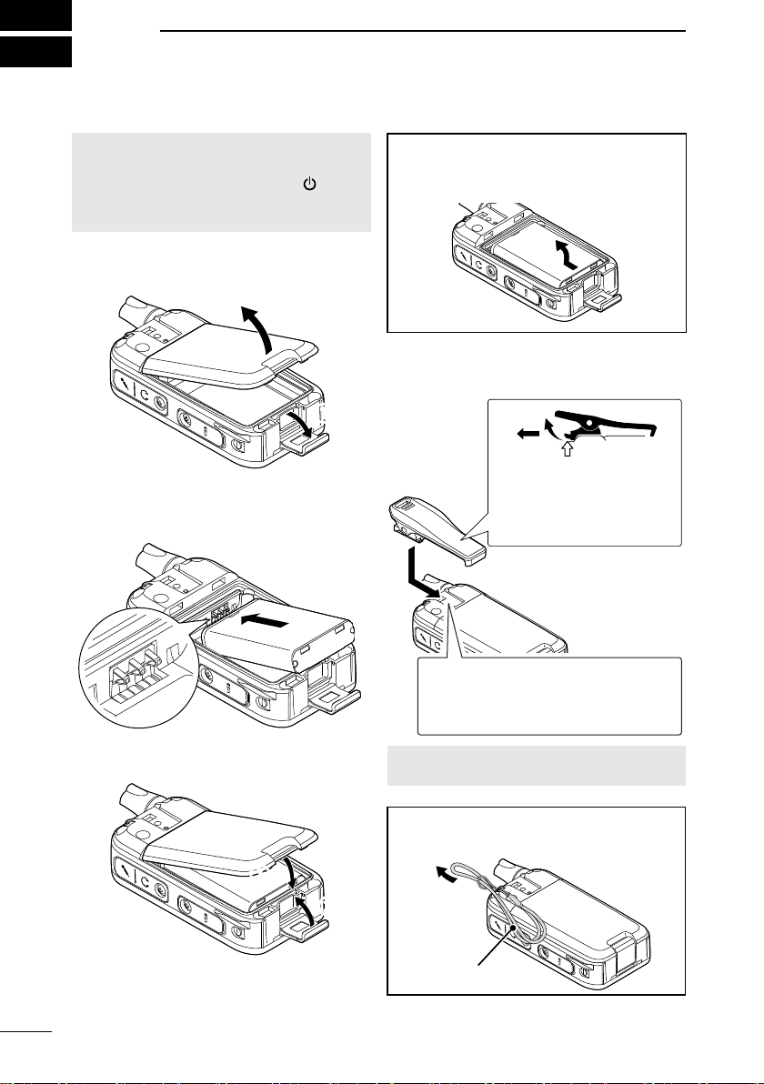
BATTERY CHARGING
Misuse of Li-ion batteries may result in
the following hazards: smoke, re, or
the battery may rupture. Misuse can
also cause damage to the battery or
degradation of battery performance.
RDANGER! NEVER incinerate used
battery packs. Internal battery gas may
cause an explosion.
RDANGER! NEVER solder the battery
terminals, or NEVER modify the battery
pack. This may cause heat generation, and
the battery may burst, emit smoke or catch
re.
RDANGER! NEVER leave battery packs
in places with temperatures above 60°C.
High temperature buildup in the battery
cells, such as could occur near res or
stoves, inside a sun-heated vehicle, or in
direct sunlight for long periods of time may
cause the battery cells to rupture or catch
re. Excessive temperatures may also
degrade the battery pack’s performance or
shorten the battery cell’s life.
RDANGER! NEVER strike or otherwise
impact the battery pack. Do not use
the battery pack if it has been severely
impacted or dropped, or if the pack has
been subjected to heavy pressure. Battery
pack damage may not be visible on the
outside of the case. Even if the surface of
the battery does not show cracks or any
other damage, the cells inside the battery
may rupture or catch re.
RDANGER! NEVER place battery packs
near a re. Fire or heat may cause them to
rupture or explode. Dispose of used battery
packs in accordance with local regulations.
RDANGER! NEVER let uid from inside
the battery get in your eyes. This can
cause blindness. Rinse your eyes with
clean water, without rubbing them, and
immediately go to a doctor.
RWARNING! NEVER Iet uid from inside
the battery cells come in contact with your
body. If it does, immediately wash with
clean water.
RWARNING! NEVER put the battery
pack in a microwave oven, high-pressure
container, or in an induction heating cooker.
This could cause a re, overheating, or
cause the battery cells to rupture.
RWARNING! NEVER use deteriorated
battery packs. They could cause a re.
CAUTION: DO NOT continue to use the
battery pack if it emits an abnormal odor,
heats up, or is discolored or deformed. If
any of these conditions occur, contact your
Icom dealer or distributor.
CAUTION: DO NOT expose the battery
pack to rain, snow, saltwater, or any other
liquids. Do not charge or use a wet pack. If
the pack gets wet, be sure to wipe it with a
clean dry cloth before using.
CAUTION: DO NOT use the battery pack
out of the specied temperature range for
the transceiver (–20°C ~ +60°C). Using
the battery out of its specied temperature
range will reduce its performance and
battery cell’s life.
CAUTION: DO NOT leave the pack fully
charged, completely discharged, or in an
excessive temperature environment (above
50°C) for an extended period of time. If
the battery pack must be left unused for
a long time, it must be detached from the
transceiver after discharging. You may
use the battery pack until the remaining
capacity is about half, then keep it safely
in a cool and dry place at the following
temperature range:
–20°C ~ +50°C (within a month)
–20°C ~ +40°C (within three months)
–20°C ~ +20°C (within a year)
■Battery cautions