Icom ID-1 User manual

INSTRUCTION MANUAL
ID-1
DIGITAL TRANSCEIVER
MIC
TD/RD PWR TX/RX POWER
TRANSCEIVER
ID-1
DIGITAL
New2001

i
New2001
FOREWORD
Thank you for purchasing this Icom product. The ID-1 digi-
tal transceiver is designed and built with Icom’s superior
technology and craftsmanship. With proper care, this product
should provide you with years of trouble-free operation.
We want to take a couple of moments of your time to thank
you for making your ID-1 your radio of choice, and hope you
agree with Icom’s philosophy of “technology first.” Many
hours of research and development went into the design of
your ID-1.
DFEATURES
❍Current FM, Digital Voice and Data modes
available
❍Standard PC control application via USB
terminal connection
❍
Remote controller for current mobile trans-
ceiver style operation (optional for some versions)
❍Standard 10BASE-T connector for data
transmission/reception
IMPORTANT
READ ALL INSTRUCTIONS carefully and completely
before using the transceiver.
SAVE THIS INSTRUCTION MANUAL— This in-
struction manual contains important operating instructions for
the ID-1.
EXPLICIT DEFINITIONS
WORD DEFINITION
RWARNING!
CAUTION
NOTE
Personal injury, fire hazard or electric shock
may occur.
Equipment damage may occur.
Recommended for optimum use. No risk of
personal injury, fire or electric shock.
Icom, Icom Inc. and the logo are registered trademarks of Icom
Incorporated (Japan) in the United States, the United Kingdom, Ger-
many, France, Spain, Russia and/or other countries.
Microsoft, Windows and Windows Vista are registered trademarks
or trademarks of Microsoft Corporation in the United States and/or
other countries.
All other products or brands are registered trademarks or trademarks
of their respective holders.

RWARNING RF EXPOSURE! This device emits
Radio Frequency (RF) energy. Extreme caution should be ob-
served when operating this device. If you have any questions re-
garding RF exposure and safety standards please refer to the
Federal Communications Commission Office of Engineering and
Technology’s report on Evaluating Compliance with FCC Guide-
lines for Human Radio frequency Electromagnetic Fields (OET
Bulletin 65).
RWARNING! NEVER connect the transceiver to an
AC outlet. This may pose a fire hazard or result in an electric
shock.
RWARNING! NEVER operate the transceiver while
driving a vehicle. Safe driving requires your full attention—any-
thing less may result in an accident.
RWARNING! NEVER transmit without an operational
antenna for 1.2 GHz operation. Transmission into a shorted or
non resonant antenna may damage the transceiver.
RWARNING for data mode operation! The
saved file(s) in the shared folder may be modified or deleted,
or unknown file(s) may be copied into the shared folder from
the connected station when the transmission inhibit is re-
leased.
Icom Inc. assume no responsibility whatsoever for any dam-
ages or lost profits resulting from opportunities for signal com-
munications being lost because of the failure, malfunction,
poor condition, damage, or data loss of this unit or because
of such external causes as power failure. Icom also dismisses
all responsibility for demands made by a third party.
NEVER cut the DC power cable between the DC plug and
fuse holder. If an incorrect connection is made after cutting, the
transceiver may be damaged.
NEVER connect the transceiver to a power source of more
than 16 V DC. This will damage the transceiver.
NEVER connect the transceiver to a power source using re-
verse polarity. This will damage the transceiver.
NEVER expose the transceiver to rain, snow or any liquids.
The transceiver may be damaged.
NEVER operate or touch the transceiver with wet hands. This
may result in an electric shock or damage to the transceiver.
NEVER place the transceiver where normal operation of the
vehicle may be hindered or where it could cause bodily injury.
NEVER let objects impede the operation of the cooling fan
on the rear panel.
ii
PRECAUTION

iii
New2001
PRECAUTION
DO NOT push the PTT when not actually desiring to trans-
mit.
DO NOT allow children to play with any radio equipment con-
taining a transmitter.
During mobile operation, DO NOT operate the transceiver
without running the vehicle’s engine. When the transceiver’s
power is ON and your vehicle’s engine is OFF, the vehicle’s bat-
tery will soon become exhausted.
BE CAREFUL! The transceiver will become hot when op-
erating it continuously for long periods.
AVOID using or placing the transceiver in direct sunlight or in
areas with temperatures below –10°C (+14˚F) or above +60°C
(+140˚F).
AVOID the use of chemical agents such as benzine or alcohol
when cleaning, as they can damage the transceiver’s surfaces.
USE Icom microphones only (supplied or optional). Other man-
ufacturer’s microphones have different pin assignments and may
damage the transceiver if attached.
DO NOT use the supplied CD for any other devices.
The CD is for the ID-1 only.
If a connection cable is disconnected or has a loose connec-
tion during operation, an error may occur. Connect the con-
nectors correctly, and DO NOT touch the connectors during
operation.
For the operation of PC and peripheral devices, follow the in-
structions provided in the manuals which come with the PC
and peripheral devices.
This device may cause signal interference when used in a
domestic setting. When interference occurs, move this unit
as far as possible away from the affected device.
All copyrights associated with this manual and all intellectual
property rights associated with the hardware and software of
the ID-1 are held by Icom Inc.
Unauthorized reproduction or transmission of this manual, or
any part hereof, is prohibited.
The content of this manual, the hardware and software asso-
ciated with the ID-1, and the appearance of the ID-1 are all
subject to change without notice.
For U.S.A. only
CAUTION: Changes or modifications to this device, not
expressly approved by Icom Inc., could void your authority to
operate this device under FCC regulations.

iv
New2001
SUPPLIED ACCESSORIES
o !0
q
!2
ew
t y
u i
!1
r
qMicrophone………………………………………………… 1
wExternal speaker (SP-22)………………………………… 1
eEthernet cable coupler …………………………………… 1
rDC power cable (3 m; 9.8 ft) …………………………… 1
tUSB extension cable (1.5 m; 4.9 ft) …………………… 1
yEthernet cable (3 m; 9.8 ft) ……………………………… 1
uSelf-adhesive rubber feet………………………………… 1
iApplication CD …………………………………………… 1
oRemote controller (RC-24)* ……………………………… 1
!0Mounting bracket for remote controller*………………… 1
!1Mounting screws, nuts and washers*………………… 1 set
!2Mic extension cable (2.5 m; 8.2 ft)* …………………… 1
*Optional for some versions.

New2001
v
TABLE OF CONTENTS
FOREWORD…………………………………………………………… i
IMPORTANT…………………………………………………………i
EXPLICIT DEFINITIONS ………………………………………… i
PRECAUTION …………………………………………………… ii
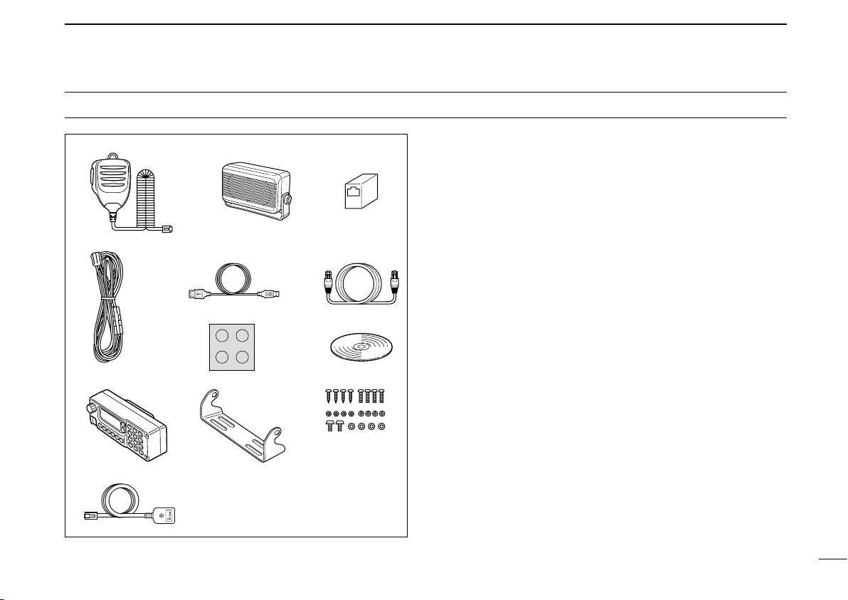
SUPPLIED ACCESSORIES …………………………………… iv
TABLE OF CONTENTS ………………………………………… v
1 PANEL DESCRIPTION …………………………………… 1–12
■Front panel ………………………………………………… 1
■Rear panel ………………………………………………… 2
■Microphone ………………………………………………… 3
■Application screens (on PC screen)……………………… 4
■Remote controller (RC-24; Optional for some versions) 9
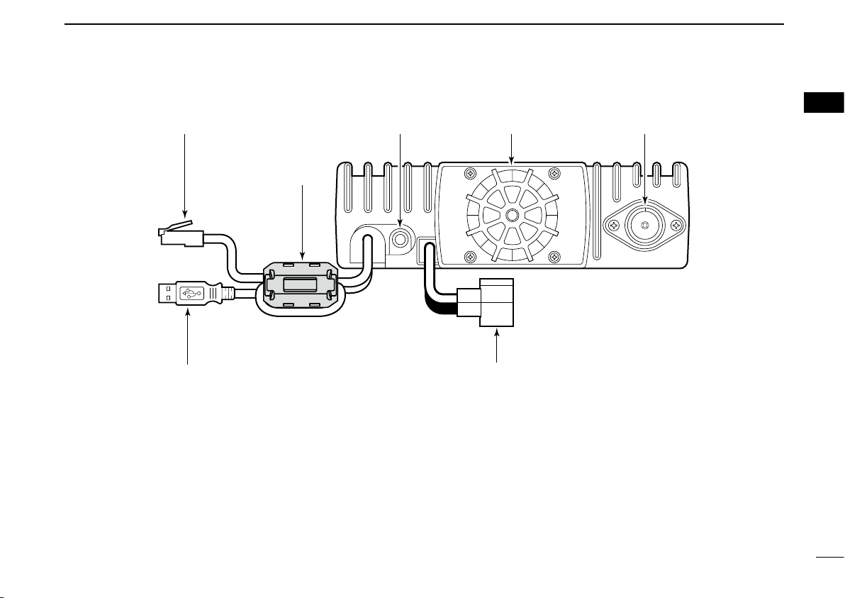
2 INSTALLATION AND CONNECTIONS ……………… 13–17
■Unpacking…………………………………………………… 13
■Selecting a location………………………………………… 13
■Antenna connection ……………………………………… 13
■Power supply connections ………………………………… 15
■Microphone and speaker connections …………………… 16
■Connecting a PC …………………………………………… 17
3 DRIVER INSTALLATION ……………………………… 18–29
■Microsoft®Windows®XP ………………………………… 18
■Microsoft®Windows®98/Me ……………………………… 22
■Microsoft®Windows®2000 ……………………………… 23
■COM port confirmation …………………………………… 28
4 APPLICATION INSTALLATION ……………………… 30–31
5 BASIC OPERATION …………………………………… 32–38
■Preparation ………………………………………………… 32
■Squelch level adjustment (FM mode only) ……………… 33
■Audio level adjustment …………………………………… 34
■VFO and memory mode…………………………………… 34
■Setting a frequency ………………………………………… 35
■Tuning step selection ……………………………………… 37
■Lock function (RC-24 only) ……………………………… 38
■Operating mode selection ………………………………… 38
6 CALL SIGN SETTING ………………………………… 39–44
■Your call sign setting ……………………………………… 39
■Station/Repeater call sign setting ………………………… 42
7 TRANSMIT AND RECEIVE— VOICE ………………… 45–54
■FM mode operation………………………………………… 45
■Digital voice mode operation ……………………………… 45
■When receiving a Digital call ……………………………… 47
■Short message function …………………………………… 49
■Monitor function …………………………………………… 53
8 REPEATER OPERATION— VOICE ………………… 55–63
■About D-STAR system …………………………………… 55
■General ……………………………………………………… 56
■Accessing an FM repeater………………………………… 57
■Repeater tone frequency setting ………………………… 59
■Offset frequency setting …………………………………… 60
■Accessing a Digital repeater ……………………………… 61
9 DATA OPERATION …………………………………… 64–70
■General ……………………………………………………… 64
■Precaution…………………………………………………… 64
■Internet access……………………………………………… 65
■Data transferring …………………………………………… 68
■Low-speed data communication ………………………… 70

New2001
vi
TABLE OF CONTENTS
10MEMORY/CALL OPERATION ………………………… 71–82
■General description ………………………………………… 71
■Memory channel selection ………………………………… 71
■Call channel selection……………………………………… 72
■Programming a memory/call channel …………………… 74
■Copying a memory contents ……………………………… 77
■Memory clearing …………………………………………… 78
■Programming memory name ……………………………… 80
■Memory name indication ………………………………… 82
11SCAN OPERATION …………………………………… 83–89
■Scan types ………………………………………………… 83
■Scan start/stop ……………………………………………… 84
■Programming scan edge channels ……………………… 85
■Skip channel setting ……………………………………… 88
■Scan resume condition …………………………………… 89
12PRIORITY WATCH ……………………………………… 90–91
■Priority watch types ………………………………………… 90
■Priority watch operation …………………………………… 90
13POCKET BEEP AND TONE/DIGITAL SQUELCH … 92–99
■Pocket beep operation …………………………………… 92
■Tone/Digital code/call sign squelch operation ………… 96
14OTHER FUNCTIONS ………………………………… 100–112
■Set mode ………………………………………………… 100
■EMR mode operation …………………………………… 107
■Break-in communication………………………………… 109
■S-meter squelch ………………………………………… 111
■AFC function……………………………………………… 111
■CPU reset ………………………………………………… 112
15MAINTENANCE ……………………………………… 113–114
■Troubleshooting ………………………………………… 113
■Fuse replacement ……………………………………… 114
16SPECIFICATIONS AND OPTIONS ………………… 115–116
■Specifications …………………………………………… 115
■Options …………………………………………………… 116
1
2
3
4
5
6
7
8
9
10
11
12
13
14
15
16

■Front panel
qMICROPHONE CONNECTOR [MIC]
Connects the supplied microphone or the remote control-
ler, RC-24 (optional for some versions).
qi
Front panel view
q +8 V DC output (Max. 100 mA)
wChannel up/down
eData out
rPTT
tGND (microphone ground)
yMIC (microphone input)
uGND
iData IN
wDATA TRANSMIT/RECEIVE INDICATOR
Lights green while receiving; lights red while transmitting
data in data mode.
ePOWER INDICATOR
Lights while the transceiver power is turned ON.
r TRANSMIT/RECEIVE INDICATOR
Lights green while receiving; lights red while transmitting
in FM/digital voice mode.
tPOWER SWITCH [POWER]
Turns power ON and OFF when pushed for 1 sec.
MIC
TD/RD PWR TX/RX POWER
TRANSCEIVER
ID-1
DIGITAL
q ew r t
1
PANEL DESCRIPTION
1
New2001

2
1
PANEL DESCRIPTION
1
■Rear panel
qETHERNET RECEPTACLE (p. 17)
Connects to a PC directly, or via an extension cable.
wEXTERNAL SPEAKER JACK [SP] (p. 16)
Connects the supplied (or optional) external speaker for
voice reception.
e COOLING FAN
The fan rotates when the internal temperature of the trans-
ceiver exceeds the preset value until the temperature drops.
Also runs while receiving depending on the setting in set
mode.
r
ANTENNA CONNECTOR (p. 13)
Connects a 50 Ωantenna with a type-N connector and a
50 Ωcoaxial cable.
tUSB RECEPTACLE
(p. 17)
Connects to a PC directly or via an extension cable.
y POWER RECEPTACLE
(p. 15)
Accepts 13.8 V DC ±15% with the supplied DC power
cable.
qe
wr
t
Ferrite core:
Supplied with
the European
versions only.
y

3
1PANEL DESCRIPTION
New2001
■Microphone
w
q
ON
OFF
e
qPTT SWITCH
Push and hold to transmit; release to receive.
wUP/DOWN SWITCHES [UP]/[DN]
Push either switch to change operating frequency, mem-
ory channel, etc.
eUP/DN LOCK SWITCH
Slide to toggle [UP]/[DN] switches function ON and OFF.

4
1
PANEL DESCRIPTION
New2001
1
■
Application screens (on PC screen)
DMain screen
*The application screen can be seen after the application
installation. See page 30 for details.
qFILE MENU
Click to display the file menu to perform the following op-
eration.
• Transceiver initialization
• Opening a file
• Saving (over-write or with different file name) the set con-
tents
• Reads the transceivers memory data (See NOTE on p. 6)
• Printing out the memory contents
• Quitting the application
wVIEW MENU
Click to display the view menu to display the following
screens or selections.
• Memory channel list screen
• Set mode screen
• Font size setting
• Tool bar indication ON/OFF
• My call sign screen
q w e r t
!0!1!2!4!5!6!7!8@0@1 !9@2 !3
y u i o

5
1PANEL DESCRIPTION
New2001
eOPTION MENU
Click the option menu to display and set the following
items.
• COM port setting screen
• “Wake up power ON” function
rHELP MENU
Click the help menu to display the following screen.
• Help file
• Application version information
tTOOL BAR
The following functions can be performed by clicking one
of the desired short cut button.
• Transceiver initialization
• Opening a file
• Saving the file
• Reads the transceivers memory data (See NOTE on p. 6)
• Displays memory channel list screen
• Displays set mode screen
yAUDIO VOLUME CONTROL [VOL]
Left clicking to decrease; right clicking to increase the
audio volume level.
uTRANSMIT INHIBIT BUTTON [TX inh]
Inhibits transmission during digital mode operation.
iAUDIO MUTE BUTTON [MUTE]
Mutes the audio output.
oFUNCTION BUTTONS
[CD] : Click to display and hide the Received call re-
cord screen.
[CS] : Click to display and hide the Select Call Sign
screen.
[LOW] : Click to select the transmit output power from
high and low.
[RP] : Click to select repeater shifting mode from RP–,
RP+, RPS and simplex (no indication).
[TONE] : During FM mode operation
Click to select tone condition from repeater
tone ON, tone squelch ON, pocket beep func-
tion ON and no tone operation.
[DSQL] : During Digital voice mode operation
Click to select squelch condition from digital
code squelch ON, digital call sign squelch ON,
pocket beep function ON and no digital squelch
operation.
[MW] : Click to display and hide the Memory program-
ming screen.
[PRIO] : Click to start and cancel priority watch function.
[SCAN] : Click to display the scan type selection screen.
After the scan type selection, starts the scan.
[MN] : Click to switch the memory name indication ON
and OFF during memory mode operation.
[BK] : Click to start break-in communication.
[AFC] : Click to turn the automatic frequency control
function ON and OFF.
[F.INP] : Click to display and hide the Keypad screen.

6
1
PANEL DESCRIPTION
New2001
1
!0 EMR MODE BUTTON [EMR]
Click to enter and exit EMR mode.
!1 MESSAGE BUTTON [MSG]
Click to turn the message screen indication ON and OFF.
!2 SQUELCH CONTROL [SQL]
Left click to decrease; right click to increase the squelch
level.
!3 SKIP BUTTON [SKIP]
During memory mode, click to turn the skip setting for the
selected memory channel ON and OFF.
!4 MONITOR BUTTON [MONI]
Click to turn the monitor function ON and OFF.
While the function ON, any squelches, such as tone
squelch, are released and emits audio.
!5 SET MODE BUTTON [SET]
Click to display and hide the Set mode screen.
!6 OPERATING MODE BUTTON [MODE]
Click to select the operating mode from FM, digital voice
(DV) and data (DD).
!7 CALL CHANNEL BUTTON [CALL]
Click to select a call channel (1–3).
!8 VFO/MEMORY MODE BUTTON [V/M]
Click to switch between VFO and memory mode.
!9 TUNING DIAL [DIAL]
Left click to decrease; right click to increase the operating
frequency or memory channel.
@0 TUNING STEP BUTTON [TS]
Click to display the tuning step list.
After the tuning step selection, the list disappears.
@1 1 MHz TUNING BUTTON [MHz]
Click to turn the 1 MHz tuning ON and OFF.
While the 1 MHz tuning is selected, “Z” icon appears.
@2 POWER BUTTON [POWER]
Click to turn the transceiver power ON and OFF.
Even the transceiver power is turned OFF, the control ap-
plication is still running.
NOTE: While reading the transceiver’s memory data
While reading the transceiver’s memory data the “ ” button
in the tool bar will change from Black to Red arrows.
It is not recommended to save data or initialize the trans-
ceiver while the program is downloading the memory channel
data. If transceiver initialization or save data buttons are acci-
dentally pushed, the dialog box shown below will appear.
It is recommended to click the cancel button to allow the task
of reading the transceiver to be completed. Then try the ini-
tialization or saving data. Completion of the download is indi-
cated when the arrows change from Red to Black.

7
1PANEL DESCRIPTION
New2001
DMemory channel list screen
qCHANNEL SELECT
Select the memory channel for operation by double click-
ing and select “Move to this channel”.
“+” appears when the channel is selected.
wPROGRAMMED FREQUENCY
Enter the desired operating frequency.
Select the desired frequency cell, then enter the desired
frequency from the PC’s keyboard directly.
eOPERATING MODE
To select the desired operating mode, double click the
mode cell. Then click to select the desired operating mode,
FM, DV (Digital Voice) or DD (Data mode).
rREPEATER
Select the desired shift direction for repeater operation
from RP–, RP+, RPS and Simplex in RP cell, and enter
the desired offset frequency via the PC’s keyboard within
0 to 60 MHz range in Offset Freq. cell.
RP– : Negative shift
RP+ : Positive shift
RPS : For repeater operation in DD mode
tTONE/TSQL
Select the desired tone function from TONE, TSQL and
OFF in Tone Select cell, and select the desired tone fre-
quency for each Repeater Tone and TSQL Tone from the
list appeared by double clicking the cell.
TONE : Repeater tone ON
TSQL : Tone squelch ON
q w e r yt u i o

8
1
PANEL DESCRIPTION
New2001
1
yDIGITAL
Select the desired digital squelch function from digital
code squelch, digital call sign squelch and OFF in DSQL
cell, and enter the desired digital code number within 00 to
99 range for the digital code squelch function.
DSQL : Digital call sign squelch ON
CSQL : Digital code squelch ON
uCALL SIGN
Enter the station’s call sign that you want to call into YOUR
cell, and repeater call sign into RPT1 and RPT2 cell.
iSKIP SETTING
Turn the skip function ON (SKIP) and OFF.
When ON is set, the memory channel will be skipped dur-
ing memory scan.
oMEMORY NAME
Enter the desired memory name.
Each name can have up to 10 characters.

9
1PANEL DESCRIPTION
New2001
■Remote controller (RC-24; Optional for some versions)
1294.500 00
DV RP-
qw
er t y u i o
Function display (p. 12) Keypad (pgs. 10, 11)
qTUNING DIAL [DIAL]
Selects the operating frequency (p. 35), memory channel
(p. 72), the setting of the set mode value or condition and
the scanning direction.
wUP/DOWN SWITCHES [ ]/[ ]
➥Adjusts the audio output level. (p. 34)
➥After pushing [SQL], adjusts squelch level. (p. 33)
eMICROPHONE CONNECTOR [MIC]
Connects the microphone, supplied with the transceiver.
rVFO/MEMORY SWITCH [V/M] (p. 34)
Push to toggle VFO and memory mode.
tCALL SWITCH [CALL] (p. 73)
Push to select and toggle call channel 1, 2 and 3.
yOPERATING MODE SWITCH [MODE] (p. 38)
Push to select an operating mode from FM, DV (Digital
Voice) and DD (Data mode).
uTRANSMIT INHIBIT•SET MODE SWITCH [TXinh• ]
➥Push to inhibits a transmission during DD mode.
(p. 67)
➥Push to enter the message indication mode during DV
mode. (p. 50)
➥Push for 0.5 sec. to enter set mode. (p. 100)
iSQUELCH SWITCH [SQL] (p. 33)
Push this switch then push either [ ] or [ ] switch to ad-
just the squelch level.

10
1
PANEL DESCRIPTION
New2001
1
oPOWER SWITCH [PWR] (p. 33)
Turns power ON and OFF when pushed for 0.5 sec.
DKeypad
[CS• •1]
➥Push to enter call sign select mode. (p. 40)
➥Push for 0.5 sec. to enter received call record
indication. (p. 47)
➥After pushing [F.INP•L], input digit “1” for op-
erating frequency or memory channel.
[MHz• •2]
➥Push to select 1 MHz tuning. (p. 35)
➥Push for 0.5 sec. to enter tuning step select-
ing condition. (p. 37)
➥After pushing [F.INP•L], input digit “2” for op-
erating frequency or memory channel.
[LOW•3]
➥Push to toggle low and high transmit output
power. (p. 45)
➥After pushing [F.INP•L], input digit “3” for op-
erating frequency or memory channel.
[RP•4]
➥Push to toggle repeater operating mode.
(pgs. 58, 61, 67)
➥After pushing [F.INP•L], input digit “4” for op-
erating frequency or memory channel.
[TONE• •5]
➥FM mode: Push to turn the repeater tone,
tone squelch and pocket beep function ON
and OFF.
➥DV Mode: Push to turn the digital call sign,
digital code squelch and pocket beep function
ON and OFF.
➥After pushing [F.INP•L], input digit “5” for op-
erating frequency or memory channel.
[MW•6]
➥Push to enter select memory write condition.
(p. 76)
➥After pushing [F.INP•L], input digit “6” for op-
erating frequency or memory channel.
[PRIO• •7]
➥Push to start and stop priority watch. (p. 91)
➥Push for 0.5 sec. to set the selected mem-
ory channel as a skip channel during memory
mode. (p. 88)
➥After pushing [F.INP•L], input digit “7” for op-
erating frequency or memory channel.
[SCAN•8]
➥Push to start and stop scanning. (p. 84)
➥After pushing [F.INP•L], input digit “8” for op-
erating frequency or memory channel.

11
1PANEL DESCRIPTION
New2001
[MN•9]
➥Push to select memory name or frequency in-
dication during memory mode. (p. 82)
➥After pushing [F.INP•L], input digit “9” for op-
erating frequency or memory channel.
[BK• •.]
➥Push to enable a break call during digital
voice operation. (p. 110)
➥Push for 0.5 sec. to select “CQ” as a call sign
during digital voice operation. (p. 46)
➥After pushing [F.INP•L], selects previous
“MHz” digits frequency for operating fre-
quency. (p. 36)
[AFC• •0]
➥Push to turn the AFC (Automatic Frequency
Control) function ON and OFF. (p. 111)
➥Push for 1.5 sec. to turn the EMR mode ON,
and push for 0.5 sec. to turn the function OFF
during digital voice mode operation. (p. 108)
➥After pushing [F.INP•L], input digit “0” for op-
erating frequency or memory channel.
[F.INP•L]
➥Push to enable the direct frequency or mem-
ory channel number input.
➥Push for 0.5 sec. to turn the RC-24 key lock
function ON and OFF. (p. 38)

12
1
PANEL DESCRIPTION
New2001
1
DFunction display
1294.500
FM RP-
M00
q
i
w e r t y u
qS/RF INDICATORS
➥Shows the relative signal strength while receiving sig-
nals in 3 steps.
➥Shows the output power level while transmitting.
wTRANSMIT INDICATOR
Appears while transmitting.
eBUSY INDICATOR
Appears when a signal is being received, the squelch is
open, or the monitor function is activated.
NOTE: If this indicator appears and no audio is heard it
is one of several conditions.
1. Verify audio level setting.
2. Verify connection of external speaker.
3. FM: Signal coming in, but does not match TSQL.
Digital Voice: Incoming signal does not match call signs
in the call sign squelch list.
rPOCKET BEEP INDICATORS (p. 94)
Appears when the pocket beep function is activated.
tLOCK INDICATOR (p. 38)
Appears when the lock function is in use.
yLOW POWER INDICATOR
Appears when low output power is selected.
uMESSAGE INDICATOR
Blinks when a message is received. (p. 51)
iMULTI-FUNCTION INDICATOR
Shows variety of information, such as the operating fre-
quency, operating mode, memory names, set mode item
and conditions.

13
New2001New2001
INSTALLATION AND CONNECTIONS
2
■Unpacking
After unpacking, immediately report any damage to the deliv-
ering carrier or dealer. Keep the shipping cartons.
For a description and a diagram of accessory equipment in-
cluded with the ID-1, see ‘Supplied Accessories’ on p. iv of
this manual.
■Selecting a location
Select a location for the transceiver that allows adequate air
circulation, free from extreme heat, cold, or vibrations, and
away from TV sets, TV antenna elements, radios and other
electromagnetic sources.
■Antenna connection
For radio communications, the antenna is of critical im-
portance, along with output power and sensitivity. Select
antenna(s), such as a well-matched 50 Ωantenna, and feed-
line. 1.5:1 or better of Voltage Standing Wave Ratio (VSWR)
is recommended for your desired band. Of course, the trans-
mission line should be a coaxial cable.
CAUTION: Protect your transceiver from lightning by using
a lightning arrestor.
NOTE: There are many publications covering proper an-
tennas and their installation. Check with your local dealer
for more information and recommendations.
•Antenna location for mobile operation
To obtain maximum performance from the transceiver, select
a high-quality antenna and mount it in a good location. A non-
radial antenna should be used when using a magnetic mount.
Roof-mount antenna
(Drill a hole or use a magnetic mount.)
Gutter-mount antenna
Trunk-mount
antenna
ID-1
To antenna
Other manuals for ID-1
3
Table of contents
Other Icom Transceiver manuals