Icom iF34GT User manual

INSTRUCTION MANUAL
iF44GT
UHF HANDHELD TRANSCEIVER
iF34GT
VHF HANDHELD TRANSCEIVER

i
EXPLICIT DEFENITIONS
WORD DEFINITION
RDANGER! Personal death, serious injury or an
explosion may occur.
RWARNING! Personal injury, fire hazard or electric
shock may occur.
CAUTION Equipment damage may occur.
NOTE
If disregarded, inconvenience only. No risk
of personal injury, fire or electric shock.
IMPORTANT
READ ALL INSTRUCTIONS carefully and com-
pletely before using the transceiver.
SAVE THIS INSTRUCTION MANUAL — This
instruction manual contains important operating instructions
for the IC-F34GT VHF TRANSCEIVER and IC-F44GT UHF
TRANSCEIVER.
Icom, Icom Inc. and the Icom logo are registered trademarks of Icom
Incorporated (Japan) in Japan, in the United States, the United Kingdom,
Germany, France, Spain, Russia and/or other countries.

RDANGER! NEVER short the terminals of the bat-
tery pack.
RWARNING! NEVER hold the transceiver so that
the antenna is very close to, or touching exposed parts of
the body, especially the face or eyes, while transmitting. The
transceiver will perform best if the microphone is 2 to 4 in. (5
to 10 cm) away from the lips and the transceiver is vertical.
RWARNING! NEVER operate the transceiver with a
headset or other audio accessories at high volume levels.
CAUTION: NEVER use non-Icom battery packs/
chargers to prevent the loss of the transceiver’s good per-
formance and warranty.
DO NOT push PTT when not actually desiring to transmit.
DO NOT use or place the transceiver in direct sunlight or
in areas with temperatures below +22°F (–30°C) or above
+140°F (+60°C).
The basic operations, transmission and reception of the
transceiver are guaranteed within the specified operating
temperature range. However, the LCD display may not be
operate correctly, or show an indication in the case of long
hours of operation, or after being placed in extremely cold
areas.
DO NOT modify the transceiver for any reason.
KEEP the transceiver away from the heavy rain, and
Never immerse it in the water. The transceiver construction
is water resistant, not waterproof.
PRECAUTION
ii

iii
TABLE OF CONTENTS
IMPORTANT...................................................................................... i
EXPLICIT DEFENITIONS ................................................................. i
PRECAUTION .................................................................................. ii
TABLE OF CONTENTS................................................................... iii
1 ACCESSORIES ......................................................................1−3
■ Supplied accessories...............................................................1
■ Accessory attachments ...........................................................1
2 PANEL DESCRIPTION .........................................................4−10
■ Front panel...............................................................................4
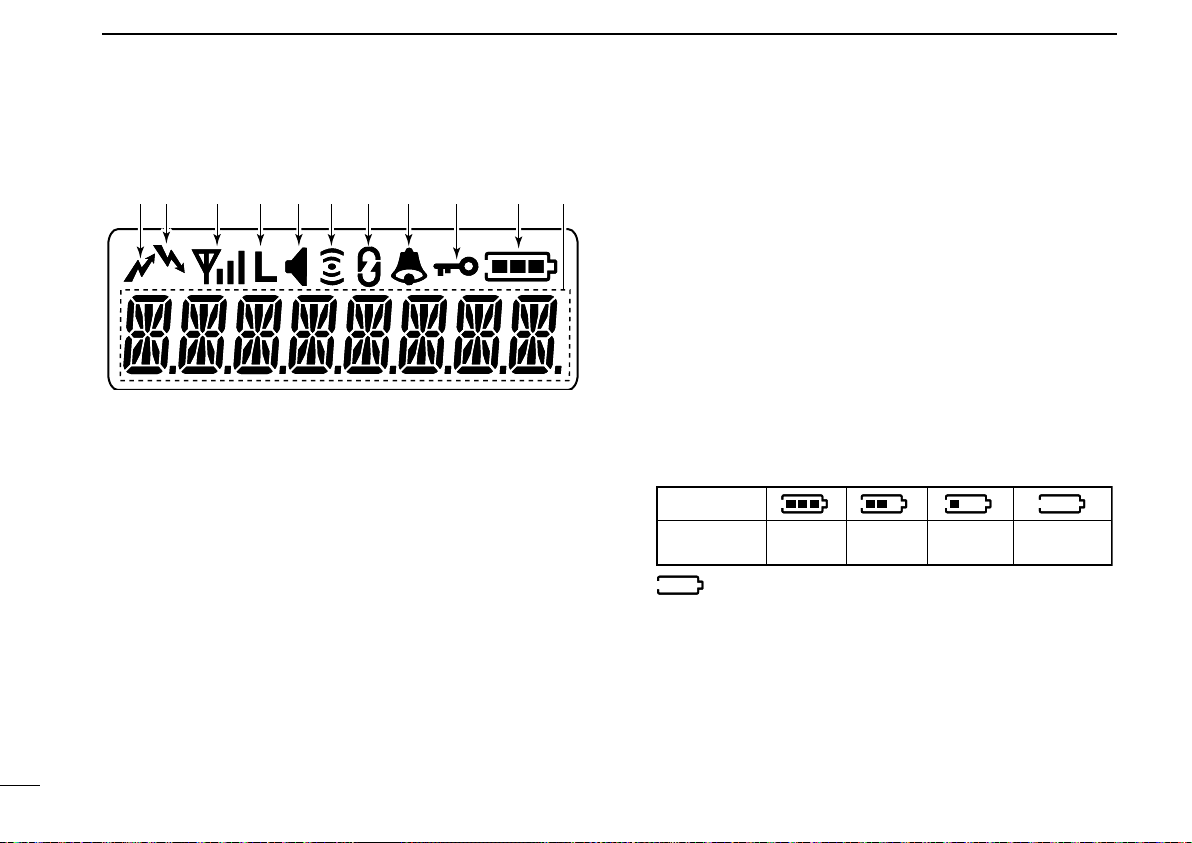
■ Function display.......................................................................6
■ Programmable function keys ...................................................7
3 BASIC OPERATION ...........................................................11−15
■ Turning power ON..................................................................11
■ Channel selection ..................................................................12
■ Call procedure .......................................................................12
■ Receiving and transmitting ....................................................13
■ User set mode .......................................................................15
■ Scrambler function.................................................................15
4 BIIS OPERATION ...............................................................16−26
■ Setting example .....................................................................16
■ Receiving a call......................................................................16
■ Transmitting a call .................................................................. 18
■ Receiving a message ............................................................20
■ Transmitting a status ..............................................................22
■ Transmitting an SDM.............................................................. 22
■ Position data transmission.....................................................24
■ Printer connection..................................................................24
■ Digital ANI..............................................................................24
■
Auto emergency transmission ................................................. 25
■ Stun function..........................................................................25
■ BIIS indication........................................................................25
■ Priority A channel selection ...................................................25
■ Man Down Emergency Call ...................................................26
5 MDC 1200 SYSTEM OPERATION .....................................27−32
■ MDC 1200 system operation .................................................27
■ Transmitting a call .................................................................. 27
■ Receiving a call......................................................................31
6 OPTIONAL UNIT INSTALLATION......................................33−34
■ Optional unit installation.........................................................33
■ UT-109 and UT-110 installation..............................................34
7 BATTERY CHARGING .......................................................35−38
■ Caution ..................................................................................35
■ Optional battery chargers ......................................................37
8 BATTERY CASE .......................................................................39
■ Optional battery case (BP-240) .............................................39
9 SWIVEL BELT CLIP ...........................................................40−41
■ MB-93 contents......................................................................40
■ To attach ................................................................................40
■ To detach ...............................................................................41
10 OPTIONS ............................................................................42−43

1
1
ACCESSORIES
■Supplied accessories
The following accessories are supplied: Qty.
qFlexible antenna...............................................................1
wBattery pack.....................................................................1
eBelt clip ............................................................................1
rUnit cover (double-sided tape)*........................................1
tJack cover (with screws) ............................................ 1 set
*Use the unit cover as a spare. Ask your dealer for details.
■Accessory attachments
DFlexible antenna
Connect the supplied flexible an-
tenna to the antenna connector.
CAUTION:
• NEVER HOLD the antenna
when carrying the transceiver.
• Transmitting without an antenna
may damage the transceiver.
qw
r
e
t
1
2
3
4
5
6
7
8
9
10
11
12
13
14
15
16

2
1ACCESSORIES
DBattery pack
To attach the battery pack:
Slide the battery pack on the back of the transceiver in the
direction of the arrow (q), then lock it with the battery re-
lease button.
• Slide the battery pack until the battery release button makes a
‘click’ sound.
To release the battery pack:
Push the battery release button in the direction of the arrow
(w) as shown below. The battery pack is then released.
NEVER release or attach the battery pack when the
transceiver is wet or soiled. This may result water or dust
getting into the transceiver/battery pack and may result in
the transceiver being damaged.
DBelt clip
To attach the belt clip:
qRelease the battery pack if it is attached.
wSlide the belt clip in the direction of the arrow until the belt
clip is locked and makes a ‘click’ sound.
To detach the belt clip:
qRelease the battery pack if it is attached.
wPinch the clip (q), and slide the belt clip in the direction
of the arrow (w).
q
w
q
w

3
1
ACCESSORIES
DJack cover
Attach the jack cover when the optional speaker-microphone
is not used.
CAUTION:
Attach the jack cover when the optional equipment is not
used. Otherwise the terminals of the [SP]/[MIC] jack may
be shorted by metal object, etc., and this could damage
the transceiver.
To attach the jack cover:
qAttach the jack cover on
the [SP]/[MIC] jack.
wTighten the screws.
To detach the jack cover:
qUnscrew the screws with
a Phillips screwdriver.
wDetach the jack cover for
the speaker-microphone
jack.
q
w
q
w
1
2
3
4
5
6
7
8
9
10
11
12
13
14
15
16

4
2PANEL DESCRIPTION
■Front panel
qROTARY SELECTOR
Rotate to select the pre-programmed memory channels
or the operating bank.
(Depending on the pre-setting)
wVOLUME CONTROL [VOL]
Rotate to turn the power ON/OFF and adjust the audio
level.
eDEALER-PROGRAMMABLE KEY [EMERGENCY]
Desired function is programmable by your dealer. (p. 7)
r[SP]/[MIC] JACK
Connect the optional speaker-microphone.
[SP]/[MIC] jack cover
NOTE: Attach the [SP]/[MIC] jack
cover when the optional speaker-
microphone is not used.
(See p. 3 for details)
tFUNCTION DISPLAY
Displays a variety of information such as an operating
channel number/name, 2/5-tone code, DTMF numbers,
selected function, etc.
yDEALER-PROGRAMMABLE KEYS [P0] to [P3]
Desired function is programmable independently by your
dealer. (p. 7)
t
r
q
e
u
y
w
i
o
!0
!1

5
2
PANEL DESCRIPTION
u10-KEYPAD (Depending on version)
The keypad allows you to enter digits to:
• Select memory channels
• Select tone channels
• Select DTMF codes (during transmission)
• Set TX codes
• Set BIIS status number
• Input text message for SDM operation
• Start up with the password
iUP/DOWN KEYS
Desired function is programmable by your dealer. (p. 7)
• [CH UP] and [CH DOWN] (p. 7) are assigned to each key as
the default.
oPTT SWITCH [PTT]
➥Push and hold to transmit; release to receive.
➥Push to transmit the call during MSK operation, de-
pending on the setting.
!0 MONITOR KEY
Desired function is programmable by your dealer. (p. 7)
• [MONITOR] (p. 8) is assigned as the default.
!1 ANTENNA CONNECTOR
Connects the supplied antenna.
1
2
3
4
5
6
7
8
9
10
11
12
13
14
15
16

6
2PANEL DESCRIPTION
■Function display
q!0!1oiuytrew
qTRANSMIT INDICATOR
Appears while transmitting.
wBUSY INDICATOR
Appears while the channel is busy.
eSIGNAL STRENGTH INDICATOR
Indicates relative signal strength level.
rLOW POWER INDICATOR
Appears when low output power is selected.
• When the battery power decreases to a specified level, low
power is selected automatically.
tAUDIBLE INDICATOR
➥Appears when the channel is in the ‘audible’ (unmute)
condition.
➥Appears when the matched signal is received.
yCOMPANDER INDICATOR
Appears when the compander function is activated.
uSCRAMBLER INDICATOR
Appears when the voice scrambler function is activated.
iBELL INDICATOR
Appears/blinks when the matched signal is received, ac-
cording to the pre-programming.
oKEY LOCK INDICATOR
Appears during the key lock function is ON.
!0 BATTERY INDICATOR
Appears or blinks when the battery power decreases to a
specified level.
Indication
Full Middle Charging
required No batteryBattery level
blinks when the battery is exhausted.
!1 ALPHANUMERIC DISPLAY
Displays an operating channel number, channel name,
Set mode contents, DTMF code, etc.

2
PANEL DESCRIPTION
■Programmable function keys
The following functions can be assigned to [UP], [DOWN],
[P0], [P1], [P2], [P3], [EMERGENCY] and [MONITOR] pro-
grammable function keys.
Consult your Icom dealer or system operator for details con-
cerning your transceivers programming.
If the programmable function names are bracketed in the fol-
lowing explanations, the specific key is used to activate the
function depends on the programming.
CH UP AND DOWN KEYS
➥ Push to select an operating channel. When [Rotary selec-
tor] selects “operating channel,” this key is not available.
➥ Push to select a transmit code channel after pushing [TX
Code CH Select].
➥ Push to select a DTMF channel after pushing [DTMF Au-
todial].
➥Push to select a scan group after pushing and holding
[Scan A Start/Stop]/[Scan B Start/Stop].
➥Push to select a BIIS code, status number or SDM after
pushing [Digital].
➥ Push to select the MDC menu after pushing [MDC CALL].
➥Push to select the desired transceiver alias or message
channel while in the transceiver alias or message channel
selection mode.
BANK SELECT KEY
Push this key, then push [CH Up] or [CH Down] to select
the desired bank. When [Rotary selector] selects “operating
bank,” this key operation is not available.
SCAN A KEY
➥Push to start and cancel scanning operation.
• When Power ON Scan function is activated, push to pause the
scanning operation. And the paused scan resumes after the
specified time period has passed.
➥Push and hold this key for 1 sec. to indicate the scan list,
then push [CH Up] or [CH Down] to select the desired list.
SCAN B KEY
➥Push to start and cancel scanning operation.
The scan restarts after the specified time period has
passed when the scan (started with this key) is canceled
by except for this key operation.
➥
Push and hold this key for 1 sec. to indicate the scan list,
then push [CH Up] or [CH Down] to select the desired list.
SCAN ADD/DEL (TAG) KEY
Push to add channel to, or delete it from the current scan
group.
7
1
2
3
4
5
6
7
8
9
10
11
12
13
14
15
16

8
2PANEL DESCRIPTION
PRIORITY CHANNEL KEYS
➥Push to select Priority A or Priority B channel.
➥ Push and hold [Prio A (Rewrite)] to rewrite the Prio A
channel.
MR-CH 1/2/3/4 KEYS
Push to select the memory channels 1 to 4 directly.
LOCK KEY
➥Push and hold for 1 sec. to electronically lock all program-
mable keys except the following:
[Call] (incl. Call A and Call B), [Moni(Audi)] and
[Emergency].
➥Push and hold for 1 sec. again to turn the lock function
OFF.
OUTPUT POWER SELECTION KEY
Push to select the transmit output power temporarily or per-
manently, depending on the pre-setting.
• Ask your dealer for the output power level for each selection.
C.TONE CHANNEL ENTER KEY
Push to select the continuous tone channel using [CH Up]/
[CH Down] to change the tone frequency/code setting after
pushing this key for permanent operation.
TALK AROUND KEY
Push to turn the talk around function ON and OFF.
• The talk around function equalizes the transmit frequency to the
receive frequency for transceiver-to-transceiver communication.
MONITOR KEY
➥Push to mute and release the CTCSS (DTCS) or 2-tone
squelch mute. Open any squelch/deactivate any mute
while pushing and holding this key. (LMR operation only)
➥Activates one of (or two of) the following functions on
each channel independently: (PMR or BIIS PMR opera-
tion only)
• Push and hold to un-mute the channel (audio is emitted;
‘Audible’ condition).
• Push to mute the channel (sets to ‘Inaudible’ only).
• Push to un-mute the channel (sets to ‘Audible’ only).
• Push after the communication is nished to send a ‘reset
code’.
NOTE: The un-mute condition (‘Audible’ condition) may
automatically return to the mute condition (‘Inaudible‘
condition) after a specified period.
WIDE/NARROW KEY
Push to toggle the IF bandwidth between wide and narrow.
• The wide passband width can be selected from 25.0 or 20.0 kHz
using the CS-F33G c l o n i n g s o f t wa r e . (PMR or BIIS PMR opera-
tion only) Ask your Dealer for details.
DTMF AUTODIAL KEY
➥Push to enter the DTMF channel selection mode.
Then select the desired DTMF channel using [CH Up]/
[CH Down] keys.
➥After selecting the desired DTMF channel, push this key
to transmit the DTMF code.

2
PANEL DESCRIPTION
DTMF RE-DIAL KEY
Push to transmit the last-transmitted DTMF code.
CALL KEYS
Push to transmit a 2/5-tone/BIIS ID code.
• Call transmission is necessary before you call another station
depending on your signalling system.
• [Call A] and/or [Call B] may be available when your system
employs selective ‘Individual/Group’ calls. Ask your dealer which
call is assigned to each key.
EMERGENCY KEYS
➥Push and hold for a speified period to transmit a
DTMF,
5-tone or MDC 1200 emergency signal*
.
* Depending on the operating model type.
➥ When [Emergency Single (Silent)] or [Emergency Repeat
(Silent)] is pushed, an emergency call is transmitted with-
out a beep emission and LCD indication change. (BIIS
operation only)
• If you want to cancel the emergency call, push (or push and
hold) the key again before transmitting the call.
• The emergency call is transmitted one time only or repeatedly
until receiving a control code depending on the pre-setting.
TX CODE ENTER KEY (PMR or BIIS PMR operation only)
Push to enter the direct ID code edit mode, for both
5-tone and MSK. Then set the desired digit using [CH Up]/
[CH Down]/[TX Code CH Up]/[TX Code CH Down] or
10-keypad. (p. 15)
TX CODE CHANNEL UP/DOWN KEYS
Push to select a TX code channel directly.
TX CODE CHANNEL SELECT KEY
➥Push to enter the direct ID code channel selection mode.
Then set the desired channel using [CH Up]/[CH Down]/
[TX Code CH Up] or [TX Code CH Down]. (p. 14)
➥ While in ID code channel selection mode, push for 1 sec.
to enter the ID code edit mode for 5-tone and MSK. Then
set the desired digit using [CH Up]/[CH Down]/[TX Code
CH Up]/[TX Code CH Down] or 10-keypad. (p. 14)
ID MEMORY READ KEY (PMR or BIIS PMR operation only)
➥Recalls detected ID codes.
• Push this key, then push [CH Up]/[CH Down] for selection.
• Up to 5 ID’s are memorized.
➥Push and hold to erase the selected memorized ID’s.
VOICE SCRAMBLER FUNCTION
Push to toggle the voice scrambler function ON and OFF.
9
1
2
3
4
5
6
7
8
9
10
11
12
13
14
15
16

10
2PANEL DESCRIPTION
COMPANDER KEY
Push to toggle the compander function ON and OFF.
The compander function reduces noise components from
the transmitting audio to provide clear communication.
USER SET MODE KEY
➥Push and hold for 1 sec. for to enter user set mode.
• During user set mode, push this key to select an item, and push
[CH Up]/[CH Down] to change the value or c ondition.
➥Push and hold this key for 1 sec. again to exit user set
mode.
OPT OUT KEYS
Push to control the optional unit connector output signal
level.
DIGITAL KEY (BIIS operation only)
➥Push to select the call ID list, transmit message and
standby condition. Toggles between queue channel and
received message record indication after queue channel
is selected.
➥Push and hold to select queue channel indication.
STATUS UP/DOWN KEYS (BIIS operation only)
➥ While in the standby condition, push to display the trans-
mit status indication and select a status number.
➥ When a received SDM is displayed, push to cancel the
automatic scroll and scroll the message manually.
➥ When an SDM that contains more than 8 characters is
displayed, push to scroll the message manually.
MDC CALL KEY (MDC operation only)
➥Push to enter the MDC menu selection mode. Then
select the desired MDC menu from “SELCALL,” “MSG,”
“STATUS,” “RADIOCHK” and “CALALERT” using [CH Up]/
[CH Down]/[MDC Up]/[MDC Down].
After selection, push this key again to enter the transceiv-
er alias or message channel selection mode.
➥
While in the transceiver alias or message channel selection
mode, push to return to the MDC menu selection mode.
• No operation is performed for about 15 sec., the transceiver
returns to the normal operation condition.
MDC UP AND DOWN KEYS (MDC operation only)
➥ Push to select the MDC menu after pushing [MDC CALL].
➥Push to select the desired transceiver alias or message
channel while in the transceiver alias or message channel
selection mode.
MDC SELCALL KEY (MDC operation only)
Push to enter the transceiver alias selection mode.
• After the desired alias selection, push [PTT] to transmit a SelCall.
• No operation is performed for about 15 sec., the transceiver
returns to the normal operation condition.
MDC CALLALERT KEY (MDC operation only)
Push to enter the transceiver alias selection mode.
• After the desired alias selection, push [PTT] to transmit a call alert.
• No operation is performed for about 15 sec., the transceiver
returns to the normal operation condition.

3
BASIC OPERATION
■Turning power ON
Prior to using the transceiver for the first time, the battery
pack must be fully charged for optimum life and operation.
(p. 35)
qRotate [VOL] to turn the power ON.
wIf the transceiver is programmed for a start up password,
input the digit codes as directed by your dealer.
• 10-keypad can be used for password input.
• The keys in the table below can be used for password input:
• The transceiver detects numbers in the same block as identical.
Therefore “01234” and “56789” are the same.
e When the “PASSWORD” indication does not clear after
inputting 4 digits, the input code number may be incorrect.
Turn the power off and start over in this case.
DBattery type selection
The battery type must be selected according to the attaching
battery type when tuning the transceiver ON.
➥ While pushing and holding [EMERGENCY] and [PTT], ro-
tate [VOL] to toggle the attaching battery type.
• After the display appears, release [EMERGENCY] and [PTT].
• “ DRY BATT” is displayed for about 3 sec. then “Lo” (low power
indicator) appears when the battery case operation is selected.
• “LI-ION” is displayed for about 3 sec. when the Lithium-ion bat-
tery operation is selected.
[EMERGENCY]
[PTT]
[VOL]
This operation may not be available depending on the pre-set-
ting. Ask your dealer for details.
KEY
NUMBER 0
5
4
9
3
8
2
7
1
6
DOWN
11
1
2
3
4
5
6
7
8
9
10
11
12
13
14
15
16

12
3BASIC OPERATION
■Channel selection
Several types of channel selections are available. Methods
may differ according to your system set up.
NON-BANK TYPE:
To select the desired operating channel:
• Push [CH Up] or [CH Down].
• Rotate [ROTARY SELECTOR]*.
- Up to pre-programmed 16 channels can be selected.
• Push one of [MR-CH 1] to [MR-CH 4].
BANK TYPE:
To select the desired bank:
• Push [Bank], then push [CH Up] or [CH Down].
• Rotate [ROTARY SELECTOR]*.
- Up to pre-programmed 16 banks can be selected.
AUTOMATIC SCAN TYPE:
Channel setting is not necessary for this type. When turning
power ON, the transceiver automatically starts scanning.
Scanning stops when receiving a call.
* Depending on the pre-setting.
When the [Rotary selector] activates as the “Operating channel”
selection, [CH Up]/[CH Down] are not available for the channel se-
lection.
When the [Rotary selector] activates as the “Operating bank” se-
lection, [Bank] is not available for the bank selection.
■Call procedure
When your system employs tone signaling (excluding CTCSS
and DTCS), the call procedure may be necessary prior to voice
transmission. The tone signalling employed may be a selective
calling system which allows you to call specific station(s) only
and prevent unwanted stations from contacting you.
qSelect the desired TX code channel or 2/5-tone code ac-
cording to your System Operator’s instructions.
• This may not be necessary depending on programming.
• Refer to page 14 or 15 for selection.
w Push [Call] (assigned to one of the dealer programma-
ble keys: [UP], [DOWN], [P0], [P1], [P2], [P3], [RED] and
[Monitor]) or [PTT].
eAfter transmitting a 2/5-tone code, the remainder of your
communication can be carried out in the normal fashion.
Selective calling Non-selective calling

3
BASIC OPERATION
■Receiving and transmitting
NOTE: Transmitting without an antenna may damage the
transceiver. See p. 1 for antenna attachment.
Receiving:
q Rotate [VOL] to turn the power ON.
w Push [CH UP] or [CH DOWN], or rotate [ROTARY SE-
LECTOR]* to select a channel, in sequence.
*Depending on the pre-setting.
e When receiving a call, adjust the audio output level to a
comfortable listening level.
Transmitting:
Wait for the channel to become clear to avoid interference.
q While pushing and holding [PTT], speak into the micro-
phone at a normal voice level.
w Release [PTT] to return to receive.
IMPORTANT: To maximize the audio quality of your signal;
1. Pause briey after pushing [PTT].
2. Hold the microphone 5 to 10 cm (2 to 4 inches) from
your mouth, then speak into the microphone at a nor-
mal voice level.
DTransmitting notes
• Transmit inhibit function
The transceiver has several inhibit functions which restrict
transmission under the following conditions:
- The channel is in mute condition (‘Inaudible’ condition;
“” does not appear.)
- The channel is busy.
- Un-matched (or matched) CTCSS is received.
(Depending on the pre-setting.)
- The selected channel is a ‘receive only’ channel.
• Time-out timer
After continuous transmission for the pre-programmed time
period, the time-out timer is activated, causing the trans-
ceiver to stop transmitting.
• Penalty timer
Once the time-out timer is activated, transmission is further
inhibited for a period determined by the penalty timer.
13
1
2
3
4
5
6
7
8
9
10
11
12
13
14
15
16

14
3BASIC OPERATION
DTX code channel selection
If the transceiver has [TX Code CH Select] assigned to it,
the indication can be toggled between the operating channel
number (or name) and TX code channel number (or name).
When the TX code channel number (or name) is displayed,
[CH UP]/[CH DOWN] selects the TX code channel.
USING [TX CODE CH SELECT] KEY:
q Push [TX Code CH Select]— a TX code channel number
(or name) appears.
w Push [CH Up] or [CH Down] to select the desired TX code
channel.
e After selecting, push [TX Code CH Select] to set.
• Return to the stand-by mode.
r Push [Call] to transmit the selected TX code.
USING [TX CODE CH UP]/[TX CODE CH DOWN] KEYS:
If the transceiver has a [TX Code CH Up] or [TX Code CH
Down] key assignment, the programmed TX code channel
can be selected directly when pushed.
DTX code number edit
(PMR or BIIS PMR operation only)
If the transceiver has [TX Code CH Select] or [TX Code
Enter] assigned to it, TX code contents can be edited within
the allowable digits.
USING [TX CODE CH SELECT] KEY:
q Push [TX Code CH Select] to enter the TX code channel
selection mode.
• Select the desired channel using [CH UP] or [CH DOWN] if
necessary.
w Push and hold [TX Code CH Select] for 1 sec. to enter
the TX code edit mode.
• The digit to be edited blinks.
e Push [TX Code CH Select] to select the desired digit to
be edited.
r Set the desired digit using [CH UP], [CH DOWN], [TX
Code CH Up], [TX Code CH Down] or 10-keypad.
t Push [TX Code CH Select] to set the digit. The digit to the
right will blink automatically.
• When the 10-keypad is used to set, the editable digit will move
to the right automatically without pushing [TX Code CH Select].
yRepeat rand tto input all allowable digits.
u After editing, push [TX Code CH Select] to set.
• Return to the stand-by mode.
i Push [Call] to transmit.

3
BASIC OPERATION
USING [TX CODE ENTER] KEY:
q Select the desired TX code channel via [TX Code CH Up]
or [TX Code CH Down].
w Push [TX Code Enter] to enter the TX code edit mode.
• The digit to be edited blinks.
e
Push [TX Code Enter] to select the desired digit to be edited.
r Set the desired digit using [CH UP], [CH DOWN], [TX
Code CH Up] or [TX Code CH Down] or 10-keypad.
t Push [TX Code Enter] to set the digit. The digit to the right
will blink automatically.
• When the 10-keypad is used to set, the editable digit will move
to the right automatically without pushing [TX Code Enter].
yRepeat rand tto input all allowable digits.
u After editing, push [TX Code Enter] to set.
• Return to the stand-by mode.
i Push [Call] to transmit.
DDTMF transmission
If the transceiver has [DTMF Autodial] assigned to it, the
automatic DTMF transmission function is available. Up to 8
DTMF channels are available.
TO SELECT A TX CODE:
q Push [DTMF Autodial]— a DTMF channel appears.
w Push [CH UP] or [CH DOWN] to select the desired DTMF
channel.
e Push [DTMF Autodial] to transmit the DTMF code in the
selected DTMF channel.
■User set mode
User set mode is accessed with [User Set Mode] and allows
you to set seldom-changed settings. In this case you can
“customize” the transceiver operation to suit your prefer-
ences and operating style.
Entering the user set mode:
q Push and hold [User Set Mode] to enter user set mode.
Push [User Set Mode] momentarily to select the item.
Then push [UP] or [DOWN] to set the desired level/condi-
tion.
• Available set mode functions are Backlight, Beep, SQL Level,
Mic Gain and Battery Voltage.
w Push and hold [User Set Mode] to exit user set mode.
■Scrambler function
The voice scrambler function provides private communica-
tion between stations. All versions have a built-in frequency
inversion type scrambler; however, an optional rolling or non-
rolling type is available as well.
q Push [Scrambler] to turn the scrambler function ON.
• “ ” appears.
w Push [Scrambler] again to turn the scrambler function
OFF.
• “ ” disappears.
15
1
2
3
4
5
6
7
8
9
10
11
12
13
14
15
16

16
4BIIS OPERATION
■Setting example
The following functions are assigned to each programmable
key as the default. However, the assigned function can be
changed by your dealer. Ask your dealer for details.
NOTE: [TX Code Enter] must be assigned to any key.
[P0]; Call : Push to transmit a 5-tone/BIIS
call when the selected channel
is a 5-tone or MSK channel, re-
spectively.
[P1]; Digital : Push to select the call list ID/
transmit message, or to display
the receive message record for
selection.
[P3]; TX Code Enter : Push to enter the ID code edit
mode directly.
[UP]/[DOWN]; CH Up/Down
: While in the standby condition,
selects the operating channel.
After pushing [Digital] or [TX
Code CH Select], selects call list
or TX code channel, respectively.
[MONITOR]; Moni(Audi) : Push this key after the commu-
nication to send a ‘Clear down’
signal during MSK channel op-
eration.
[P2]/[EMERGENCY]; Null : No function is assigned.
■Receiving a call
DIndividual call
q When an individual call is received;
• Beeps sound.
• “ ” appears and the mute is released.
• The programmed text message (e.g.“ ”) and the call-
ing station ID (or text) is displayed alternately, depending on the
setting.
• “ ” appears or blinks depending on the setting.
Appears or blinksAppears
w Push and hold [PTT], then speak into the microphone at
a normal voice level.
• “ ” indicator appears.
e Release [PTT] to return to receive.
• “ ” appears while receiving a signal.
r To nish the conversation, push [MONITOR] (Moni(Audi))
to send the ‘Clear down’ signal.
• Either station can send a ‘Clear down’ signal.
• “ ” is displayed for 2 sec. (approx.).
• “ ” disappears and the transceiver returns to the standby con-
dition.
This manual suits for next models
3
Table of contents
Other Icom Transceiver manuals