Icom UHF IC-F60 User manual

INSTRUCTION MANUAL
This device complies with Part 15 of
the FCC rules. Operation is subject to
the condition that this device does not
cause harmful interference.
UHF TRANSCEIVER
iF60
VHF TRANSCEIVER
iF50

i
SAFETY TRAINING INFORMATION
W AR N IN G
Your Icom radio generates RF electromagnetic energy
during transmit mode. This radio is designed for and
classified as “Occupational Use Only”, meaning it must
be used only during the course of employment by indi-
viduals aware of the hazards, and the ways to minimize
such hazards. This radio is NOT intended for use by the
“General Population” in an uncontrolled environment.
This radio has been tested and complies with the FCC
RF exposure limits for “Occupational Use Only”. In addition, your Icom
radio complies with the following Standards and Guidelines with regard
to RF energy and electromagnetic energy levels and evaluation of such
levels for exposure to humans:
• FCC OET Bulletin 65 Edition 97-01 Supplement C, Evaluating
Compliance with FCC Guidelines for Human Exposure to Radio
Frequency Electromagnetic Fields.
• American National Standards Institute (C95.1-1992), IEEE Standard
for Safety Levels with Respect to Human Exposure to Radio Fre-
quency Electromagnetic Fields, 3 kHz to 300 GHz.
• American National Standards Institute (C95.3-1992), IEEE Recom-
mended Practice for the Measurement of Potentially Hazardous
Electromagnetic Fields– RF and Microwave.
• The following accessories are authorized for use with this product.
Use of accessories other than those specified may result in RF
exposure levels exceeding the FCC requirements for wireless RF
exposure.; Belt Clip (MB-98), Rechargeable Li-Ion Battery Pack
(BP-227), Alkaline Battery Case (BP-226) and Speaker-microphone
(HM-138/HM-169/HM-170GP).
C AU TIO N
To ensure that your expose to RF electromagnetic
energy is within the FCC allowable limits for occu-
pational use, always adhere to the following guide-
lines:

ii
SAFETY TRAINING INFORMATION
• DO NOT operate the radio without a proper antenna attached, as
this may damaged the radio and may also cause you to exceed
FCC RF exposure limits. A proper antenna is the antenna supplied
with this radio by the manufacturer or antenna specifically author-
ized by the manufacturer for use with this radio.
•
DO NOT transmit for more than 50% of total radio use time (“50%
duty cycle”). Transmitting more than 50% of the time can cause FCC
RF exposure compliance requirements to be exceeded. The radio
is transmitting when the “TX indicator” lights red. You can cause the
radio to transmit by pressing the “PTT” switch.
•
ALWAYS keep the antenna at least 2.5 cm (1 inch) away from the
body when transmitting and only use the Icom belt-clip which is
listed on page vi when attaching the radio to your belt, etc., to en-
sure FCC RF exposure compliance requirements are not exceeded.
To provide the recipients of your transmission the best sound qual-
ity, hold the antenna at least 5 cm (2 inches) from your mouth, and
slightly off to one side.
The information listed above provides the user with the information
needed to make him or her aware of RF exposure, and what to do to
assure that this radio operates with the FCC RF exposure limits of this
radio.
Electromagnetic Interference/Compatibility
During transmissions, your Icom radio generates RF energy that can
possibly cause interference with other devices or systems. To avoid such
interference, turn off the radio in areas where signs are posted to do so.
DO NOT operate the transmitter in areas that are sensitive to electro-
magnetic radiation such as hospitals, aircraft, and blasting sites.
Occupational/Controlled Use
The radio transmitter is used in situations in which persons are exposed
as consequence of their employment provided those persons are fully
aware of the potential for exposure and can exercise control over their
exposure.

iii
FOREWORD
READ ALL INSTRUCTIONS carefully and completely before
using the transceiver.
SAVE THIS INSTRUCTION MANUAL— This instruction
manual contains important operating instructions for the IC-F50
vhf transceiver and IC-F60 uhf transceiver.
EXPLICIT DEFINITIONS
WORD DEFINITION
RWARNING Personal injury, fire hazard or electric shock
may occur.
CAUTION Equipment damage may occur.
NOTE
If disregarded, inconvenience only. No risk
of personal injury, fire or electric shock.
OPERATING NOTES
• When transmitting with a portable radio, hold the radio in a vertical
position with its microphone 5 to 10 centimeters (2 to 4 inches) away
from your mouth. Keep the antenna at least 2.5 centimeters (1 inch)
from your head and body.
• If you wear a portable two-way radio on your body, ensure that the
antenna is at least 2.5 centimeters (1 inch) from your body when
transmitting.
Icom, Icom Inc. and the Icom logo are registered trademarks of Icom Incorpo-
rated (Japan) in the United States, the United Kingdom, Germany, France, Spain,
Russia and/or other countries.

iv
PRECAUTION
RWARNING! NEVER hold the transceiver so that the antenna is very
close to, or touching exposed parts of the body, especially the face or eyes,
while transmitting. The transceiver will perform best if the microphone is 5
to 10 cm (2 to 4 inches) away from the lips and the transceiver is vertical.
RWARNING! NEVER operate the transceiver with a headset or
other audio accessories at high volume levels.
CAUTION! NEVER short the terminals of the battery pack.
CAUTION! NEVER connect the transceiver to a power source other
than the BP-226 or BP-227. Such a connection will ruin the transceiver.
CAUTION! NEVER use non-Icom battery packs/chargers to prevent
the loss of the transceiver’s good performance and warranty.
DO NOT push the PTT when not actually desiring to transmit.
DO NOT use or place the transceiver in direct sunlight or in areas with
temperatures below –30°C (–22°F) or above +60°C (+140°F).
DO NOT modify the transceiver for any reason.
MAKE SURE the flexible antenna and battery pack are securely at-
tached to the transceiver, and that the antenna and battery pack are dry
before attachment. Exposing the inside of the transceiver to water will
result in serious damage to the transceiver.
BE CAREFUL! The IC-F50/F60 series transceivers employ waterproof
construction, which corresponds to IPX7* of the international standard IEC
60529 (2001), 1 m depth for 30 minutes. However, once the transceiver
has been dropped, waterproofing cannot be guaranteed due to the fact
that the transceiver may be cracked, or the waterproof seal damaged, etc.
*Only when BP-227/FM is attached.
FCC caution:
Changes or modifications to this device, not expressly approved by
Icom Inc., could void your authority to operate this transceiver under
FCC regulations.

TABLE OF CONTENTS
v
SAFETY TRAINING INFORMATION.................................................i–ii
FOREWORD .......................................................................................iii
EXPLICIT DEFINITIONS.....................................................................iii
OPERATING NOTES...........................................................................iii
PRECAUTION .................................................................................... iv
TABLE OF CONTENTS....................................................................... v
SUPPLIED ACCESSORIES............................................................... vi
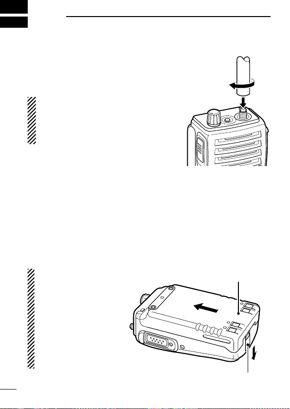
1 ACCESSORIES ........................................................................... 1–2
Accessory attachments ................................................................ 1
2 PANEL DESCRIPTION .............................................................. 3–11
Front, top and side panels ............................................................ 3
Function display............................................................................ 6
Programmable function keys ........................................................ 7
3 CONVENTIONAL OPERATION............................................... 12–18
Turning power ON....................................................................... 12
Channel selection ....................................................................... 12
Call procedure ............................................................................ 13
Receiving and transmitting ......................................................... 14
Scrambler function...................................................................... 17
User set mode ........................................................................... 18
4 BIIS OPERATION .................................................................... 19–34
Default setting............................................................................. 19
Receiving a call ..........................................................................20
Transmitting a call ....................................................................... 23
Receiving a message ................................................................. 26
Transmitting a status................................................................... 29
Transmitting an SDM .................................................................. 30
Position data transmission.......................................................... 31
Printer connection....................................................................... 32
PC connection ............................................................................ 32
BIIS ANI...................................................................................... 32
Auto emergency transmission .................................................... 33
Stun function............................................................................... 33
BIIS indication............................................................................. 34
Priority A channel selection ........................................................ 34

vi
TABLE OF CONTENTS
SUPPLIED ACCESSORIES
The following accessories are supplied: Qty.
•Flexibleantenna.........................................1
•Batterypack............................................1
•Jackcover .............................................1
•Beltclip................................................1
• Function name stickers* (KEY-STICKER) . . . . . . . . . . . . . . . . . . . . .1
*There are no names on the programmable function keys since the func-
tions can be freely assigned to [P0] to [P3], [Red], [ ] and [ ]
keys.
Attach the supplied function name stickers above the appropriate keys
for easy recognition of that key’s assigned function.
Versions of the IC-F50/F60 which display the “FM AP-
PROVED” symbol as at left on the serial number seal, con-
form to intrinsically safe ratings of the FMRC (Factory Mutual
Research Corporation).
Intrinsically safe : Class I, II, III, Division 1, Groups C, D, E, F, G
Nonincendive : Class I, Division 2, Groups A, B, C, D
Connected battery pack : BP-227FM
The repair and maintenance of an FM approved transceiver can only be per-
formed in an Factory Mutual approved repair facility. The FM approval will be
canceled if FM intrinsically safe radios are repaired anywhere else except in an
approved facility.
5 BATTERY CHARGING ............................................................ 35–44
Battery charging ......................................................................... 35
Caution ....................................................................................... 36
Optional battery chargers ........................................................... 37
Optional battery case.................................................................. 43
6 SPEAKER-MICROPHONE ...................................................... 45–46
Optional HM-169/170GP description.......................................... 45
Attachment ................................................................................. 46
7 OPTIONS ................................................................................. 47–48

1
1ACCESSORIES
Accessory attachments
DFlexible antenna
Connect the supplied flexible antenna
to the antenna connector.
CAUTION:
•
NEVER HOLD the antenna when
carrying the transceiver.
•
Transmitting without an antenna
may damage the transceiver.
DBattery pack
To attach the battery pack:
Slide the battery pack on the back of the transceiver in the direction
of the arrow (q), then lock it with the battery release button.
• Slide the battery pack until the battery release button makes a ‘click’
sound.
To release the battery pack:
Push the battery release button in the direction of the arrow (w) as
shown below. The battery pack is then released.
NEVER release or at-
tach the battery pack
when the transceiver
is wet or soiled. This
may result water or
dust getting into the
transceiver/battery
pack and may result in
the transceiver being
damaged.
q
w
Battery pack
Battery release button

DJack cover
Attach the jack cover when the optional speaker-microphone is not
used.
To attach the jack cover:
qInsert the jack cover into the
[SP MIC] connector.
wTighten the screw.
To detach the jack cover:
eUnscrew the screw with a
phillips screwdriver.
rDetach the jack cover for the
speaker-microphone con-
nection.
q
w
e
r
DBelt clip
Attach the belt clip to the back of the transceiver with the supplied
screws.
Supplied screws
2
1
ACCESSORIES
1

3
2PANEL DESCRIPTION
Front, top and side panels
q
i
u
w
e
r
t
y
Microphone
Function display
(p. 6)
Speaker
(See the following
NOTE.)
NOTE: If the speaker netting (for dust proofing) becomes wet,
dry it with a hair drier (cool mode) etc. before operating the
transceiver. Otherwise the audio may be difficult to hear for loss
of the sound pressure.

4
2
PANEL DESCRIPTION
2
qVOLUME CONTROL [VOL]
Turns power ON and adjusts the audio level.
wRED BUTTON
The desired function can be assigned by your dealer.
eANTENNA CONNECTOR
Connects the supplied antenna.
rSPEAKER-MICROPHONE CONNECTOR [SP MIC]
Connects the optional speaker-microphone. (p. 46)
[SP MIC] jack cover
NOTE: KEEP the [SP MIC]
jack cover attached to the
transceiver when the speaker-
microphone is not used.
(See p. 2 for details)
tDEALER-PROGRAMMABLE KEYS [P0] to [P3]
The desired functions can be assigned independently by your
dealer.
yCH UP AND DOWN KEYS [ ]/[ ]
During standby condition, push to select an operating channel.
After pushing [TX Code CH Select], push to select a TX code
channel.
After pushing [DTMF Autodial], push to select a DTMF channel.
After pushing and holding [Scan A Start/Stop]/[Scan B Start/
Stop], push to select a scan group.
After pushing [Digital], push to select a BIIS code, status
number or SDM.
*Desired functions can be assigned independently by your dealer.
Continue to the next page.

5
2PANEL DESCRIPTION
uTRANSMIT/BUSY INDICATOR
Lights red while transmitting; lights green while receiving a sig-
nal, or when the squelch is open.
iPTT SWITCH [PTT]
Push and hold to transmit; release to receive.

6
2
PANEL DESCRIPTION
2
Function display
ru
y
i
t
e
w
q
qOUTPUT POWER INDICATOR
Appears when Low 2 or Low 1 is selected.
wAUDIBLE INDICATOR
Appears when the channel is in the ‘audible’ (unmute) condi-
tion.
Appears when the specified 2/5-tone/BIIS code is received.
eCOMPANDER INDICATOR
Appears when the compander function is activated.
rKEY LOCK INDICATOR
Appears during the key lock function ON.
tSCRAMBLER INDICATOR
Appears when the voice scrambler function is activated.
yBELL INDICATOR
Appears/blinks when the specific 2/5-tone/BIIS code is re-
ceived, according to the programming.
uBATTERY INDICATOR
Appears or blinks when the battery power decreases to a speci-
fied level.
iALPHANUMERIC DISPLAY
Displays the operating channel number, channel names, Set
mode contents, DTMF numbers, etc.

7
2PANEL DESCRIPTION
Programmable function keys
The following functions can be assigned to [P0], [P1], [P2], [P3],
[Red], [ ] and [ ] programmable function keys.
Consult your Icom dealer or system operator for details concern-
ing your transceivers programming.
If the programmable function names are bracketed in the following
explanations, the specific switch used to activate the function de-
pends on programming.
CH UP AND DOWN KEYS
• Select an operating channel.
• Select a transmit code channel after pushing the [TX Code CH
Select] keys.
• Select a DTMF channel after pushing the [DTMF Autodial] key.
• Select a scan group after pushing and holding the [Scan A Start/
Stop]/[Scan B Start/Stop] keys.
• Select a BIIS code, status number or SDM after pushing the
[Digital] key.
BANK SELECT KEY
Push this key, then push [CH Up] or [CH Down] to select the de-
sired bank.
SCAN START/STOP KEYS
Push this key to start scanning; and push again to stop.
Push and hold this key to indicate the scan group, then select
the desired scan group using [CH Up]/[CH Down].
SCAN TAG KEY
Adds or deletes the selected channel to the scan group.

8
2
PANEL DESCRIPTION
2
PRIORITY CHANNEL KEYS
Push to select Priority A or Priority B channel.
Push and hold [Prio A (Rewrite)] to rewrite the Prio A channel.
MR-CH 1/2/3/4 KEYS
Select an operating channel directly.
MONITOR KEY
Mute and release the CTCSS (DTCS) or 2-tone squelch mute.
Open any squelch/deactivate any mute while pushing this key.
(LMR operation only)
Activates one of (or two of) the following functions on each
channel independently: (PMR or BIIS PMR operation only)
• Push and hold to un-mute the channel (audio is emitted; ‘Audible’
condition).
• Push to mute the channel (sets to ‘Inaudible’ only).
• Push to un-mute the channel (sets to ‘Audible’ only).
• Push after the communication is finished to send a ‘reset code’.
NOTE: The un-mute condition (‘Audible’ condition) may auto-
matically return to the mute condition (‘Inaudible‘ condition)
after a specified period.
LOCK KEY
Push and hold to electronically lock all programmable keys except
the following:
[Call] (incl. Call A and Call B), [Moni(Audi)] and [Emergency] keys.
OUTPUT POWER SELECTION KEY
Select the transmit output power temporarily or permanently, de-
pending on the pre-setting.
• Ask your dealer for the output power level for each selection.

9
2PANEL DESCRIPTION
C.TONE CHANNEL ENTER KEY
Select the continuous tone channel using [CH Up]/[CH Down]
keys to change the tone frequency/code setting after pushing this
key for permanent operation.
TALK AROUND KEY
Turn the talk around function ON and OFF.
• The talk around function equalizes the transmit frequency to the re-
ceive frequency for transceiver-to-transceiver communication.
WIDE/NARROW KEY
Push to toggle the IF bandwidth between wide and narrow.
• The wide passband width can be selected from 25.0 or 20.0 kHz
using the CS-F50 cloning software. (PMR or BIIS PMR operation
only) Ask your dealer for details.
DTMF AUTODIAL KEY
Push to enter the DTMF channel selection mode. Then select
the desired DTMF channel using [CH Up]/[CH Down] keys.
After selecting the desired DTMF channel, push this key to
transmit the DTMF code.
DTMF RE-DIAL KEY
Push to transmit the last-transmitted DTMF code.
CALL KEYS
Push to transmit a 2/5-tone/BIIS ID code.
• Call transmission is necessary before you call another station de-
pending on your signalling system.
• The [Call A] and/or [Call B] keys may be available when your system
employs selective ‘Individual/Group’ calls. Ask your dealer which call
is assigned to each key.

10
2
PANEL DESCRIPTION
2
EMERGENCY KEYS
Push and hold to transmit an emergency call.
When [Emergency Single (Silent)] or [Emergency Repeat (Si-
lent)] is pushed, an emergency call is transmitted without a
beep emission and LCD indication change.
• If you want to cancel the emergency call, push (or push and hold)
the key again before transmitting the call.
• The emergency call is transmitted one time only or repeatedly
until receiving a control code depending on the pre-setting.
TX CODE ENTER KEY (PMR or BIIS PMR operation only)
Push to enter the direct ID code edit mode, for both 5-tone
and MSK. Then set the desired digit using [CH Up]/[CH Down]/
[TX Code CH Up]/[TX Code CH Down]. (p. 16)
TX CODE CHANNEL SELECT KEY
Push to enter the direct ID code channel selection mode. Then
set the desired channel using [CH Up]/[CH Down]/[TX Code CH
Up]/[TX Code CH Down]. (p. 15)
While in ID code channel selection mode, push for 1 sec. to
enter the ID code edit mode for 5-tone and MSK. Then set the
desired digit using [CH Up]/[CH Down]/[TX Code CH Up]/[TX
Code CH Down]. (p. 16)
TX CODE CHANNEL UP/DOWN KEYS
Push to select a TX code channel directly.
ID MEMORY READ KEY (PMR or BIIS PMR operation only)
Recalls detected ID codes.
• Push this key, then push [CH Up]/[CH Down] for selection.
• Up to 5 ID’s are memorized.
Push and hold to erase the selected memorized ID’s.

11
2PANEL DESCRIPTION
VOICE SCRAMBLER FUNCTION
Push to toggle the voice scrambler function ON and OFF.
COMPANDER KEY
Push to toggle the compander function ON and OFF.
The compander function reduces noise components from the
transmitting audio to provide clear communication.
USER SET MODE KEY
Push and hold to enter user set mode.
• During user set mode, push this key to select an item, and push
[CH Up]/[CH Down] to change the value or condition.
Push and hold this key again to exit user set mode.
• User set mode is also available via the ‘Power ON function’.
Please refer to p. 18 also.
DIGITAL KEY (BIIS operation only)
Push to select the call ID list, transmit message and standby
condition. Toggles between queue channel and received mes-
sage record indication after queue channel is selected.
Push and hold to select queue channel indication.
STATUS UP/DOWN KEYS (BIIS operation only)
While in the standby condition, push to display the transmit sta-
tus indication and select a status number.
When a received SDM is displayed, push to cancel the auto-
matic scroll and scroll the message manually.
When an SDM that contains more than 8 characters is dis-
played, push to scroll the message manually.

12
3
CONVENTIONAL OPERATION
2
3
Turning power ON
qRotate [VOL] to turn power ON.
wIf the transceiver is programmed for a start up passcode, input
digit codes as directed by your dealer.
• The keys in the table below can be used for password input:
• The transceiver detects numbers in the same block as identical.
Therefore “01234” and “56789” are the same.
KEY
NUMBER 0
5
4
9
3
8
2
7
1
6
eWhen the “PASSWORD” indication does not clear after input-
ting 4 digits, the input code number may be incorrect. Turn the
power off and start over in this case.
Channel selection
Several types of channel selections are available. Methods may
differ according to your system set up.
NON-BANK TYPE:
Push [ ]/[ ] to select the desired operating channel, in se-
quence; or, push one of the [MR-CH 1] to [MR-CH 4] keys to se-
lect a channel directly.
BANK-TYPE:
Push [Bank], then push [ ] or [ ] to select the desired bank.
AUTOMATIC SCAN TYPE:
Channel setting is not necessary for this type. When turning the
power ON, the transceiver automatically starts scanning. Scanning
stops when receiving a call.

13
3CONVENTIONAL OPERATION
Call procedure
When your system employs tone signalling (excluding CTCSS and
DTCS), the call procedure may be necessary prior to voice trans-
mission. The tone signalling employed may be a selective calling
system which allows you to call specific station(s) only and prevent
unwanted stations from contacting you.
qSelect the desired TX code channel or 2/5-tone code according
to your System Operator’s instructions.
• This may not be necessary depending on programming.
• Refer to pgs. 15, 16 for selection.
wPush the call switch (assigned to one of the dealer programma-
ble switches: [P0], [P1], [P2], [P3], [Red], [ ] and [ ]).
eAfter transmitting a 2/5-tone code, the remainder of your com-
munication can be carried out in the normal fashion.
Selective calling Non-selective calling
Other manuals for UHF IC-F60
1
This manual suits for next models
1
Table of contents
Other Icom Transceiver manuals