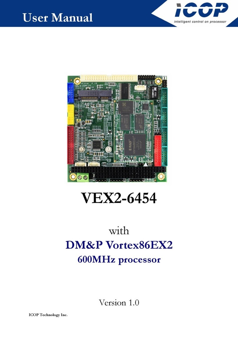
Icop VEX2-6415 User manual

ICOP Technology Inc.
User Manual
VEX2-6415
with
DM&P Vortex86EX2
600MHz processor
Version 1.0

VEX2-6415 User Manual
ICOP Technology Inc. I
Copyright
The information in this manual is subject to change without notice for
continues improvement in the product. All rights are reserved. The manufacturer
assumes no reasonability for any inaccuracies that may be contained in this
document and makes no commitment to update or to keep current the
information contained in this manual.
No part of this manual may be reproduced, copied, translated or transmitted,
in whole or in part, in any form or by any means without the prior to written
permission of ICOP Technology Inc.
Copyright ⓒ 2019 ICOP Technology Inc
Trademarks Acknowledgement
Vortex86EX2TM is the registered trademark of DM&P Electronics Inc.
Other brand names and product names that appear in this document are the
properties and registered trademarks of their respective owners. All names
mentioned herewith are served for identification purpose only.

VEX2-6415 User Manual
ICOP Technology Inc. II
Revision History
Revision Date Remark
1.0 First version release

VEX2-6415 User Manual
ICOP Technology Inc. III
Table of Contents
Copyright ...................................................................................................................... I
Trademarks Acknowledgement ................................................................................ I
Revision History ......................................................................................................... II
Table of Contents ..................................................................................................... III
1 General Information ........................................................................................... 1
1.1 Overview .................................................................................................................................... 1
1.2 Block diagram ............................................................................................................................. 3
1.3 Specifications .............................................................................................................................. 4
1.4 Ordering Information ................................................................................................................. 5
Optional Accessary .......................................................................................................................... 5
2 Hardware Information ....................................................................................... 6
2.1 Dimension .................................................................................................................................. 6
2.2 Board Outline ............................................................................................................................. 7
2.3 Connector Location .................................................................................................................... 8
2.4 Connector and Jumper Summary ................................................................................................ 9
2.5 Pin Assignments & Jumper Settings .......................................................................................... 10
J3: KBD ......................................................................................................................................... 10
J4: Mouse ....................................................................................................................................... 10
J5: Reset ......................................................................................................................................... 10
J6: PRINT ...................................................................................................................................... 11
J7: GPIO ........................................................................................................................................ 11
J8: USB .......................................................................................................................................... 12
J9: LAN1 ....................................................................................................................................... 12
J10: LAN2 ...................................................................................................................................... 12

VEX2-6415 User Manual
ICOP Technology Inc. IV
J11: Mini PCIe1 .............................................................................................................................. 13
J13: Mini PCIe2 .............................................................................................................................. 14
J14: COM1 RS232/485 (TTL Option) ........................................................................................... 15
J15: RS485 from COM2 ................................................................................................................. 15
J16: COM2 RS232/485 (TTL Option) ........................................................................................... 15
J17: COM3 RS232 (TTL Option) ................................................................................................... 15
J18: COM4 RS232 (TTL Option) ................................................................................................... 16
J19: Power Connector .................................................................................................................... 16
JP1: Console_EN ........................................................................................................................... 16
JP3: USB ........................................................................................................................................ 16
JP4: RS232/485 Jumper Switch for COM1 .................................................................................... 16
JP5: RS232/485 Jumper Switch for COM2 .................................................................................... 17
2.6 System Mapping ........................................................................................................................ 18
3 Software Resources ........................................................................................... 21
3.1 ICOP Technical Resource Website.......................................................................................... 21
Technical support ...................................................................................................... 22
Warranty ...................................................................................................................... 23

VEX2-6415 User Manual
ICOP Technology Inc. 1
1 General Information
1.1
Overview
The Vortex86EX2 series is the new generation heterogeneous two-core CPU
which utilizes the Master and Slave cores to simultaneously run two different
BIOSs & Operating Systems without affecting each other; equipped with various
programmable I/O; it's designed for real-time desired industrial/automation
applications.
Perfect Replacement Solution for Vortex86DX Platform.
1. CPU instruction upgrade
2. DRAM from DDR2 to DDR3
3. Manufacturing process from 90nm to 65nm

VEX2-6415 User Manual
ICOP Technology Inc. 2
VEX2-6415 is a solution of tiny based on VEX2-DIP168 CPU module, which
has lower power consumption and multiple I/O selections.
Features of VEX2-6415:
Vortex86EX2 Processor 600MHz
512MB/1GB DDR3 Onboard
4S/3U/4/2LAN/16GPIO/2MiniPCIe
Onboard eMMC / MicroSD socket
Operation Temperature: -20°C ~ +70°C / -40°C ~ +85°C (Optional)

VEX2-6415 User Manual
ICOP Technology Inc. 3
1.2
Block diagram
Vortex86EX2 DIP-168 Vortex86EX2-PCB Bottom View
Vortex86EX2-DIP168

VEX2-6415 User Manual
ICOP Technology Inc. 4
1.3
Specifications
Processor DM&P Vortex86EX2 Processor 600MHz
RAM 512MB/1GB DDR3 Onboard
IOS Core boot BIOS
Expansion Mini PCIe x2
LAN Integrated 10/100Mbps Ethernet x2
Disk Support Micro SD
Micro SD Card/eMMC
I/O Interface
COM x 4 (2 x RS232/485)
16-bit GPIO x 1
USB (Version. 2.0) x 3 (Option x1)
Connectors
2.54mm 5-pin pin header for Mouse x 1
2.54mm 5-pin box header for Keyboard x 1
2.00mm 20-pin box header for GPIO x 1
2.00mm 2-pin pin header for Reset x 1
2.00mm 10-pin box header for USB x 1
2.00mm 2-pin pin header for Console jumper x 1
2.00mm 8-pin pin header for LAN x 1
2.00mm 10-pin box header for COM x 4
2.00mm 4-pin pin header for USB x 1 (Option)
2-pin header for Power connector x 1
2.00mm 20-pin box header for Print x 1
RJ45 connector x 1
SIM Card slot x 1
Micro SD slot x1
Power Requirement 5VDC @ 480mA
Weight 75g
Dimensions 100 x 66mm (3.94 x 2.6 inches)
Operating Temp. -20°C to +70°C
-40°C to +85°C (Option)
Operating System
Support
Windows Embedded Compact 7
Windows Embedded CE6.0
DOS
QNX
Linux
FreeBSD

VEX2-6415 User Manual
ICOP Technology Inc. 5
1.4
Ordering Information
PART NO.
VEX2-6415-4C4NE VEX2-6415-4C3NE VEX2-6415-4C4EE
CPU Speed
600MHz 600MHz 600MHz
DRAM
(DDR3) 1GB 512MB 1GB
Disk
Support Micro SD x2 Micro SD x2 Micro SD Card
4GB eMMC
LAN 2 2 2
COM 4 4 4
USB (v2.0)
3 (Option x1) 3 (Option x1) 3 (Option x1)
GPIO 16-bit 16-bit 16-bit
Parallel 1 1 1
PS/2 2 2 2
Mini PCIe
2 2 2
Optional Accessary
CABLE-SET-6415-4C Cable set for VEX2-6415-4C (RS232 x4, USB, PRINT, GPIO, LAN,
VGA, PS2KB x2)

VEX2-6415 User Manual
ICOP Technology Inc. 6
2 Hardware Information
2.1
Dimension

VEX2-6415 User Manual
ICOP Technology Inc. 7
2.2
Board Outline

VEX2-6415 User Manual
ICOP Technology Inc. 8
2.3
Connector Location

VEX2-6415 User Manual
ICOP Technology Inc. 9
2.4
Connector and Jumper Summary
Nbr. Name Type of Connections Nbr of Pin
J2 Micro SD Micro SD slot
J3 KBD Wafer, 2.5mm, 5x1 5
J4 Mouse Wafer, 2.5mm, 5x1 5
J5 Reset Pin Header, 2.0mm, 2x1 2
J6 PRINT Box Header, 2.0mm, 13x2 25
J7 GPIO Box Header, 2.0mm, 10x2 20
J8 USB Box Header, 2.0mm, 5x2 10
J9 LAN1 RJ45 connector
J10 LAN2 Pin Header, 2.0mm, 4x2 8
J11 Mini PCIe1 Standard Mini PCI Express connector 52
J12 SIM card holder Micro SIM socket
J13 Mini PCIe2 Standard Mini PCI Express connector 52
J14 COM1 RS232/485 (TTL Option)
Box Header, 2.0mm, 5x2 10
J15 RS485 from COM2 Molex, 2.54mm, 3x1 3
J16 COM2 RS232/485 (TTL Option)
Box Header, 2.0mm, 5x2 10
J17 COM3 RS232 (TTL Option) Box Header, 2.0mm, 5x2 10
J18 COM4 RS232 (TTL Option) Box Header, 2.0mm, 5x2 10
J19 Power Connector Pin Header, 5.0mm, 2x1 2
JP1 Console_EN Pin Header, 2.0mm, 2x1 2
JP3 USB (Opiton) Pin Header, 2.0mm, 4x1 4
JP4 RS232/485 Jumper Switch for
COM1
Header 2, 2x1 2
JP5 RS232/485 Jumper Switch for
COM2
Header 2, 2x1 2

VEX2-6415 User Manual
ICOP Technology Inc. 10
2.5
Pin Assignments & Jumper Settings
J3: KBD
Pin#
Single Name
1. KBCLK
2 KBDATA
3 -
4 GND
5 VCC
J4: Mouse
Pin#
Single Name
1. MSCLK
2 MSDATA
3 -
4 GND
5 VCC
J5: Reset
Pin#
Single Name
1. RESET-
2 GND

VEX2-6415 User Manual
ICOP Technology Inc. 11
J6: PRINT
Pin#
Single Name
Pin #
Single Name
1. STB- 2 PD0
3 PD1 4 PD2
5 PD3 6 PD4
7 PD5 8 PD6
9 PD7 10 PACK-
11 BUSY 12 PE
13 SLCT 14 AFD-
15 ERR- 16 INIT-
17 SLIN- 18 GND
19 GND 20 GND
21 GND 22 GND
23 GND 24 GND
25 GND
J7: GPIO
Pin#
Single Name
Pin #
Single Name
1. GND 2 VCC3 (+3.3V)
3 GPIO00 4 GPIO10
5 GPIO01 6 GPIO11
7 GPIO02 8 GPIO12
9 GPIO03 10 GPIO13
11 GPIO04 12 GPIO14
13 GPIO05 14 GPIO15
15 GPIO06 16 GPIO15
17 GPIO07 18 GPIO16
19 VCC3(+3.3V)
20 GND

VEX2-6415 User Manual
ICOP Technology Inc. 12
J8: USB
Pin#
Single Name
Pin #
Single Name
1. VCC 2 VCC
3 LUSBD1- 4 LGUSBD1-
5 LUSBD1+ 6 LGUSBD1+
7 GND 8 GND
9 GND 10 GND
J9: LAN1
Pin#
Single Name Pin #
Single Name
1. GND 2 GND
3 RX- 4 GND
5 GND 6 RX+
7 TX- 8 TX+
L2 LINK/ACTIVE
H1 FGND
L3 DUPLEX H2 FGND
J10: LAN2
Pin#
Single Name
Pin #
Single Name
1. TX+ 2 TX-
3 RX+ 4 Duplex
5 LED1+ 6 RX-
7 LED0+ 8 Link/Active

VEX2-6415 User Manual
ICOP Technology Inc. 13
J11: Mini PCIe1
Pin#
Single Name
Pin #
Single Name
1. WAKE# 2 VCC3(+3.3V)
3 - 4 GND
5 - 6 -
7 - 8 SIM-VCC
9 GND 10 SIM-IO
11 PE0_CLK- 12 SIM-CLK
13 PE0_CLK+ 14 SIM-RST
15 GND 16 SIM-VPP
17 - 18 GND
19 - 20 -
21 GND 22 PE0_RST
23 PE0_RX- 24 VCC(+3.3V)
25 PE0_RX+ 26 GND
27 GND 28 -
29 GND 30 -
31 PE0_TX- 32 -
33 PE0_TX+ 34 GND
35 GND 36 PE0_USB-
37 GND 38 PE0_USB+
39 VCC3(+3.3V)
40 GND
41 VCC3(+3.3V)
42 LED_WWAN#
43 GND 44 -
45 - 46 -
47 - 48 -
49 - 50 GND
51 - 52 VCC3(+3.3V)

VEX2-6415 User Manual
ICOP Technology Inc. 14
J13: Mini PCIe2
Pin#
Single Name
Pin #
Single Name
1. WAKE2# 2 VCC3(+3.3V)
3 - 4 GND
5 - 6 -
7 - 8 -
9 GND 10 -
11 PE1_CLK- 12 -
13 PE1_CLK+ 14 -
15 GND 16 -
17 - 18 GND
19 - 20 -
21 GND 22 PE1_RST
23 PE1_RX- 24 VCC(+3.3V)
25 PE1_RX+ 26 GND
27 GND 28 -
29 GND 30 -
31 PE1_TX- 32 -
33 PE1_TX+ 34 GND
35 GND 36 PE1_USB-
37 GND 38 PE1_USB+
39 VCC3(+3.3V)
40 GND
41 VCC3(+3.3V)
42 LED_WWAN#
43 GND 44 -
45 - 46 -
47 - 48 -
49 - 50 GND
51 - 52 VCC3(+3.3V)

VEX2-6415 User Manual
ICOP Technology Inc. 15
J14: COM1 RS232/485 (TTL Option)
Pin#
Single Name Pin #
Single Name
1. DCD1/1RS485-
2 RXD1/1RS485+
3 TXD1 4 DTR1
5 GND 6 DSR1
7 RTS1 8 CTS1
9 RI1 10 NC
J15: RS485 from COM2
Pin#
Single Name
1 2RS485+
2 2RS485-
3 GND
J16: COM2 RS232/485 (TTL Option)
Pin#
Single Name Pin #
Single Name
1. DCD2/2RS485-
2 RXD2/2RS485+
3 TXD2 4 DTR2
5 GND 6 DSR2
7 RTS2 8 CTS2
9 RI2 10 NC
J17: COM3 RS232 (TTL Option)
Pin#
Single Name
Pin #
Single Name
1. DCD3 2 RXD3
3 TXD3 4 DTR3
5 GND 6 DSR3
7 RTS3 8 CTS3
9 RI3 10 NC
Table of contents
Other Icop Computer Hardware manuals

Icop
Icop VSX-6116-V2 User manual

Icop
Icop QEC-M-070T User manual

Icop
Icop QEC-M-090T User manual

Icop
Icop VDX-6328RD User manual

Icop
Icop IBW-6954 User manual

Icop
Icop VEX-SOM User manual

Icop
Icop VSX-6115-V2 User manual

Icop
Icop VSX-6154 User manual

Icop
Icop VSX-6114-V2 User manual

Icop
Icop QEC-M-01 User manual