manuals.online logo
Brands
  1. Home
  2. •
  3. Brands
  4. •
  5. Ideal-Standard
  6. •
  7. Plumbing Product
  8. •
  9. Ideal-Standard CERAMIX A 1100 Series User manual

Ideal-Standard CERAMIX A 1100 Series User manual

max. 150
350 30 - 50
Ø 63
G1 1/4
123 63
max. 25
130
SW 13
max. 150
350 30 - 50
Ø63
G1 1/4
138 76
max. 25
143
SW 13
16
12
3
4
5
6
7
8
910
11
12
13
14
15
17
18
19
20
21
22
SW 2,5
SW 2,5
1a
2
3
13a
23
beigepackt
enclosed
ci-annexé
accluso
8Ersatzteil - Regelung / Ordering spares / Pièces de rechange
Parti di ricambio 9Auswechseln der Kartusche / Changing the cartridge / Remplacement de
la cartouche / Cambio della cartuccia
A 960 754 XX
A 961 317 XX
A 963 825 NU (3x)
A 960 463 NU
DE=
A 961 101 NU
A 961 868 NU
A 963 361 NU
A 961 172 NU
DE = Version für Durchlauferhitzer
DE = Version for flow-heaters
DE = Version pour chauffe-eaux instantanés
DE = Versione per scaldabagno instantaneo
A 960 321 XX
DE= A 960 932 XX
A961230XX
A 963 282 XX
Kunststoff-Überziehrohr
A 963 345 NU (M8)
A 963 305 NU
A 961 063 XX
A 960 699 XX
A 963 309 NU
A 963 054 NU
A 963 334 NU
A 961 155 NU
A 961 338 NU
A 963 334 NU
A 963 054 NU
A 963 309 NU
SW 2,5
1
2
3
4
5
6
7
8
9
AA
Detail X
■Eckventile absperren. Stopfen 3 heraushebeln.
Schraube 2 lösen. Griff 1 nach oben abziehen. Klam-
mern von Kappenhalter 6 zusammendrücken und
Kappe 4 abziehen. Stellring 7 wechselweise ab-
hebeln (siehe Detail X). Schrauben 5 lösen. Kartu-
sche 6 mit Kappenhalter abnehmen. Auflagefläche
der Dichtringe 9 im Batteriekörper säubern.
Neue Kartusche mit Kappenhalter 6 einsetzen.
Schrauben 5 wechselweise und nicht zu fest anzie-
hen. Stellring 7 justieren und aufdrücken ( siehe
Abschnitt 7 "Temperaturbegrenzer". Teile 1 - 4 wie-
der montieren. Funktion und Dichtigkeit überprüfen.
■Shut off the angle valves. Lever out stopper 3 and
undo screw 2. Remove handle 1 by pulling upwards.
Press together the clips of cap holder 6 and pull off
cap 4. Remove adjustment ring 7 by levering off from
alternate sides ( see Detail X ). Undo screws 5.
Remove cartridge 8 with cap holder 6. Clean the
surfaceonwhichsealing rings9 restin thebody ofthe
mixer unit.
Fit new cartridge with cap holder 6. Tighten screws 5
alternately and not too tight. Position the adjustment
ring 7 and press it onto the unit ( see Chapter 7
" Temperature Limiter " ). Refit parts 1 - 4.
Check that the unit functions correctly and does not
leak.
■Bloquer les soupapes d'équerre. Faire ressortir le
bouton 3 et desserrer la vis 2. Retirer le levier 1 en
tirant vers le haut. Appuyer pour les rapprocher sur
les brides de l'anneau de fixation du capuchon 6 et
retirer le capuchon 4. Soulever la bague d'arrêt 7 à
plusieurs endroits avec un tournevis ( voir détail X )
et dévisser les vis 5. Retirer la cartouche 8 avec
l'anneau de fixation du capuchon. Nettoyer la surface
d'appui des joints 9 àl'intérieur du corps du robinet
mélangeur.
Placer une nouvelle cartouche avec un anneau de
fixation pour le capuchon 6 et serrer alternativement,
pas trop fort, les vis 5. Ajuster la bague d'arrêt 7 et
l'enfoncer ( voir description point 7 " Limitateur de
température " ). Remonter les pièces 1 à4 et vérifier
le bon fonctionnement et l'étanchéité.
■Chiuderei rubinetti sottolavabo.Togliere ilcoprivite
3. Svitare la vite 2. Sfilare la leva di comando 1
tirandola verso l'alto. Premere l'una contro l'altra le
due molle dell'anello portacappuccio 6 e sfilare il cap-
puccio 4. Con l'aiuto di un cacciavite a lama piatta
fare leva alternativamente ai due lati dell'anello di
regolazione 7 per toglierlo ( particolare X ).
Svitare le tre viti 5 e togliere la cartuccia 6 insieme
all'anello portacappuccio. Puliere la superficie
d'appoggiodelleguarnizioni9 nel corpodelmiscelatore.
Inserire la nuova cartuccia con relativo anello porta-
cappuccio 6. Avvitare le viti 5 in alternanza senza
stringerle troppo. Girare l'anello di regolazione 7 nella
posizione desiderata e montarlo esercitando una leg-
gera pressione ( vedi descrizione " Limitatore di
temperatura acqua calda " ). Rimontare quindi le parti
da 1 a 4. Verificare infine il regolare funzionamento e
la tenuta dei componenti.
ist dem Öko-set beigepackt
Montage- und Bedienungsanleitung
Installation Instructions
Instructions de montage
Istruzioni di montaggio
Dem Benutzer der Armatur aushändigen.
Please hand over to the user of the fitting.
S.V.P., remettre àl'utilisateur de la robinetterie.
Si prega di voler consegnare le presenti
istruzioni all'utilizzatore della rubinetteria.
Typ / Type / Tipo
A 1100 .., A 1101.., A 1102.., A 1272..
Aquariane plus
Mitigeur monocommande pour lavabo
Waschtisch-Einhebel-Mischbatterie
Single lever basin mixer
Miscelatore monocomando per lavabo
CERAMIX No. 1
TDA 730 / 1000 / 965 322
Made in Germany
Ihr Installateur / Your plumber / Votre installateur / L'installatore
■ Bestellnummern für Ersatzteile siehe Zeichnung
auf dieser Seite. Bei Bestellung der Teile für XX die
Oberflächen-Kennung einsetzen (z.B: bei chrom statt
XX = AA einsetzen).
Oberflächen-Kennung siehe Ersatzteilbuch.
■Les numéros de commande des pièces de
rechange sont indiqués dans le schéma. Pour
commander des pièces inscrire les suffixes
correspondants (par example: pour chrome indiquer
les suffixes AA au lieu de XX).
Les suffixes sont indiqués dans le catalogue des
piéces de rechange.
■I codici di ordinazione dei ricambi sono riportati sul
disegno a lato. Per l'ordinazione di ricambi indicare il
relativo suffisso codice (per esempio: per cromato
indicare AA invece di XX). I suffissi codici sono riportati
nel catalogo ricambi.
■ Spare part numbers are shown in diagram on this
page. When ordering parts add the appropriate suffix.
(for example: for chrome use AA instead of XX)
See Spare part catalogue for suffixes.
A 1100 ..
A 1272 ..
Hersteller:
Ideal Standard
Pro-Service
Am Probsthof 15
53121 Bonn
Tel.: 0228-521580
Fax: 0228-521589
III
IV V
VI
I
II
Vor Beginn der Montage bitte sorgfältig durchlesen.
Please read these instructions carefully before commencing installation.
Prière de lire attentivement cette notice avant de procéder àl'installation.
Prima di iniziare il montaggio leggare attentamente le seguenti istruzioni.
1
Montage nur durch Fachmann.
Installation only by an expert.
Ne confier le montage qu'àun personnel spécialisé.
Far eseguire i lavori solo da un installatore.
2
max: 1 MPa ( 10 bar / 145 psi )
opt. : 0,1 MPa- 0,5 MPa (1 - 5 bar / 14,5-72,5 psi )
min: 0,1 MPa ( 1 bar / 14,5 psi )
> 0,5 MPa ( 5 bar / 72,5 psi ) ➜
dauerplastischer Kitt
permanently elastic putty
joint silicone
mastice plastico
plastische kit
kalt
cold
froid
fredda
koud
warm
hot
chaud
calda
auf
on
ouverture
aprire
omhoog
zu
off
fermeture
chiudere
omlaag
Bedienung / Operation / Utilisation / Istruzioni sull'uso
4
3Technische Daten / Technical data
Caractéristiques techniques / Dati tecnici
Prüfdruck:
Test pressure:
Pression d'essai:
Pressione massima di prova:
Testdruk:
1,6 MPa ( 16 bar / 232 psi ) max.
Betriebstemperatur:
Temperature:
Température
d'utilisation:
Temperatura
d'esercizio:
werktemperatuur:
90 C max.
Durchflußleistung:
Flow rate:
Débit:
Portata:
Doorstroomvermogen:
0,3 MPa ( 3 bar / 43,5 psi )
= 13 l/min
■Risciacquare accuratamente tutte le
condutture di alimentazione per eliminare ogni
residuo di sporco.Dopo aver curvato i tubi di
collegamento fare attenzione che l´asta di
comando dello scarico possa venir azionata
con facilità. Controllare la funzione e la tenuta
ermetica di tutti i collegamenti.
■Bien rincer les conduites d´arrivée d´eau,
pour enlever les restes de saleté. Après avoir
courbéles tuyaux, veiller àce que la tirette se
manoeuvre facilement. Contrôler le fonctionne-
ment et l'étanchéitéde tous les branchements.
■ Zulaufleitungen gut durchspülen, um
Schmutzreste zu entfernen. Nach dem Biegen
der Rohre darauf achten, daßsich die Zug-
stange leicht bewegen läßt. Funktion und Dich-
tigkeit überprüfen.
■Flush out supply pipes thoroughly to remove
traces of dirt. After bending the pipes, ensure
that the operating rod still moves freely. Check
that all the connections function correctly and
are leak-tight.
Warm
hot
chaud
calda
Kalt
cold
froid
fredda
koud
Warm
hot
chaud
calda
Kalt
cold
froid
fredda
koud
■ Zulaufschläuche werksseitig eingeschraubt und handfest
angezogen. Schläuche spannungsfrei ( nicht verdreht ) an-
schließen.
■ Supply hoses are screwed in and hand-tightened at the
factory. Connect up hoses free of tension ( not twisted )!
■ Tuyaux d'arrivée vissés et serrés àla main l'usine.Bran-
cher les tuyaux en évitant les tensions ( ne pas les tordre ).
■ Itubi dialimentazione sonoavvitati estretti amano in sede
di fabbricazione. Eseguire il collegamento in modo tale che i
tubi non siano sottoposti a sforzi di torsione o trazione!
5Pflege und Wartung / Maintenance / Entretien / Pulizia del miscelatore
■ Zur Reinigung der Armatur sollten nur seifenhal-
tige Reinigungsmittel verwendet werden.
Keinesfalls kratzende, scheuernde, alkohol-,
salzsäure-, phosphorsäure- oder essigsäurehaltige
Reinigungs- oder Desinfektionsmittel benutzen.
■Pour le nettoyage de la robinetterie, employer
seulement des produits contenant du savon. Jamais
denettoyants ou desdésinfectantsqui grattent, rayent,
contiennent de l'alcool ou de l'acide chlorhydrique ou
phosphorique.
■When cleaning the fitting, only use saponaceous
( i. e. soap - based ) agents. Never use abrasive or
scouring powders, cleaning agents containing alco-
hol, nitric acid or phosphoric acid, or desinfectants.
■Per la pulizia del miscelatore si consiglia di usare
solamente detergenti a base di sapone.
Non impiegare in nessun caso detergenti o disin-
fettanti abrasivi o contenenti alcool, acido cloridrico o
acido fosforico.
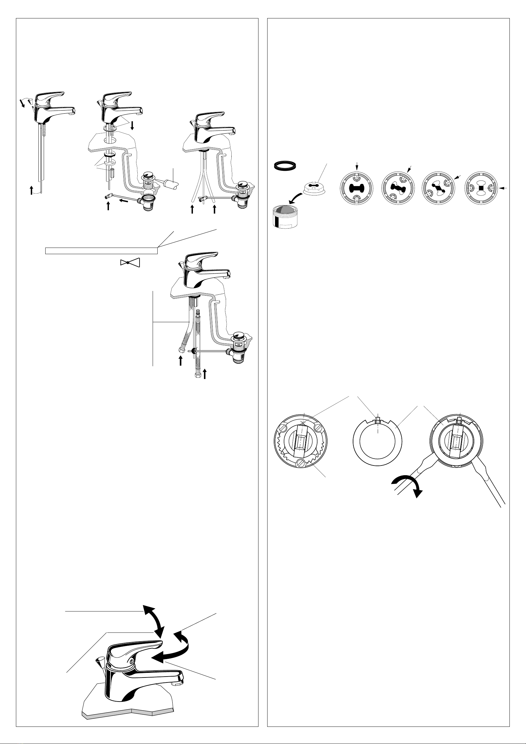
Dem Öko - Set ( siehe Plastic-Tüte ) ist eine grüne Wasserdrossel beigepackt.
Diese Wasserdrossel mit dieser Anleitung bitte an den Benutzer der Armatur
weitergeben.
6
ca.10 l/min
3 bar
ca. 8 l/min
3 bar
ca. 7 l/min
3 bar
ca. 6 l/min
3 bar
A 963 361 NU
■Einbau der Wasserdrossel
Nicht geeignet für Durchlauferhitzer ( DE )
und offene Heißwasserbereiter ( ND ).
Luftsprudler von der Armatur abschrauben. Wasser-
drossel wie im Bild dargestellt in den Luftsprudler
einsetzen. Gummiring über die Wasserdrossel legen
und den Luftsprudler wieder von Hand anschrauben.
■Montage de l'économiseur d'eau
Ne peut pas être utiliséavec des chauffe-
eau instantanés.
Dévisserl'aérateur durobinet. Retirerle joint.Installer
l'économiseur d'eau sur l'aérateur. Reposer le joint
sur l'économiseur. Revisser l'ensemble.
■Assembly of the flow restrictor
Not be used with instantaneous Water
Heaters and low pressure systems.
Unscrew the neoperl nozzle of the fitting. Insert the
flow restrictor into the neoperl nozzle as shown in the
picture. Put the rubber ring on top of the flow restrictor
and screw the neoperl nozzle by hand into the spout
of the fitting again.
■Montaggio del riduttore
Non per riscaldabagno instantaneo.
Smontare il neoperl. Montare il riduttore come
disegnato. Montare la guarnizione di sopra e fissare
il neoperl a máno.
Temperatur-Begrenzer - JUSTIERUNG ( Vermeidung von Verbrühungsgefahr )
Temperature Limiter - ADJUSTMENT ( protection against scalding )
Limitateur de température - AJUSTAGE ( Protection contre les brûlures )
7
B
7
■ Nachdem die Kartusche mit dem Rasterring fest-
geschraubt ist, Wasserzuführung öffnen.
Griffhebel aufstecken, Armatur öffnen und die ge-
wünschte Temperaturgrenze ansteuern.
In dieser Position Kartusche schließen und Griff-
hebel abziehen. Den Stellring 7 von oben so einset-
zen, daßdie Sperrnase ( A ) in etwa mittig hinter der
Griffhebelaufnahme einrastet ( siehe Bild II, Markie-
rung X ). Dabei darauf achten, daßdie Zähne des
Stellrings 7 in den Zahnkranz des Kappenhalters 6
greifen ( siehe Bild II, B ).
Kontrolle - den Griffhebel aufstecken, gegen den
Begrenzer drehen und Temperatur prüfen. Danach
Adapter, Kappe und Griffhebel wieder montieren.
NACHJUSTIERUNG
Mußder Stellring 7 neu positioniert werden, so ist
nach gleichem Schema zu verfahren.
Griffhebel gegen den Begrenzer drehen, Kartusche
schließen und Griffhebel lösen u. abziehen.
Mit einem Schraubendreher den Stellring 7 durch
wechselseitiges Abhebeln entfernen ( siehe Bild III ).
Neue Einstellung wie unter Justierung beschrieben
vornehmen.
■ After screwing tight the cartridge and locating ring,
turn on the water supply. Fit the lever-type handle,
turn on the mixer unit and move it to the desired
temperature limit.
In this position turn off the mixer unit and remove
the handle. Fit the adjustment ring 7 from above so
that the limit stop lug ( A ) engages approximately
centrally behind the handle mount ( see the X in Fig.
II ). Ensure that the teeth of the adjustment ring 7 grip
in the teeth on the inside rim of the cap holder 6 ( see
Fig. II, B ). Check: fit the lever-type handle, turn it as
far as the limiter and check the temperature. Then
refit adapter, cap and handle.
READJUSTMENT
If adjustment ring 7 has to be repositioned, follow the
same procedure.
Turn the handle as far as the limiter, turnoffthemixer
unit and unscrew and pull off the handle.
Remove the adjustment ring 7 by levering up from
alternate sides using a screwdriver ( see Fig. III ).
Readjust the temperature limiter as described in the
section " ADJUSTMENT ".
■Ouvrir l'arrivée d'eau après avoir assembléet vissé
la cartouche et la bague de blocage. Mettre le levier en
place, l'ouvrir jusqu'àla température limite désirée.
Unefoisarrivédans cette position,fermerlacartouche
et retirer le levier. Mettre la baguet d'arrêt 7 de par le
haut en sorte que le tenon de blocage ( A ) s'enclenche
àpeu près au centre, derrière le logement du levier (
voir Fig. II, repère X ). Veiller àce que les dents de la
bague d'arrêt 7 prennent dans la couronne dentée de
la bague de blocage ou de l'anneau de fixation du
capuchon 6 ( voir Fig. II, B ).
Contrôle. Mettre le levier en place, le tourner contre
le limitateur et vérifier la température.
Remonterensuite l'adaptateur,lecapuchon etle levier.
CORRECTION DU REGLAGE
S'il faut corriger la position de la bague d'arrêt 7,
procéder de façon analogue.
Tournerlelevier contrelelimitateur,fermer lacartouche
puis desserrer et retirer le levier.
Retirer la bague d'arrêt 7 àl'aide d'un tournevis en la
soulevant alternativement àplusieurs endroits ( voir
Fig. III ).
Faire le nouveau réglage comme décrit au paragraphe
Ajustage.
A
Bild II
Fig. II Bild III
Fig. III

This manual suits for next models

3

Other Ideal-Standard Plumbing Product manuals

Ideal-Standard Ceratherm T25 User manual

Ideal-Standard

Ideal-Standard Ceratherm T25 User manual

Ideal-Standard ULTRA FLAT NEW T449001 User manual

Ideal-Standard

Ideal-Standard ULTRA FLAT NEW T449001 User manual

Ideal-Standard W3718 Series User manual

Ideal-Standard

Ideal-Standard W3718 Series User manual

Ideal-Standard Contour 21 S3257 User manual

Ideal-Standard

Ideal-Standard Contour 21 S3257 User manual

Ideal-Standard Ceratherm C100 A7537AA User manual

Ideal-Standard

Ideal-Standard Ceratherm C100 A7537AA User manual

Ideal-Standard LINDA-X T4626EN User manual

Ideal-Standard

Ideal-Standard LINDA-X T4626EN User manual

Ideal-Standard CONNECT 2 DOOR PV Instruction manual

Ideal-Standard

Ideal-Standard CONNECT 2 DOOR PV Instruction manual

Ideal-Standard SOTTINI TALENT User manual

Ideal-Standard

Ideal-Standard SOTTINI TALENT User manual

Ideal-Standard Ceratherm T125 User manual

Ideal-Standard

Ideal-Standard Ceratherm T125 User manual

Ideal-Standard PROSYS Comfort R0145 User manual

Ideal-Standard

Ideal-Standard PROSYS Comfort R0145 User manual

Ideal-Standard iLife T4875EO Instruction manual

Ideal-Standard

Ideal-Standard iLife T4875EO Instruction manual

Ideal-Standard CERAFLEX B C144 Series User manual

Ideal-Standard

Ideal-Standard CERAFLEX B C144 Series User manual

Ideal-Standard K7061 Series User manual

Ideal-Standard

Ideal-Standard K7061 Series User manual

Ideal-Standard ULTRA FLAT S BESPOKE User manual

Ideal-Standard

Ideal-Standard ULTRA FLAT S BESPOKE User manual

Ideal-Standard ULTRA FLAT NEW T4491 User manual

Ideal-Standard

Ideal-Standard ULTRA FLAT NEW T4491 User manual

Ideal-Standard iLife T4870EO Instruction manual

Ideal-Standard

Ideal-Standard iLife T4870EO Instruction manual

Ideal-Standard A 5195 Series User manual

Ideal-Standard

Ideal-Standard A 5195 Series User manual

Ideal-Standard A 2659 NU User manual

Ideal-Standard

Ideal-Standard A 2659 NU User manual

Ideal-Standard TONIC User manual

Ideal-Standard

Ideal-Standard TONIC User manual

Ideal-Standard iLife 2 T4887EO Instruction manual

Ideal-Standard

Ideal-Standard iLife 2 T4887EO Instruction manual

Ideal-Standard IDEALTHERM A 5809 User manual

Ideal-Standard

Ideal-Standard IDEALTHERM A 5809 User manual

Ideal-Standard E206567 Installation instructions

Ideal-Standard

Ideal-Standard E206567 Installation instructions

Ideal-Standard W3718AA User manual

Ideal-Standard

Ideal-Standard W3718AA User manual

Ideal-Standard W3710 User manual

Ideal-Standard

Ideal-Standard W3710 User manual

Popular Plumbing Product manuals by other brands

Smeg MF8 manual

Smeg

Smeg MF8 manual

American Standard Repertoire 2266.015 Specifications

American Standard

American Standard Repertoire 2266.015 Specifications

KWC Z.506.212 Installation and service instructions

KWC

KWC Z.506.212 Installation and service instructions

Grohe BLUE 31 303 installation instructions

Grohe

Grohe BLUE 31 303 installation instructions

Moen 84240 SERIES Specifications

Moen

Moen 84240 SERIES Specifications

FONTANA SENSOR FAUCETS FS-509AB installation instructions

FONTANA SENSOR FAUCETS

FONTANA SENSOR FAUCETS FS-509AB installation instructions

Moen CA84440 Series user manual

Moen

Moen CA84440 Series user manual

American Standard SELECTRONIC 6063.013 installation instructions

American Standard

American Standard SELECTRONIC 6063.013 installation instructions

KWC Designo K.28.H1.20.000.99 Specification sheet

KWC

KWC Designo K.28.H1.20.000.99 Specification sheet

Wickes Fiora 170098 manual

Wickes

Wickes Fiora 170098 manual

Quatreau SMARTTAP 553-B installation manual

Quatreau

Quatreau SMARTTAP 553-B installation manual

Kohler 10279-4A-G Installation and care guide

Kohler

Kohler 10279-4A-G Installation and care guide

BENKISER Metrix Schwanenhals Installation and maintenance guide

BENKISER

BENKISER Metrix Schwanenhals Installation and maintenance guide

Delta 54411 Series installation instructions

Delta

Delta 54411 Series installation instructions

Delta 53T5 Series instruction sheet

Delta

Delta 53T5 Series instruction sheet

Sunstream Evolve 30 Assembly manual

Sunstream

Sunstream Evolve 30 Assembly manual

Delta CASSIDY 4297-DST Series quick start guide

Delta

Delta CASSIDY 4297-DST Series quick start guide

Delta Lockwood T17140 Specification sheet

Delta

Delta Lockwood T17140 Specification sheet

manuals.online logo
manuals.online logoBrands
  • About & Mission
  • Contact us
  • Privacy Policy
  • Terms and Conditions

Copyright 2025 Manuals.Online. All Rights Reserved.