manuals.online logo
Brands
  1. Home
  2. •
  3. Brands
  4. •
  5. Ideal-Standard
  6. •
  7. Plumbing Product
  8. •
  9. Ideal-Standard A 5195 Series User manual

Ideal-Standard A 5195 Series User manual

TOP
1
10
4
3
1
2
13
11
9
5
12
14
15
18
19
20
21
22
20
23
24
25
26
27
21
28
29
31
26
16
40
Typ / Type / Tipo
A 5195 .., A 5197 ..
Montage- und Bedienungsanleitung
Installation Instructions
Instructions de montage
Istruzioni di montaggio
Dem Benutzer der Armatur aushändigen.
Please hand over to the user of the fitting.
S.V.P., remettre à l'utilisateur de la robinetterie.
Si prega di voler consegnare le presenti
istruzioni all'utilizzatore della rubinetteria.
Wandeinbau-Thermostat ( UP )
Thermostatic bath / shower unit for wall mounting
Mitigeur thermostatique bain / douche a encastrer
Miscelatore termostatico vasca / doccia ad incasso
Bausatz 2 für Fertigmontage
Kit 2 for final assembly
Jeu de montage 2 pour montage final
Kit di montaggio 2 per montaggio finale
TDA 1387 / 0602 / 865 078
Made in Germany
■Replacing cartridge 22 (180˚)
Shut off water supply. Carefully lever off the knob cap
1. Remove screw 4 and knob 5. Remove cartridge 22
byturning it anti-clockwise (spanner size 22) and
replace it with a lightly greased new cartridge. Turn
the water supply back on again and test function and
wether leak proof. Now replace knob 5 and screw them
tight. After that, press the knob cap back on.
Ihr Installateur / Your plumber / Votre installateur / L'installatore
Ersatzteil - Regelung / Ordering spares
Pièces de rechange / Parti di ricambio
5
■Sostituzione dell'unità termostatica 15
Sollevare con cautela il cappuccio 1 (fessura) facendo
leva con un cacciavite. Svitare le viti 2 e 4. Sfilare le
due manopole. Togliere la rosetta 9. Allentare le viti
10, togliere il portarosetta 11 ( se necessario, estrarlo
dalla maschera di tenuta facendo leva ) ed il
cappuccio 13 inferiore. Premere verso destra il fermo
nero dell'anello di bloccaggio (direttamente sul corpo
del gruppo incassato) e sfilare l'intera unità di
regolazione 14.
Chiudere i tubi di alimentazione.
Per fare ciò sarà sufficiente chiudere (verso destra)
le due valvole antiritorno 19 e 24 con una chiave
esagonale del 4.
Svitare la cartuccia 15 (chiave del 24) e sostituirla
con quella nuova sul cui O-Ring avrete spalmato un
po' di grasso. Quindi riaprire le tubazioni di
alimentazione. Verificare la tenuta.
Rimontare l'unità di regolazione 14 prestando
attenzione che l'anello nero di bloccaggio scatti di
nuovo in posizione e le frecce dei due elementi siano
rivolte verso l'alto ( vedi fig. II - B ).
Eseguire il montaggio delle parti restanti e la
regolazione alla temperatura di 40˚C come descritto
alle figg. II - V.
■Remplacement de l'unité de réglage de la
température 15
Retirer avec précaution à l'aide d'un tourne-vis les deux
capuchons de robinet 1. Desserrer les vis 2 et 4.
Retirer vers l‘avant les deux robinets. Retirer la rosette
9. Desserrer les vis 10, retirer le support de rosette 11
( le soulever si nécessaire du cadre d' étanchéité avec
précaution à l' aide d' un tourne-vis ) et enlever le
capuchon inférieur 13. Appuyer vers la droite la pince
noire du circlip (directement sur le corps encastré du
mitigeur) et retirer vers l'avant l'ensemble du dispositif
14 de réglage de la température.
Fermer les conduites d'arrivée. On peut pour cela
fermer en tournant vers la droite les unités antiretour
19 et 24 avec une clé mâle coudée pour vis à 6 pans
creux numéro 4.
Dévisser la cartouche 15 en tournant vers la gauche
(surplat 24). Visser la nouvelle cartouche (ne graisser
légèrement que les joints toriques) et
ouvrir à nouveau les conduites d'arrivée. Vérifier
l'étanchéité. Replacer le dispositif 14 de réglage de
la température en veillant à ce que le circlip noir
s'enclenche à nouveau et à ce que les deux flèches
des 2 pièces soient verticalement dirigées vers le haut
( figure II / B ). Pour le montage des autres pièces et
le réglage à 40˚C, procéder comme décrit avec les
images II - V.
■Austausch der Temperatur-Regeleinheit 15
Beide Griffkappen 1 vorsichtig abhebeln. Schrauben 2
+ 4 lösen. Beide Griffe nach vorne abziehen. Rosette
9 abnehmen. Schrauben 10 lösen, Rosettenhalter 11
abnehmen (wenn erforderlich, vorsichtig aus dem
Dichtrahmen heraushebeln)unduntereAbdeckkappe
13 abziehen. Schwarze Klammer des Sicherungs-
ringes (direkt am Batteriekörper UP) nach rechts drük-
ken und komplette Temperatur-Verstellung 14 nach
vorne abziehen.
Zulaufleitungen absperren. Dazu können die
Rückschlageinheiten 19 und 24 mit einem Innen-
sechskant-Schlüssel SW 4 rechtsdrehend geschlos-
sen werden. Kartusche 15 linksdrehend ausschrau-
ben (SW 24).Neue Kartusche (nur O-Ringe leicht
einfetten) einschrauben und
Zulaufleitungen wieder öffnen. Dichtigkeit überprü-
fen. Temperatur-Verstellung 14 wieder aufstecken.
Dabei darauf achten, daß der schwarze Sicherungs-
ring wieder einrastet und die Pfeilmarkierungen an
beiden Teilen senkrecht nach oben zeigen ( siehe Bild
II - B ). Montage der restlichen Teile sowie 40 C -
Justierung wie unter Bildern II - V beschrieben vorneh-
men.
■Replacing the temperature
control unit 15
Carefully lever off the knob caps 1. Undo screws 2
and 4. Pull off both knobs. Take off rose 9. Remove
screw 10, take off escutcheon holder 11 ( carefully
levering it out of its sealing frame if necessary ) and
pull off caps 13. Press the black clamp on the securing
ring (which is installed directly on the concealed mixer
body) to the right and pull the entire unit 14 off.
Shut off water supply. This can be done by turning
the one-way valves 19 and 24 to the right with an Al-
len key size 4 until closed. Remove cartridge 15 by
turning to the left (spanner size 24). Screw in the new
cartridge (lightly greasing only the O-ring seals) and
then
turn the water back on. Check seal. Push the
temperature control 14 back on. Make quite sure that
the black securing ring clicks in and that the arrow
markings on both parts point vertically upwards (see
illustration II B). Assemble all the other parts and per-
form the adjustment to 40˚C as described in the text
accompanying illustrations II to V inclusive.
■Oberteil-Kartusche 22 ( 180 ) austauschen
Zulaufleitungen absperren. Griffkappe 1 vorsichtig
abhebeln. Schraube 4 lösen und Griff 5 abnehmen.
Kartusche 22 linksdrehend herausschrauben ( SW 22
) und durch neue - leicht eingefettete - Kartusche
ersetzen. Zulaufleitungen öffnen und Funktion sowie
Dichtigkeit überprüfen. Griff 5 wieder aufschieben und
festschrauben. Griffkappe wieder aufdrücken.
4Austausch von Teilen / Replacement of parts
Remplacement des pièces / Sostituzione dei pezzi
■Sostituzione della cartuccia del
vitone 22 (180˚)
Chiudere i tubi di alimentazione. Sollevarecon cautela
il cappuccio. Svitare la vite 4 e togliere la manopola 5.
Svitare (girando verso sinistra) la cartuccia 22 e
sostituirla con quella nuova sul cui O-Ring avrete
spalmato un po' di grasso (chiave del 22). Aprire i tubi
di alimentazione e verificare la tenuta ed il corretto
funzionamento. Riapplicare la manopola 5 e fissare
con la relativa vite. Quindi coprire con il cappuccio.
■Remplacement de la cartouche de tête 22 (180˚)
Fermer les conduites d'arrivée. Retirer avec précaution
le couvercle du robinet 1. Desserrer la vis 4 et enlever
le robinet 5. Dévisser la cartouche 22 en tournant vers
la gauche (surplat 22) et la remplacer par une nouvelle,
légèrement graissée. Ouvrir les conduites d'arrivée
et vérifier le bon fonctionnement et l'étanchéité. Faire
à nouveau glisser le robinet 5 et bien les serrer.
Réenclencher le couvercle du robinet.
A 962 574 NU
■ Bestellnummern für Ersatzteile siehe Zeichnung auf dieser Seite. Bei Bestellung der Teile für XX die
Oberflächen-Kennung einsetzen (z.B: bei chrom statt XX = AA einsetzen). Oberflächen-Kennung siehe
Ersatzteilbuch.
■I codici di ordinazione dei
ricambi sono riportati sul disegno
a lato. Per l'ordinazione di ricambi
indicare il relativo suffisso codice
(peresempio:per cromatoindicare
AA invece di XX). I suffissi codici
sonoriportatinelcatalogo
ricambi.
■ Spare part numbers are shown in diagram on this page. When ordering parts add the appropriate suffix. (for
example: for chrome use AA instead of XX). See Spare part catalogue for suffixes.
A 962 594 NU
A 963 434 NU
A 962 141 XX
A 961 957 NU
A 963 425 NU
A 961 623 NU
A 960 853 XX
+ Pos. 1+4
A 962 132 XX
A 963 427 NU
A 962 229 NU
A 963 426 XX
A 963 431 NU
A 961 780 NU
A 963 433 NU
A 962 594 NU
A 963 400 NU
A 960 852 XX
+ Pos. 1+2
A 962 132 XX
A 962 574 NU
A962230NU
A 963 430 NU
A 963 510 NU
150
166
266
165
100 180
93
=
=
66 - 88
42 - 64
G 1/2
G 1/2
G 1/2
G 1/2 24
■When cleaning the fitting, only use saponaceous
( i. e. soap - based ) agents. Never use abrasive or
scouring powders, cleaning agents containing alco-
hol, ammonia, nitric acid or phosphoric acid, or desin-
fectants.
■Per la pulizia del miscelatore si consiglia di usare
solamente detergenti a base di sapone. Non impiega-
re in nessun caso detergenti o disinfettanti abrasivi o
contenenti alcool, ammoniaca, acido cloridrico o acido
fosforico.
■ Zur Reinigung der Armatur sollten nur seifenhal-
tige Reinigungsmittel verwendet werden. Keinesfalls
kratzende, scheuernde, alkohol-, ammoniak-,
salzsäure-, phosphorsäure- oder essigsäurehaltige
Reinigungs- oder Desinfektionsmittel benutzen.
■Pour le nettoyage de la robinetterie, employer
seulement des produits contenant du savon. Jamais
denettoyantsoudesdésinfectantsquigrattent,rayent,
contiennent de l'alcool, de l'ammoniac, de l'acide
chlorhydrique ou phosphorique.
6Pflege und Wartung / Maintenance / Entretien / Pulizia del miscelatore
Pro-Service
Am Probsthof 15
53121 Bonn
Tel.: 01805-521580
Fax: 01805-521589
Homepage: www.pro-service.info
E-mail: pro-service.info@aseur.com
D
Ideal Standard
The Bathroom Works
National Avenue
Kingston upon Hull
HU5 4HS
Customer care line:
Tel.: 01482 499685
Ideal Standard
ZI Paris Nord II
161 Rue de la Belle Etoile
95920 Roissy
Tél.: 0149 388155
F
IIdeal Standard Divisione di American Standard
Via Andrea Ampere, 102
20131 Milano
Tel.: 800 820005 (Toll-free number)
Hersteller:
Ideal Standard
Roentgenstrasse 9
54516 Wittlich
Germany
GB
■Les numéros de commande des pièces de rechange sont
indiqués dans le schéma. Pour commander des pièces inscrire
les suffixes correspondants (par example: pour chrome indiquer
les suffixes AA au lieu de XX). Les suffixes sont indiqués dans le
catalogue des piéces de rechange.
A 963 431 NU
MARC NEWSON
10
13
11
10
9
12
12
31
31
23
14
24
19
14
5
TOP
27
40
1
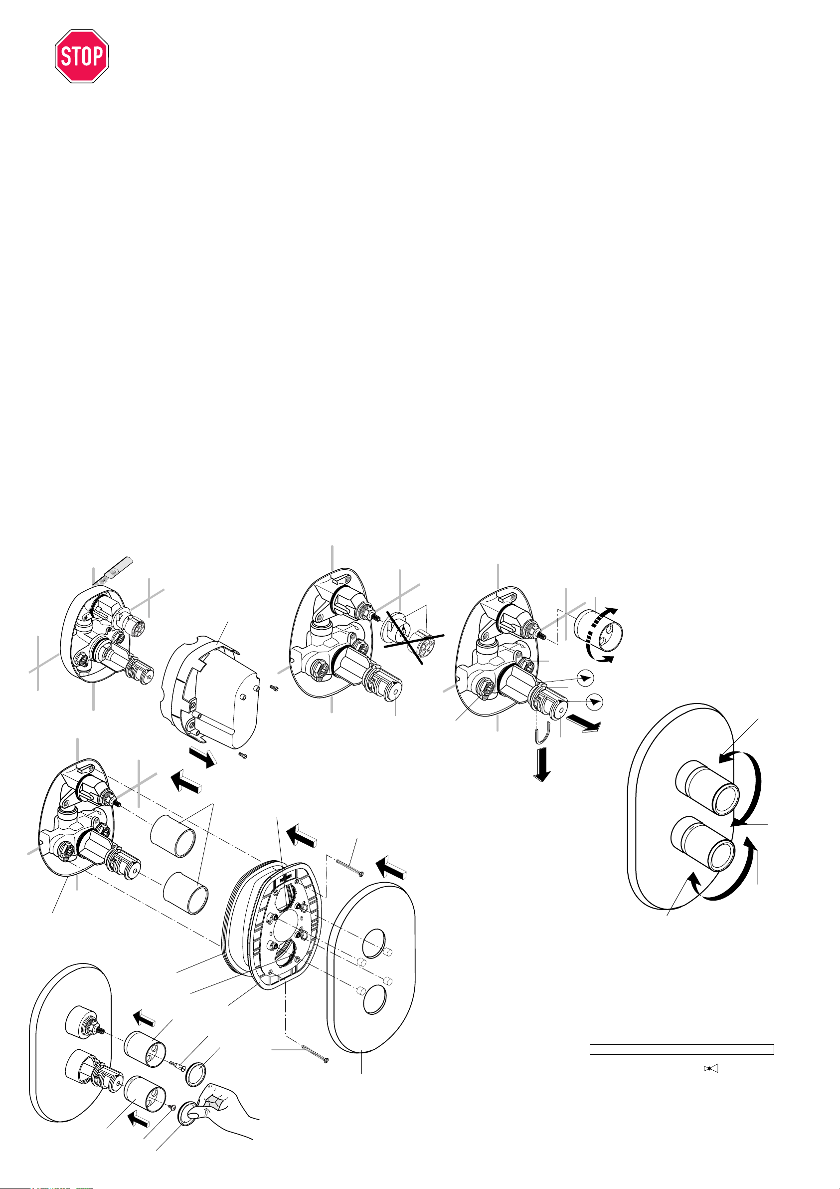
■Putzschablone 27 abschrauben. Überstehenden
Kragen des Dichtrahmens bündig zur Fliesen-
oberfläche abschneiden (siehe Bild I). Griffaufnahme
23 demontieren (siehe Bild II)
Kontrollieren,(sieheBild III / E) obdiePfeilmarkierung
E senkrecht nach oben zeigt. Wenn nicht, schwarze
Klammer des Sicherungsringes (siehe F) nach rechts
drücken, Teil 14 abziehen und in richtiger Position
wieder aufsetzen.
40 C-Justierung ( siehe Bild III ) Thermostat mit Griff
5 öffnen. Griffaufnahme 14 solange nach links o.
rechts drehen bis die Auslauftemperatur 40 C beträgt.
Thermostat schließen.
Kontrolle ( siehe Bild III ) Überprüfen, ob die Pfeil-
markierung D an der Griffaufnahme 14 nach der 40 C
Justierung nach oben zeigt. Sollte dies nicht der Fall
sein, den roten Riegel C nach unten herausziehen.
Teil 14 nach vorne abziehen und so aufstecken, daß
die Pfeilmarkierung D nach oben zeigt. Riegel C
wieder einsetzen.
Vertauschte Wasseranschlüsse ( Bild III ) Sollte
eine Justierung nicht möglich sein, weil die Wasserzu-
laufleitungen Warm + Kalt vertauscht angeschlossen
wordensind, ist folgendermaßen zu verfahren:Zulauf-
leitungen absperren. Rückschlageinheiten 19 und 24
ausbauen (SW 17) und vertauscht wieder einbauen.
Wichtig! - Einheit ROT, erkennbar am Sieb hinten -
sitzt nun rechts im Batteriekörper UP.
- Einheit BLAU, erkennbar am Sieb vorne
- sitzt nun links im Batteriekörper UP.
Zulaufleitungen wieder öffnen und 40 C - Justierung
wie oben beschrieben vornehmen.
Abdeckkappen 13 aufschieben (bis über den O - Ring,
siehe Bild IV). Dichtgummi 31 auf den Rosettenhalter
ziehen. Rosettenhalter 11 mit leicht eingefetteten O-
Ringen 12 über die Abdeckkappen und in den Dicht-
rahmen 31 schieben und mit den Schrauben 10 befe-
stigen. Rosette 9 aufdrücken.
Mengenregelgriff 5 aufstecken und mit der Schraube
4 befestigen.Temperaturgriff 3 auf Teil 14 schieben
und mit der Schraube 2 befestigen. Griffkappen 1
aufdrücken (Bild V).
■Screw off plaster guard ( 27 ).
Cut off projecting collar of the sealing frame flush with
the surface of the tiles ( see illustration I ). Remove
knop mount 23 (see illustration II).
Check that the arrow marking E points vertically
upward (see illustrations III / E). If not, push the black
clamp on the securing ring (see F) to the right, pull off
part 14 and re-install it in the correct position.
40˚C Adjustment (see illustrations III). Open the
thermostat with knop 5. Turn knob mount 14 clockwise
or anti-clockwise until the spout temperature is 40˚C.
Close the thermostat again.
Transposed supply piping (Illustration III). Should
the hot and cold water supply pipes have been
transposed, making adjustment impossible, proceed
as follows: Shut off water supply. Remove non-return
valves 19 and 24 (spanner size 17) and re-install them
transposed.
Important note:
RED valve, recognisable by the filter at the back - is
now installed on the right of the concealed mixer body.
BLUE valve, recognisable by the filter at the front, is
now installed on the left of the concealed mixer body.
Turn the water supply back on and perform the 40˚C
adjustment as described above.
Push on caps 13 over the O - rings as shown in Fig.
VI. Pull the rubber seal 31 onto the escutcheon hol-
der 11. Then push the escutcheon holder over the
caps and into the sealing frame 31, after lightly
greasing the o -rings 12, and screw it fast with the
screws 10. Then press on rose 9.
Push on flow-control knob 5 and screw tight with screw
4. Push temperature-control knob 3 onto part 14 and
screw tight with screw 2.Press on knob caps 1
(illustration V).
Check (see illustration III).
Check that the arrow marking D on the knob mount
14 still points upward after adjusting the thermostat
to 40˚C. If not, pull out the red locking device C
downwards. Now remove part 14 by pulling it towards
you whilst standing directly in front of the mixer unit
and then re-install it so that the arrow marking D points
upwards. Then re-insert locking device C.
■Dévisser le gabarit d'encastrement 27. Couper au
niveau des carreaux le collet du cadre d'étanchéité
qui dépasse ( fig. I ). Enlever le pièce 23 (fig.II).
Vérifier (figures III / E) si la flèche E se trouve bien
verticalement vers le haut. Dans le cas contraire,
pousser la pince noire du circlip vers la droite (voir F),
retirer la pièce 14 et la remettre dans la bonne position.
Réglage à40˚C(fig. III). Ovrir le thermostat avec pièce
5. Tourner vers la gauche ou vers la droite le support
de robinet 14 jusqu'àce que la température àla sortie
atteigne 40˚C. Fermer le thermostat.
Contrôle (figure III)
S'assurer que la flèche D sur le support de robinet 14
soit bien dirigée vers le haut après le réglage à40 C.
Dans le cas contraire, extraire vers le bas l'arceau C,
retirer la pièce 14 et l'emboîter ànouveau en mettant
la flèche D vers le haut. Remettre l'arceau en place.
Prises d'eau interchangées (figure III)
S'il devait être impossible de procéder au réglage
parce que les conduites d'arrivée d'eau chaude et
d'eau froide ont étéinversées, procéder comme suit:
fermer les conduites d'arrivée, démonter les unités
antiretour 19 et 24 (surplat 17) et les remonter en les
inversant.
Important! UnitéROUGE: identifiable au filtre placé
àl'arrière - se trouve désormais àdroite dans le corps
de mitigeur encastré. UnitéBLEUE, identifiable au
filtre placéàl'avant - se trouve désormais àgauche
dans le corps de mitigeur encastré.
Ouvrir ànouveau les conduites d'arrivée et procéder
au réglage à40˚C comme décrit précédemment.
Faire glisser les capuchons 13 (par dessus le joint
torique, fig. VI). Pousser le joint de caoutchouc 31
sur le support de rosette 11. Faire coulisser ce dernier,
avec les joints toriques 12 légèrement lubrifiés, sur
les capuchons, l'introduire dans le cadre d' étanchéité
31 et le fixer avec les vis 10. Enclencher la rosette 9.
Faire glisser la poignée de réglage du débit 5 et le
fixer avec les vis 4. Faire glisser la poignée de réglage
de la température 3 sur la pièce 14 et le fixer avec les
vis 2. Enfoncer le couvercle de robinet 1 (figure V).
■Svitare la sagoma da incasso 27. Rifilare il collare
sporgente della maschera di tenuta a filo delle
piastrelle ( vedi fig. I ). Togliere la testa portamanopola
23 (vedi fig.II).
Verificare (vedi fig.III / E) che le frecce di contrassegno
E siano rivolte verso l'alto e in caso contrario premere
verso destra il fermo nero dell'anello di bloccaggio
(vedi F), togliere l'elemento 14 e rimontarlo in posizione
corretta.
Regolazione della temperatura di 40˚C
(vedi fig.III) Aprire il miscelatore termostatico. Ora con
la testa portamanopola 14 portare la temperatura di
erogazione a 40˚C. Chiudere il miscelatore
termostatico.
Controllo (vedi fig. III)
Dopo aver eseguito la regolazione della temperatura
a 40˚C, verificare che la freccia di contrassegno D
della testa portamanopola 14 sia rivolta verso l'alto.
In caso contrario sfilare verso il basso la molla di
bloccaggio C. Togliere l'elemento 14 e rimontarlo con
la freccia D rivolta verso l'alto. Quindi rimontare anche
la molla di bloccaggio C.
Attacchi dell'acqua invertiti (fig. III)
Se, a causa dell'inversione dei tubi di alimentazione
dell'acqua fredda e calda, non fosse possibile
compiere una regolazione della temperatura di
erogazione, procedere come di seguito descritto:
chiudere innanzitutto entrambi i tubi di alimentazione.
Smontare le due valvole antiritorno 19 e 24 (chiave
del 17) rimontandole invertite.
Importante! La valvola ROSSA, riconoscibile dal filtro
posteriore verràmontata sulla destra del corpo del
gruppo. La valvola BLU, riconoscibile dal filtro
anteriore verràmontata sulla sinistra del corpo del
gruppo. Riaprire i tubi di alimentazione ed eseguire la
regolazione della temperatura di erogazione a 40˚C
come sopra descritto.
Inserire i cappucci 13 ( fino a coprire l' O-Ring, ved.
fig. VI). Tendere la guarnizione in gomma 31 sul
portarosetta. Spingere il portarosetta 11 con gli O -
Ring leggermente lubrificati sui cappucci e quindi nella
maschera di tenuta 31; fissare mediante le viti 10.
Applicare la rosetta 9.Infilare la manopola di
regolazione della portata 5 e fissare con la vite 4. Infine
montare a pressione il cappuccio 1. Infilare la
manopola di regolazione della temperatura 3
sull'elemento 14 e fissare con la vite 2. Infine montare
a pressione il cappuccio 1 ( fig. V) .
2Bedienung / Operation
Utilisation / Istruzioni sull'uso
auf
on
ouverture
aprire
zu
off
fermeture
chiudere
kalt / cold
froid / fredda
warm
hot
chaud
calda
I
Fertigmontage
Final assembly
Montage final
Montaggio finale
E
FD
II III
V
IV
Dichtrahmen
Sealing frame
Cadre d'étanchéité
Maschera de tenuta
Garantie nur bei Montage durch Fachmann.
Installation only by an expert.
Ne confier le montage qu'àun personnel spécialisé.
Far eseguire i lavori solo da un installatore.
Technische Daten / Technical data
Caractéristiques techniques / Dati tecnici
3
Betriebsdruck an der Armatur:
Operating pressure at the mixer unit:
Pression de service sur la robinetterie:
Pressione di esercizio sul gruppo:
max: 1 MPa ( 10 bar / 145 psi )
opt. : 0,1 MPa- 0,5 MPa (1 - 5 bar / 14,5-72,5 psi)
min: 0,1 MPa (1 bar / 14,5 psi)
> 0,5 MPa ( 5 bar / 72,5 psi )
➜
Prüfdruck:
Test pressure:
Pression d'essai:
Pressione massima
di prova:
1,6 MPa
(16 bar / 232 psi) max.
Durchflußleistung:
Flow rate:
Débit:
Portata:
0,3 MPa
(3 bar / 43,5 psi)
= 23 l/min
C
40
3
1
2
1
4
5

This manual suits for next models

1

Other Ideal-Standard Plumbing Product manuals

Ideal-Standard A 2659 NU User manual

Ideal-Standard

Ideal-Standard A 2659 NU User manual

Ideal-Standard IDEALTHERM A 5809 User manual

Ideal-Standard

Ideal-Standard IDEALTHERM A 5809 User manual

Ideal-Standard iLife T4870EO Instruction manual

Ideal-Standard

Ideal-Standard iLife T4870EO Instruction manual

Ideal-Standard HYGIENE PLUS Instruction manual

Ideal-Standard

Ideal-Standard HYGIENE PLUS Instruction manual

Ideal-Standard Ceratherm T25 User manual

Ideal-Standard

Ideal-Standard Ceratherm T25 User manual

Ideal-Standard PROSYS Comfort R0145 User manual

Ideal-Standard

Ideal-Standard PROSYS Comfort R0145 User manual

Ideal-Standard CONNECT 2 DOOR PV Instruction manual

Ideal-Standard

Ideal-Standard CONNECT 2 DOOR PV Instruction manual

Ideal-Standard ALCOVE Instruction manual

Ideal-Standard

Ideal-Standard ALCOVE Instruction manual

Ideal-Standard iLife T4875EO Instruction manual

Ideal-Standard

Ideal-Standard iLife T4875EO Instruction manual

Ideal-Standard CERAFLEX B C144 Series User manual

Ideal-Standard

Ideal-Standard CERAFLEX B C144 Series User manual

Ideal-Standard SEPTA PRO U1 User manual

Ideal-Standard

Ideal-Standard SEPTA PRO U1 User manual

Ideal-Standard LINDA-X T4626EN User manual

Ideal-Standard

Ideal-Standard LINDA-X T4626EN User manual

Ideal-Standard ULTRA FLAT S BESPOKE User manual

Ideal-Standard

Ideal-Standard ULTRA FLAT S BESPOKE User manual

Ideal-Standard iLife 2 T4887EO Instruction manual

Ideal-Standard

Ideal-Standard iLife 2 T4887EO Instruction manual

Ideal-Standard W3718AA User manual

Ideal-Standard

Ideal-Standard W3718AA User manual

Ideal-Standard SOTTINI TALENT User manual

Ideal-Standard

Ideal-Standard SOTTINI TALENT User manual

Ideal-Standard W3710 User manual

Ideal-Standard

Ideal-Standard W3710 User manual

Ideal-Standard Ceratherm T50 User manual

Ideal-Standard

Ideal-Standard Ceratherm T50 User manual

Ideal-Standard B 6928 AA Use and care manual

Ideal-Standard

Ideal-Standard B 6928 AA Use and care manual

Ideal-Standard Ceratherm C100 A7537AA User manual

Ideal-Standard

Ideal-Standard Ceratherm C100 A7537AA User manual

Ideal-Standard ULTRA FLAT NEW T4491 User manual

Ideal-Standard

Ideal-Standard ULTRA FLAT NEW T4491 User manual

Ideal-Standard W3718 Series User manual

Ideal-Standard

Ideal-Standard W3718 Series User manual

Ideal-Standard Ceratherm T125 User manual

Ideal-Standard

Ideal-Standard Ceratherm T125 User manual

Ideal-Standard K7061 Series User manual

Ideal-Standard

Ideal-Standard K7061 Series User manual

Popular Plumbing Product manuals by other brands

Hans Grohe Logis E 71403000 Assembly instructions

Hans Grohe

Hans Grohe Logis E 71403000 Assembly instructions

Hans Grohe Metris Classic Series Instructions for use/assembly instructions

Hans Grohe

Hans Grohe Metris Classic Series Instructions for use/assembly instructions

Schier GB-500 installation guide

Schier

Schier GB-500 installation guide

Pfister Privé F-534-7PV Quick installation guide

Pfister

Pfister Privé F-534-7PV Quick installation guide

KIBI F202 installation guide

KIBI

KIBI F202 installation guide

Nero Opal YSW2519-05D quick start guide

Nero

Nero Opal YSW2519-05D quick start guide

Price Pfister PARISA 39 Series Instruction sheets

Price Pfister

Price Pfister PARISA 39 Series Instruction sheets

Hans Grohe Talis E2 Series Instructions for use/assembly instructions

Hans Grohe

Hans Grohe Talis E2 Series Instructions for use/assembly instructions

Abode Harmonie AB1201 manual

Abode

Abode Harmonie AB1201 manual

Hans Grohe Ecos 31779007 Instructions for use/assembly instructions

Hans Grohe

Hans Grohe Ecos 31779007 Instructions for use/assembly instructions

Axor Starck Fixfit Deluxe 27451 Series Assembly instruction

Axor

Axor Starck Fixfit Deluxe 27451 Series Assembly instruction

Delinia MAXINE instruction manual

Delinia

Delinia MAXINE instruction manual

Hans Grohe MyFox 13154000 Instructions for use/assembly instructions

Hans Grohe

Hans Grohe MyFox 13154000 Instructions for use/assembly instructions

ROGERSELLER Viega More installation guide

ROGERSELLER

ROGERSELLER Viega More installation guide

Englefield MILANO 97516A-CP installation instructions

Englefield

Englefield MILANO 97516A-CP installation instructions

NOCH 56400 quick start guide

NOCH

NOCH 56400 quick start guide

Moen 135167 Series quick start guide

Moen

Moen 135167 Series quick start guide

FM Mattsson FMM Garda Instruction

FM Mattsson

FM Mattsson FMM Garda Instruction

manuals.online logo
manuals.online logoBrands
  • About & Mission
  • Contact us
  • Privacy Policy
  • Terms and Conditions

Copyright 2025 Manuals.Online. All Rights Reserved.