manuals.online logo
Brands
  1. Home
  2. •
  3. Brands
  4. •
  5. Ideal-Standard
  6. •
  7. Plumbing Product
  8. •
  9. Ideal-Standard IDEALTHERM A 5809 User manual

Ideal-Standard IDEALTHERM A 5809 User manual

TOP
Pro-Service
Euskirchener Straße 80
D-53121 BONN
Telefon ( 0228 ) 521580
Telefax ( 0228 ) 521581
Ihr Installateur / Your plumber / Votre installateur / L'installatore
Wandeinbau-Thermostat ( UP - Zentral ) G 1/2
Thermostatic bath / shower unit for wall mounting
Mitigeur thermostatique bain / douche a encastrer
Miscelatore termostatico vasca / doccia ad incasso
IDEALTHERM Junior
IDEALTHERM
Bausatz 2 / Kit 2 / Jeu de montage 2 / Kit di montaggio 2
für Fertigmontage / for final assembly / pour montage final / per montaggio finale
6weitere Arbeiten und Hinweise / Other work and information
Autres travaux et remarques / Successivi lavori ed istruzioni
■Nach Abschluß der Installationsarbeiten die
Zulaufleitungen absperren.
Achtung bei Frostgefahr!
Die Rohrleitungen sind so zu entleeren, daß in
den Armaturen sowie den dazugehörenden An-
schlußleitungen kein Restwasser verbleibt.
Fertimontage
erfolgt nach Abschluß der Putz- und Fliesen-
arbeiten. Der für die Endmontage benötigte
Bausatz 2 ist untenstehend ersichtlich.
Ersatzteile
sind in der Montageanleitung Bausatz 2 aufge-
führt.
■When installation work has been completed,
shut off the supply pipes.
Beware of freezing!
The pipes must be emptied so that no water
remains in the mixer units or their connection
pipes.
Final assembly
is performed after plastering and tiling work is
finished. Kit 2, which is required for final
assembly, is shown on the title page.
Spare parts
are listed in the Kit 2 installation instructions.
■Fermer les conduites d'arrivée une fois les
travaux d'installation terminés.
Attention en cas de risque de gel!
Purger les conduites jusqu'à ce qu'il ne reste
plus d'eau dans les robinetteries et dans les
tuyaux de raccordement correspondants.
Fin du montage
A faire une fois les travaux de crépi et la pose
des carreaux terminés.
Le kit 2 nécessaire pour la fin du montage est
illustré sur la page d'en-tête.
Pièces de rechange
Enumérées dans les instructions de montage
du kit 2.
■Una volta conclusi i lavori d'installazione,
chiudere i tubi di alimentazione dell'acqua.
Attenzione in caso di pericolo di gelo!
Le tubazioni dovranno essere svuotate in modo
che non rimanga acqua né nel gruppo né nelle
relative tubazioni di raccordo.
Fase finale dell'installazione
Questa fase è l'ultima dopo i lavori di
intonacatura e piastrellatura.
L'illustrazione del kit 2 per il montaggio finale è
riportata sulla prima pagina.
Pezzi di ricambio
Essi sono riportati nelle istruzioni per il
montaggio del kit 2.
Wichtig! Fliesenleger informieren - siehe Bilder I + II.
Important! Inform the tiler - see Figs. I + II.
Important! Informer le carreleur. Cf. schémas I + II.
Importante! Fornire le necessarie informazioni al piastrellista - ved. figure I + II.
30
20
150
165
230
168
85
42.5
66 - 88
42 - 64
G 1/2
G 1/2
G 1/2
G 1/2 24
150
170
232
163
85
42.5
66 - 88
42 - 64
G 1/2
G 1/2
G 1/2
G 1/2 24
30
20
150
170
230
180
85
42.5
66 - 88
42 - 64
G 1/2
G 1/2
G 1/2
G 1/2
30
20
24
150
170
230
166
85
42.5
66 - 88
42 - 64
G 1/2
G 1/2
G 1/2
G 1/2
30
20
24
Idealtherm
Idealtherm
Ceraron
Idealtherm
Ceratop
Idealtherm
Junior
Montage- und Bedienungsanleitung
InstallationInstructions
Instructions de montage
Istruzionidimontaggio
Dem Benutzer der Armatur aushändigen.
Please hand over to the user of the fitting.
S.V.P., remettre à l'utilisateur de la robinetterie.
Si prega di voler consegnare le presenti
istruzioni all'utilizzatore della rubinetteria.
A 953 981 A 5809 A 5814
Europa-Bestell-Nr. (z.B. A 2354 NU)
siehe Karton-Etikett.
For European article no. (e.g. A 2354 NU)
see label on the carton.
Pour Numéro d'article européen voir l'etiquette sur le carton
(p.ex. A 2354 NU).
Per il codice Europeo dell'articolo - vedi etichetta sul cartone
(p.es. A 2354 NU).
0109 / A 965 359
Made in Germany
Bausatz 1
für Vormontage im Rohbau
Kit1
for installation in the unfinished wall
Jeu de montage 1
pour prémontage dans le gros oeuvre
Kit di montaggio 1
per installazione sul rustico
TOP
II
Wand fertig verfliesen.
Finish tiling the wall.
Terminer le carrelage mural.
Piastrellare la parete.
I
Dichtrahmen aufkleben ( z. B. mit Deitermann
Superflex - 40 S ).
Glue on the sealing frame.
Coller le cadre d'étanchéité.
Applicare la cornice di tenuta.
Montage Dichtungs - Set / Installation of the seal set
Jeu d'étanchéité de montage / Montaggio set di guarnizioni
5
Wand fertig verputzt und vorbehandelt.
Ready plastered and pre-treated wall.
Mur crépi et préparé, prêt.
Parete intonacata e pretrattata.
Putzschablone- zum Fixieren des Dicht-
rahmens benutzen.
Use the plaster guard for fixing the sealing
frame.
Utiliser le gabarit d'encastrement pour fixer le
cadre d'étanchéité.
Cartuccia ad incasso - da utilizzare per il
fissaggio della cornice di tenuta.
TOP
Hersteller:
Ideal Standard
TOP
Vor Beginn der Montage bitte sorgfältig durchlesen.
Please read these instructions carefully before commencing installation.
Prière de lire attentivement cette notice avant de procéder àl'installation.
Prima di iniziare il montaggio leggare attentamente le seguenti istruzioni.
Montage nur durch Fachmann.
Installation only by an expert.
Ne confier le montage qu'àun personnel spécialisé.
Far eseguire i lavori solo da un installatore.
1
2
Warm
hot
chaud
calda
Kalt
cold
froid
fredda
Mischwasser
Mixed water
Mélange eau
chaude, eau froide
Acqua miscelata
22
I
Mischwasser
Mixed water
Mélange eau
chaude, eau froide
Acqua miscelata
A
■Positioning
It is essential to ensure that the pipes for cold
and hot water are connected to the correct inlet
sockets of the mixer body (see Figs. I).
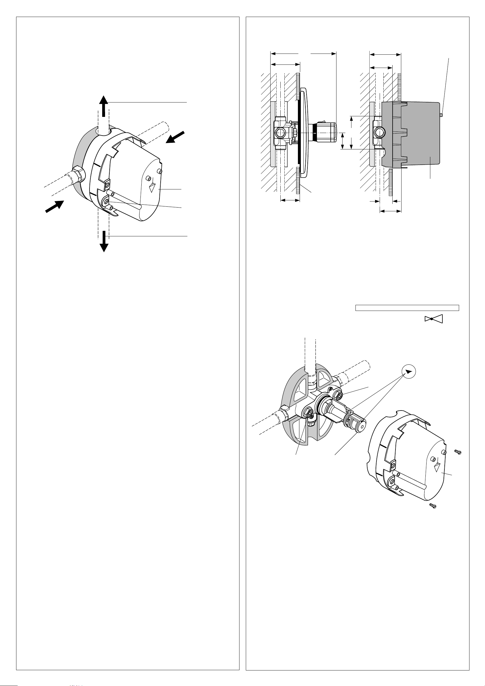
■Installation depth must be as shown in Fig.
II. The plaster guard has appropriate markings
for this purpose.
Installation
The mixer unit is supplied with plaster guard
screwed on and must be fitted in this state.
Ensure that the TOP marking on the plaster
guard faces upwards. Connect the pipes (all
connections G 1/2 ). Close off mixed water
connection if it is not required. Remove any dirt
in the supply pipes.
Important! Also install any required shutoff or
changeover valves into the pipe system.
When carrying out soldering in the vicinity of
the mixer body, remove the plaster quard and
all the parts which are in the body of the
concealed fitting to prevent any of the seals
being damaged.
When reassembling, ensure that the hot and
cold non-return valve units (Items 17 + 20) are
not transposed by mistake. Align the body of
the concealed fitting vertically and horizontally
using a spirit level (a special surface for resting
the spirit level is provided on the front of the
plaster guard) and secure the body.
■ Einbautiefe nach den Bildern II beachten.
Die Putzschablone hat hierfür Markierungen.
Montage
Die Thermostatbatterie wird mit angeschraub-
ter Putzschablone geliefert und ist so zu montie-
ren. Darauf achten, daßdie Markierung TOP an
der Putzschablone nach oben zeigt. Rohrleitun-
gen anschließen ( alle Anschlüsse =
G 1/2 ). Nicht benötigten Mischwasseran-
schlußverschließen.
Schmutz in den Zulaufleitungen entfernen.
Hinweis! - Benötigte Absperr- oder Umschalt-
ventile in das Rohrsystem mit einbauen.
Bei Lötarbeiten im Bereich des Batteriekörpers,
die Putzschablone sowie alle im alle im UP-
Körper befindlichen Teile ausbauen, damit kei-
ne Dichtungen zerstört werden können.
Beim Wiederzusammenbau darauf achten, daß
die Rückschlagventil - Einheiten Warm und Kalt
( Pos. 17 + 20 ) nicht vertauscht werden.
UP - Körper mit Hilfe einer Wasserwaage ( dazu
die Anlagefläche, Stirnseite der Putzschablone
benutzen ) senkrecht und waagerecht ausrich-
ten und befestigen.
■ Rohranschlüsse
Unbedingt darauf achten, daßdie Rohrleitun-
gen für Kalt- und Warmwasser am richtigen
Eingangsstutzen des Batteriekörpers ange-
schlossen werden ( Warmwasser = ROT, Kalt-
wasser = BLAU, siehe Fenster A - Bild I).
Der Mischwasser-Anschlußkann oben und un-
ten am Batteriekörper erfolgen.
■Positionnement
Toujours veiller àce que les conduites d'eau
chaude et d'eau froide soient branchées sur
les raccords correspondants du corps du
mitigeur (voir fig. I).
Avvertenza! - Non scordare di installare nelle
tubazioni le valvole d'intercettazione e di
commutazione necessarie. Qualora vengano
eseguiti lavori di brasatura nei pressi del
gruppo, smontare la sagoma da incasso e tutte
le parti del corpo incassato, in maniera da non
danneggiare le guarnizioni.
Rimontando i pezzi, prestare attenzione a non
scambiare le valvole antiritorno per l'acqua
calda e fredda ( pos. 17 + 20 ).
Allineare orizzontalmente e verticalmente il
corpo da incasso del gruppo con una livella a
bolla d'aria (quale superficie di riscontro
utilizzare la parte frontale della sagoma da
incasso) e quindi fissare.
■Rispettare la profonditàd'installazione
come alle figg. II.
Installazione
Il gruppo termostatico viene fornito con sagoma
da incasso avvitata e va installato cosìcome
fornito. Prestare attenzione che le tacche di
TOP siano rivolte verso l'alto. Eseguire il
collegamento ai tubi dell'acqua (tutti gli attacchi
hanno filettatture G 1/2 ).
Chiudere l'attacco dell'acqua miscelata non
utilizzato. Spurgare i tubi di alimentazione
dell'acqua in modo da eliminare tutte le impurità
presenti.
■Posizionamento
Accertarsi che i tubi per l'acqua calda e fredda
siano collegati correttamente ai rispettivi
manicotti del gruppo (vedi fig. I).
■Respecter la profondeur de montage
indiquée dans les illustrations II. Le gabarit
présente des repères spéciaux.
Montage
Le mitigeur àthermostat est livréavec un
gabarit d'encastrement visséet doit être monté
tel quel. Veiller àce que le repère TOP appliqué
sur le gabarit soit dirigévers le haut. Brancher
les conduites (tous les raccords G 1/2 ). Fermer
l'arrivée d'eau mélangée inutile.
Eliminer la saletépouvant se trouver dans les
conduites d'arrivée.
Remarque: Intégrer dans le système de
canalisation les soupapes d'arrêt ou soupapes
d'inversion nécessaires. Démonter le gabarit et
toutes les pièces se trouvant àl'intérieur du
corps encastréavant de faire les soudures
nécessaires àproximitédu corps du mitigeur
afin de ne pas détruire les joints.
Pour le réassemblage, ne pas inverser les
unités de clapet antiretour pour l'eau chaude
et pour l'eau froide ( Pos. 17 + 20 ).
Aligner àla verticale et àl'horizontale, puis fi-
xer le corps encastréàl'aide d'un niveau àbulle
d'air (en utilisant la surface d'appui àl'avant du
gabarit).
3Einbautiefe / Installation depth
Profondeurs de montage / Profonditàdi montaggio
30
20
168
66 - 88
42 - 64
64 max
85
42 min
66 min
88 max
42,5
II
Auflage für
Wasserwaage
fertige Wand
finished wall
mur terminé
rivestimento parete
Putzschablone
plaster guard
gabarit àenduit
sagoma da incasso
4
Prüfdruck:
Test pressure:
Pression d'essai:
Pressione massima di prova:
1,6 MPa ( 16 bar / 232 psi ) max.
Betriebstemperatur:
Temperature:
Température
d'utilisation:
Temperatura
d'esercizio:
80 C max.
Durchflußleistung:
Flow rate:
Débit:
Portata:
0,3 MPa ( 3 bar / 43,5 psi )
= 36 l/min
Betriebsdruck an der Armatur:
Operating pressure at the mixer unit:
Pression de service sur la robinetterie:
Pressione di esercizio sul gruppo:
max: 1 MPa ( 10 bar / 145 psi )
opt. : 0,1 MPa- 0,5 MPa (1 - 5 bar / 14,5-72,5 psi )
min: 0,1 MPa ( 1 bar / 14,5 psi )
> 0,5 MPa ( 5 bar / 72,5 psi ) ➜
Technische Daten / Technical data
Caractéristiques techniques / Dati tecnici
12
17
20
TOP
22
B
III
■Controllo: Il gruppo esce dalla fabbrica con
il rubinetto le valvole antiritorno 17 e 20 aperte.
In questo modo si garantisce il libero passaggio
dell'acqua da tutte le tubazioni collegate.
Controllo: Girare la testa portamanopola 12 ver-
so sinistra = massima erogazione acqua calda,
e verso destra = massima erogazione acqua
fredda. Terminato il controllo, girare i due
portamanopola 12 in modo che le frecce siano
rivolte verso l'alto (vedi B / fig. III).
■Vérification
La soupape d'arrêt et le préblocage 17 et 20
sont ouverts sur l'installation livrée par l'usine.
Il est donc possible que l'eau traverse toutes
les conduites branchées.
Contrôle - Tourner le support de robinet 12 vers
la gauche = arrivée d'eau chaude entièrement
ouverte, vers la droite = arrivée d'eau froide
entièrement ouverte.
Une fois le contrôle terminé, tourner le support
12 des poignée jusqu'àce que les flèches se
trouvent àla verticale vers le haut (voir B - figure
III). La robinetterie est alors fermée.
■ Prüfung Die Armatur wird werksseitig mit
geöffneter Vorabsperrung 17 und 20 geliefert.
Dadurch wird der freie Wasserdurchflußin allen
angeschlossenen Rohrleitungen möglich.
Kontrolle - Griffaufnahme 12 nach links drehen
= Warmwasser-, nach rechts = Kaltwasser-
Zulauf voll offen.
Nach Abschlußder Kontrolle ,Griffaufnahme 12
so drehen, daßdie Pfeilmarkierung senkrecht
nach oben stehen ( siehe B / Bild III ).
■ Check: The stop-valves 17 and 20 are
supplied in opened position.
Turn knob mount 12 clockwise and anti-
clockwise to simulteanously pressure-test the
subsequent piping.
After the test make sure that the arrow marking
on part 12 point vertically upwards
(see illustration B / III ).
30
40
40˚C
104°F
43˚C
109°F
45˚C
113°F
= 50˚C
118°F
°C max
0607 / A 965 600
30
40
40˚C
104°F
43˚C
109°F
45˚C
113°F
= 50˚C
118°F
°C max
0607 / A 965 600

This manual suits for next models

2

Other Ideal-Standard Plumbing Product manuals

Ideal-Standard Ceratherm T25 User manual

Ideal-Standard

Ideal-Standard Ceratherm T25 User manual

Ideal-Standard SOTTINI TALENT User manual

Ideal-Standard

Ideal-Standard SOTTINI TALENT User manual

Ideal-Standard ALCOVE Instruction manual

Ideal-Standard

Ideal-Standard ALCOVE Instruction manual

Ideal-Standard W3710 User manual

Ideal-Standard

Ideal-Standard W3710 User manual

Ideal-Standard CONNECT 2 DOOR PV Instruction manual

Ideal-Standard

Ideal-Standard CONNECT 2 DOOR PV Instruction manual

Ideal-Standard LINDA-X T4626EN User manual

Ideal-Standard

Ideal-Standard LINDA-X T4626EN User manual

Ideal-Standard iLife T4870EO Instruction manual

Ideal-Standard

Ideal-Standard iLife T4870EO Instruction manual

Ideal-Standard ULTRA FLAT NEW T4491 User manual

Ideal-Standard

Ideal-Standard ULTRA FLAT NEW T4491 User manual

Ideal-Standard B 6928 AA Use and care manual

Ideal-Standard

Ideal-Standard B 6928 AA Use and care manual

Ideal-Standard HYGIENE PLUS Instruction manual

Ideal-Standard

Ideal-Standard HYGIENE PLUS Instruction manual

Ideal-Standard K7061 Series User manual

Ideal-Standard

Ideal-Standard K7061 Series User manual

Ideal-Standard Ceratherm T125 User manual

Ideal-Standard

Ideal-Standard Ceratherm T125 User manual

Ideal-Standard TONIC User manual

Ideal-Standard

Ideal-Standard TONIC User manual

Ideal-Standard iLife 2 T4887EO Instruction manual

Ideal-Standard

Ideal-Standard iLife 2 T4887EO Instruction manual

Ideal-Standard E206567 Installation instructions

Ideal-Standard

Ideal-Standard E206567 Installation instructions

Ideal-Standard PROSYS Comfort R0145 User manual

Ideal-Standard

Ideal-Standard PROSYS Comfort R0145 User manual

Ideal-Standard Ceratherm T50 User manual

Ideal-Standard

Ideal-Standard Ceratherm T50 User manual

Ideal-Standard A 2659 NU User manual

Ideal-Standard

Ideal-Standard A 2659 NU User manual

Ideal-Standard Ceratherm C100 A7537AA User manual

Ideal-Standard

Ideal-Standard Ceratherm C100 A7537AA User manual

Ideal-Standard CERAMIX A 1100 Series User manual

Ideal-Standard

Ideal-Standard CERAMIX A 1100 Series User manual

Ideal-Standard A 5195 Series User manual

Ideal-Standard

Ideal-Standard A 5195 Series User manual

Ideal-Standard ULTRA FLAT S BESPOKE User manual

Ideal-Standard

Ideal-Standard ULTRA FLAT S BESPOKE User manual

Ideal-Standard CERAFLEX B C144 Series User manual

Ideal-Standard

Ideal-Standard CERAFLEX B C144 Series User manual

Ideal-Standard ULTRA FLAT NEW T449001 User manual

Ideal-Standard

Ideal-Standard ULTRA FLAT NEW T449001 User manual

Popular Plumbing Product manuals by other brands

DURAVIT N1 4382 Mounting instructions

DURAVIT

DURAVIT N1 4382 Mounting instructions

SunHome Luminar 2 Installation instructions manual

SunHome

SunHome Luminar 2 Installation instructions manual

wavin AS+ Technical manual

wavin

wavin AS+ Technical manual

NEC N8101-610F Installation and Handling Guide

NEC

NEC N8101-610F Installation and Handling Guide

Hans Grohe Metris M71 220 2jet 73800000 Instructions for use/assembly instructions

Hans Grohe

Hans Grohe Metris M71 220 2jet 73800000 Instructions for use/assembly instructions

Aquatica Digital Colonna-WS Installation & Care Manual

Aquatica Digital

Aquatica Digital Colonna-WS Installation & Care Manual

Kohler Iron Works K-2822 installation guide

Kohler

Kohler Iron Works K-2822 installation guide

Spectrum Brands Pfister Tisbury LG49-TB0Y Quick installation guide

Spectrum Brands

Spectrum Brands Pfister Tisbury LG49-TB0Y Quick installation guide

Pfister Treviso LF 48 Series install guide

Pfister

Pfister Treviso LF 48 Series install guide

Brizo Levoir T65798LF Series manual

Brizo

Brizo Levoir T65798LF Series manual

Spectrum Brands Pfister Push & Seal 972-097 Quick installation guide

Spectrum Brands

Spectrum Brands Pfister Push & Seal 972-097 Quick installation guide

Axor Starck FixFit Round 27451 Series Installation

Axor

Axor Starck FixFit Round 27451 Series Installation

American Standard Pekoe Single Control Kitchen Faucet 4332.001 Specification sheet

American Standard

American Standard Pekoe Single Control Kitchen Faucet 4332.001 Specification sheet

Villeroy & Boch Shape Assembly instructions

Villeroy & Boch

Villeroy & Boch Shape Assembly instructions

SaunaFit Indoor Western Red Cedar Assembly instructions

SaunaFit

SaunaFit Indoor Western Red Cedar Assembly instructions

Elkay EWCA4 Series Installation, care & use manual

Elkay

Elkay EWCA4 Series Installation, care & use manual

KEUCO 52773 010181 Mounting instruction

KEUCO

KEUCO 52773 010181 Mounting instruction

TLV VC Series instruction manual

TLV

TLV VC Series instruction manual

manuals.online logo
manuals.online logoBrands
  • About & Mission
  • Contact us
  • Privacy Policy
  • Terms and Conditions

Copyright 2025 Manuals.Online. All Rights Reserved.