IDT ZSSC41 Series User manual

ZSSC41xx SSC Evaluation Board User Guide
© 2019 Integrated Device Technology, Inc.
1
May 13, 2019
Important Notes
Disclaimer
Integrated Device Technology, Inc. and its affiliated companies (herein referred to as “IDT”) shall not be liable for any damages arising out of defects resulting from
(i) delivered hardware or software
(ii) non-observance of instructions contained in this manual and in any other documentation provided to user, or
(iii) misuse, abuse, use under abnormal conditions, or alteration by anyone other than IDT.
TO THE EXTENT PERMITTED BY LAW, IDT HEREBY EXPRESSLY DISCLAIMS AND USER EXPRESSLY WAIVES ANY AND ALL WARRANTIES, WHETHER
EXPRESS, IMPLIED, OR STATUTORY, INCLUDING, WITHOUT LIMITATION, IMPLIED WARRANTIES OF MERCHANTABILITY AND OF FITNESS FOR A
PARTICULAR PURPOSE, STATUTORY WARRANTY OF NON-INFRINGEMENT, AND ANY OTHER WARRANTY THAT MAY ARISE BY REASON OF USAGE
OF TRADE, CUSTOM, OR COURSE OF DEALING.
Restrictions in Use
IDT’s ZSSC41xx SSC Evaluation Kits, consisting of the SSC Communication Board (SSC-CB), ZSSC41xx SSC Evaluation Board (ZSSC41xx SSC EB), SSC
Sensor Replacement Board (SSC-SRB), and ZSSC41xx Evaluation Software, are designed for sensor module evaluation, laboratory setup, and module calibration
development only. IDT’s ZSSC41xx SSC Evaluation Kit hardware and software must not be used for module production or production test setups.
The related product ZSSC41xx SSC Mass Calibration System is designed only for development, evaluation, and laboratory setup of sensor modules with IDT
Sensor Signal Conditioner ICs. The IDT Mass Calibration System hardware and software must not be used for module production and production test setups.
Contents
1. Introduction...................................................................................................................................................................................................3
2. Hardware Description ...................................................................................................................................................................................4
2.1 Kit Overview.......................................................................................................................................................................................4
2.2 ZSSC41xx SSC Evaluation Board Overview .....................................................................................................................................5
3. Pin Descriptions for Board Connectors ........................................................................................................................................................7
3.1 Connections between the SSC Communication Board and the ZSSC41xx SSC Evaluation Board..................................................7
3.2 Connections between the Optional Sensor Replacement Board and the ZSSC41xx SSC Evaluation Board ...................................7
4. ZSSC41xx SSC Evaluation Board Schematic, Layout, and BOM................................................................................................................8
5. Related Websites and Software .................................................................................................................................................................13
6. Revision History..........................................................................................................................................................................................14

ZSSC41xx SSC Evaluation Board User Guide
© 2019 Integrated Device Technology, Inc.
2
May 13, 2019
List of Figures
Figure 1. ZSSC41xx SSC Evaluation Kit ............................................................................................................................................................3
Figure 2. Alternative User Sensor Module Connection Options .........................................................................................................................4
Figure 3. ZSSC41xx SSC Evaluation Board –Overview....................................................................................................................................5
Figure 4. ZSSC41xx SSC Evaluation Board Schematic.....................................................................................................................................8
Figure 5. ZSSC41xx SSC Evaluation Board Layout –Silkscreen ....................................................................................................................10
Figure 6. ZSSC41xx SSC Evaluation Board Layout –Top Side.......................................................................................................................11
Figure 7. ZSSC41xx SSC Evaluation Board Layout –Bottom Side .................................................................................................................12
List of Tables
Table 1. ZSSC41xx SSC Evaluation Board Connectors, Switches, and LEDs .................................................................................................5
Table 2. Signal Connections: ZSSC41xx SSC Evaluation Board and SSC Communication Board..................................................................7
Table 3. Signal Connections: ZSSC41xx SSC Evaluation Board and Sensor Replacement Board..................................................................7
Table 4. Bill of Materials for ZSSC41xx SSC Evaluation Board ........................................................................................................................9
ZSSC41xx SSC Evaluation Board User Guide
© 2019 Integrated Device Technology, Inc.
3
May 13, 2019
1. Introduction
The ZSSC41xx SSC Evaluation Board (ZSSC41xx SSC EB) is the main board in the modular ZSSC41xx SSC Evaluation Kits. These kits are
designed for sensor module evaluation, laboratory setup, and module calibration development for the ZSSC41xx Sensor Signal Conditioner
ICs (SSC), including the ZSSC4151, ZSSC4161, ZSSC4162, ZSSC4165, ZSSC4169 and ZSSC4175 (i.e., the device under test). Unless
otherwise noted, all references to the ZSSC41xx apply to these products.
Refer to the product-specific kit user manuals for the specific contents, hardware setup details, software setup, basic operation, and order codes
for the kits. Refer to the product-specific software manuals for full instructions for using the software for communication, calibration, configuration,
and evaluation of the device under test (DUT). These manuals and the product-specific software are available for download on the IDT web
pages for the specific products (see section 5).
The ZSSC41xx SSC Evaluation Kits contain the SSC Communication Board (SSC-CB), the ZSSC41xx SSC Evaluation Board, and the Sensor
Replacement Board (SSC-SRB). These boards can be connected in the following configurations:
The kit can be set up using the Sensor Replacement Board in place of a real sensor only for demonstration purposes as illustrated in
Figure 1 (see details in section 2.1).
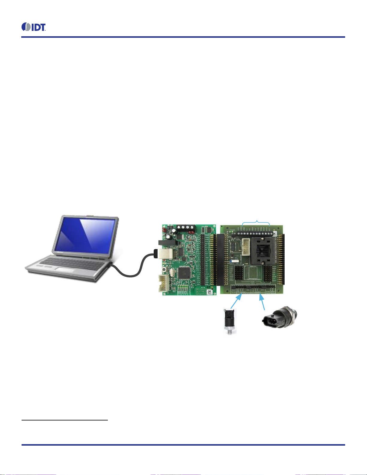
The user’s sensor can be connected on the KL1/KL2/KL3 screw terminals (see Figure 2) on the ZSSC41xx SSC Evaluation Board instead
of using the Sensor Replacement Board.
The “Sensor 1” or “Sensor 2” headers can be used to connect through the Evaluation Board to a complete user’s module (including the
user’s sensor, ZSSC41xx DUT, and external circuit); in this case, do not use the 24-QFN socket or Sensor Replacement Board.
Note: Sensor 2 is not applicable to the ZSSC4151.
Note: The SSC Communication Board (SSC-CB) must be version 4.1 with the current firmware version (see section 5) to function properly with
the ZSSC41xx SSC Evaluation Board.
Note: On delivery, the ZSSC41xx SSC Evaluation Board has a “dummy”IC in the socket that must be replaced with an actual ZSSC41xx DUT.
Refer to Figure 1 for the location of pin 1 for proper IC orientation.
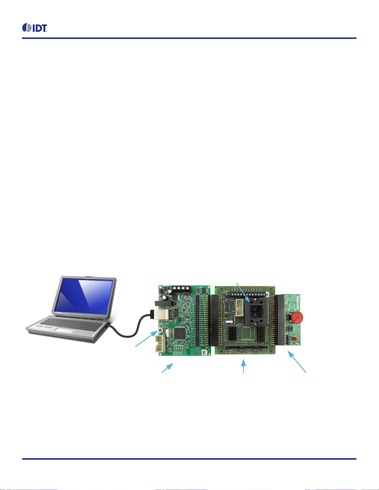
Figure 1. ZSSC41xx SSC Evaluation Kit
SSC Communication Board
(SSC-CB)
ZSSC415x/6x/7x
SSC Evaluation Board
(ZSSC41xx SSC EB)
Sensor Replacement Board
(SSC-SRB)
Reset
Pin 1
ZSSC41xx SSC Evaluation Board User Guide
© 2019 Integrated Device Technology, Inc.
4
May 13, 2019
2. Hardware Description
2.1 Kit Overview
A primary purpose of the ZSSC41xx Evaluation Kit is communication between the user’s computer and the ZSSC41xx DUT on the ZSSC41xx
SSC EB. The computer sends commands and data via its USB port (configured as a virtual COM port) to the SSC-CB. The microcontroller on
the SSC-CB interprets these commands and relays them to the ZSSC41xx in the I2C or OWI
*
(One-Wire Interface) communication mode. Refer
to the SSC Communication Board Datasheet for additional information about this board (see section 5).
The optional SSC-SRB provides a replacement for an actual resistive sensor and can be used for the first step of a calibration demonstration
or a “dry-run”calibration. On the SSC-SRB, the sensor replacement signal is controlled by a potentiometer and provides a signal ranging from
2mV to 110mV to the analog front-end of the ZSSC41xx (BR1N and BR1P pins) and a temperature sensor signal from a 1N4148 diode to the
ZSSC41xx temperature input (TS1 or TS2 pin, selectable by jumper K8, not applicable to the ZSSC4175D-01). Refer to the SSC Sensor
Replacement Board Datasheet for additional information about this board (see section 5).
The SENT (Single Edge Nibble Transmission) interface signal (not applicable to the ZSSC4151) is a one-way transmission of values from the
DUT to the SSC-CB microcontroller (intended for Normal Operation Mode only). The SENT interface allows high-resolution data transmission
with a lower system cost than other serial data solutions. If enabled (see Table 1), the “Sensor 2” header can be used as a SENT input from an
external user module for the ZSSC416x and ZSSC417x families (not applicable to the ZSSC4151). The “Sensor 1” header can be used for
either a SENT input (not applicable to ZSSC4151) or an OWI interface (required for ZSSC4151) for an external user module.
Figure 2. Alternative User Sensor Module Connection Options
Sensor Module
with AOUT/OWI
Sensor Module
with SENT
KL1/KL2/KL3: Optional screw terminals for
the user s sensor if the SSC-SRB is not used
The microcontroller will forward any data bytes from the ZSSC41xx back to the user’s computer via the USB connection. These bytes can be
sensor and temperature readings to be displayed by the software on the computer, raw analog-to-digital converter (ADC) data used during
calibration, or EEPROM data. The SSC-CB microcontroller controls the power signals required for entering the Command Mode.
The ZSSC41xx power (VDDE) can be supplied from the CB KS5V power supply (jumper K7 closed; see Figure 3) or from an external supply
(VDDE2) connected across the VDDE2 and VSSE post on the KL1 screw terminal (jumper K7 must be open).
Important: Ensure that jumper K7 is open before connecting an external VDDE2 power supply.
If connected, the VDDE2 supply can be switched ON or OFF by the CB-controlled KS5V signal and the IC4 power MOSFET as needed to
establish OWI communication.
*
OWI is also referred to as ZACwire™.

ZSSC41xx SSC Evaluation Board User Guide
© 2019 Integrated Device Technology, Inc.
5
May 13, 2019
The reset button on the SSC-CB (see Figure 1) sets the controller to its initial state. Note that any SSC-CB port settings will be overwritten.
The Mass Calibration Board DUT connector is intended for connecting the ZSSC41xx SSC Evaluation Board to a Mass Calibration Board (MCB)
for evaluation. The connector provides an I2C and OWI interface through the MCB and provides power to it.
Important: Do not connect the SSC-CB to the ZSSC41xx SSC EB if the MCB is used.
2.2 ZSSC41xx SSC Evaluation Board Overview
The operation of the ZSSC41xx SSC Evaluation Board is similar for all applicable products except as follows:
For the ZSSC4151, the S1 jumper identified in Figure 3 must be in the OWI position. SENT transmission is not applicable to this product.
For the ZSSC4151, the DOUT labels on the board and callouts in Figure 3 and in the schematic in Figure 4 refer to the ZSSC4151’s
AOUT pin.
The BR2N and BR2P pins do not apply to the ZSSC4151.
Figure 3. ZSSC41xx SSC Evaluation Board –Overview
Jumper K8:
Connects the external SSC-SRB temperature
sensor to the DUT s TS1 or TS2 inputs
KL1/KL2/KL3:
Screw terminals for optional external
supply and sensor bridges
K10: 50-pin connector
for SSC-SRB
24-QFN Socket
TSSOP16 Socket
(not mounted and not applicable)
Header Sensor 1: (K2, K1)
External module to CB-ADC1
Header Sensor 2: (K5, K9)
External module to CB-PE7
Bu1: 50-pin connector to SSC-CB
Switch S1: (socket s DOUT to CB-ADC1)
SENT: Connection through 120Ω(not applicable to ZSSC4151)
OWI: Direct connection
D1 LED: KS5V supply status
Jumper K7: Supply the VDDE pin for the QFN and TSSOP
sockets via KS5V (the TSSOP socket is not applicable)
Jumper Bu2: DOUT to GND
K6 Connector (4 x 7 pins)
Table 1. ZSSC41xx SSC Evaluation Board Connectors, Switches, and LEDs
Name
Description
D1
Status LED for the KS5V supply. Its forward current is not included in the measured supply current.
Bu1
50-pin female connector connected to the SSC-CB. See section 3.1 for descriptions of the signals on Bu1.
K10
50-pin male connector to the SSC-SRB. See section 3.2 for descriptions of the signals on K10.
ZSSC41xx SSC Evaluation Board User Guide
© 2019 Integrated Device Technology, Inc.
6
May 13, 2019
Name
Description
KL1
On-board screw terminal for GND (VSSE), VDDE2 (to VDDE), VDDA, and TS1 connections. (Note: The TS1 pin is not
applicable to the ZSSC4175D-01.)
KL2
On-board screw terminal for TS2, VSSA, TOP, and BR2P. (Note: The BR2P pin is not applicable to the ZSSC4151 and the
TS1 pin to the ZSSC4175D-01.)
KL3
On-board screw terminal for BR2N, BR1P, BR1N, and BOT. (Note: The BR2N pin is not applicable to the ZSSC4151.)
K1, K9
Powers (enables) the headers for connecting external Sensor 1 and Sensor 2 modules (K2 and K5 respectively) via KS5V.
K2, K5
Headers for connections for external Sensor 1 or Sensor 2 modules. Sensor 2 (K5) is intended only for SENT input one-way
transmission (Sensor 2 is not applicable to the ZSSC4151). The ZSSC4151 requires the OWI interface to use Sensor 1 (K2).
K4, K6
Header strips for access to all ZSSC41xx signals; K6 can be used to connect directly to the DUT for in-circuit programming.
K7
2-pin header for connecting the KS5V supply to the VDDE pin (leave jumper open when the external power supply VDDE2 is
connected); provides test points for simple supply current measurements.
K8
Connects the external SSC-SRB temperature sensor to the DUT’s TS1 or TS2 inputs. (Note: The TS1 and TS2 pins are not
applicable to the ZSSC4175D-01.)
S1
Switch that is used for interface selection between OWI and SENT. (Set to OWI for the ZSSC4151.)
24-QFN
Socket for inserting the 24-QFN 4mm 4mm ZSSC41xx DUT.
K11
Mass Calibration Board (MCB) DUT connector.

ZSSC41xx SSC Evaluation Board User Guide
© 2019 Integrated Device Technology, Inc.
7
May 13, 2019
3. Pin Descriptions for Board Connectors
3.1 Connections between the SSC Communication Board and the ZSSC41xx
SSC Evaluation Board
Table 2 gives the descriptions for the signals on the Bu1 connector (see Figure 3) that are applicable to the ZSSC41xx.
Table 2. Signal Connections: ZSSC41xx SSC Evaluation Board and SSC Communication Board
Bu1 Pin Name
Bu1 Pin
Description
5P
1
5V constant power supply.
KS5V
3
Power supply controlled by the microcontroller on the SSC-CB.
GND
2, 4, 6
Ground connection.
SCL, SDA
11, 13
I2C interface, 5V logic.
MOSI, MISO, SCK
17, 19, 21
SPI interface, 5V logic (used for ZSSC41xx SSC EB identification by I2C).
OWI
25
Bi-directional I/O port with ZSSC41xx-internal pull-up resistors; a pull-up resistor from KS5V with a
resistance of 4.7kΩ (on the SSC-CB) can be enabled by setting the SSC-CB microcontroller port pin
G3 low via the PS_G30 terminal command.
ADC1
27
One-Wire Interface (OWI) connection to the SSC-CB’s ADC1 (PA1).
PE7
28
Bi-directional I/O port with internal pull-up resistors.
Tr_PD2
39
Pull-up from KS5V with 510Ω resistor (R2) to the OWI line; enabled by setting the SSC-CB
microprocessor port pin D2 low via the PS_D20 terminal command during OWI communication.
PD4
43
Bi-directional I/O port with internal pull-up resistors.
PD6, PD7
47, 49
I2C 8-bit serial shift registers settings; set by the ZSSC41xx Evaluation Software.
3.2 Connections between the Optional Sensor Replacement Board and the
ZSSC41xx SSC Evaluation Board
Table 3 gives the descriptions for applicable signals on the K10 connector (see Figure 3).
Table 3. Signal Connections: ZSSC41xx SSC Evaluation Board and Sensor Replacement Board
K10 Pin Name
K10 Pin
Description
TOP
39, 45
Bridge and temperature sensor positive supply voltage
TS_U
41
Temperature sensor input (diode 1N4148)
BOT
43
Bridge negative supply voltage
BR1P
47
Bridge positive signal
BR1N
49
Bridge negative signal

ZSSC41xx SSC Evaluation Board User Guide
© 2019 Integrated Device Technology, Inc.
8
May 13, 2019
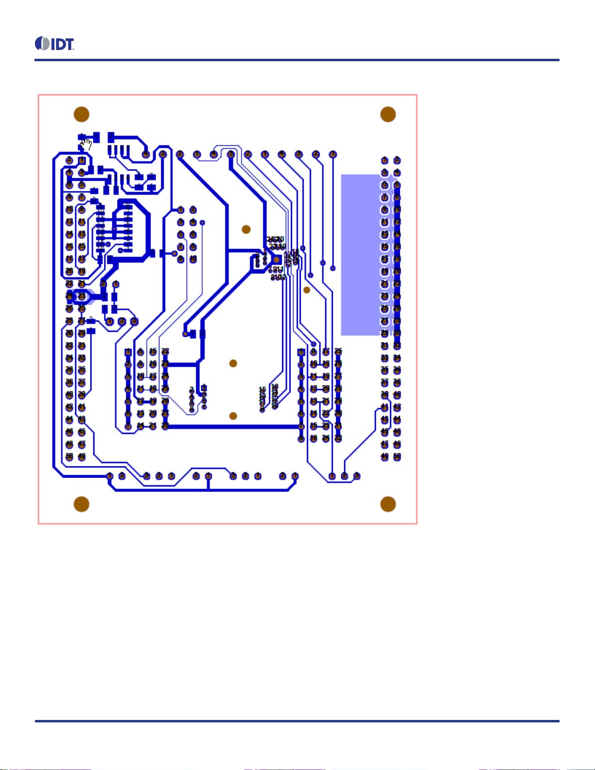
4. ZSSC41xx SSC Evaluation Board Schematic, Layout, and BOM
Figure 4. ZSSC41xx SSC Evaluation Board Schematic

ZSSC41xx SSC Evaluation Board User Guide
© 2019 Integrated Device Technology, Inc.
9
May 13, 2019
Table 4. Bill of Materials for ZSSC41xx SSC Evaluation Board
Designator
Value
Package
Manufacturer P/N
Supplier
Quantity
Bu1
SL2x25-90
WBUL50-GEW
BL 2X25W 2.54
Reichelt
Bu2
K1X2
1X02
SL 1X36G 2.54 z.B.
Reichelt
1
C1
100N
0805
X7R-G0805 100N
Reichelt
1
C2
100N
0805
X7R-G0805 100N
Reichelt
1
C3
2.2N
0805
X7R-G0805 2.2N
Reichelt
1
C4
100N
0805
X7R-G0805 100N
Reichelt
1
D1
LED 1206GN
1206-DIODE
SMD-LED 1206 GN
Reichelt
1
IC1
24-QFN Socket
24LQ50K14040
24LQ50K14040
Plastronics
1
IC2
74LS165ADR
SOIC16_150MIL
296-31854-1-ND
Digi-Key
1
IC4
IRF9389TRPBF
SMD8
IRF9389TRPBFCT-ND
Digi-Key
1
K1
K1X2
1X02
SL 1X36G 2.54 z.B.
Reichelt
1
K2
K1X3
1X03
M20-9990346
Farnell
1
K4
K4x8
4X08
M20-9980846
Farnell
1
K5
K1X3
1X03
M20-9990346
Farnell
1
K6
K4x7
4X07
M20-9980745
Farnell
1
K7
K1X2
1X02
SL 1X36G 2.54 z.B.
Reichelt
1
K8
K1X3
1X03
M20-9990346
Farnell
1
K9
K1X2
1X02
SL 1X36G 2.54 z.B.
Reichelt
1
K10
WSL-50POL_2x25
2X25-90
TSW-125-08-T-D-RA
Farnell
1
K11
MCB DUT
LH-10
WSL 10G
Reichelt
1
KL1
AKL 059-04
KLEMME-4RM3.5
AKL 059-04
Reichelt
1
KL2
AKL 059-04
KLEMME-4RM3.5
AKL 059-04
Reichelt
1
KL3
AKL 059-04
KLEMME-4RM3.5
AKL 059-04
Reichelt
1
R1
1.0K
0805
SMD-0805 1.00K
Reichelt
1
R2
510
0805
1400040
Farnell
1
R3
120
0805
SMD-0805 xxx
Reichelt
1
R4
10K
0805
SMD-0805 xxx
Reichelt
1
R5
5.6K
0805
SMD-0805 xxx
Reichelt
1
R6
120
0805
SMD-0805 xxx
Reichelt
1
R7
120
0805
SMD-0805 xxx
Reichelt
1

ZSSC41xx SSC Evaluation Board User Guide
© 2019 Integrated Device Technology, Inc.
10
May 13, 2019
Designator
Value
Package
Manufacturer P/N
Supplier
Quantity
R8
10K
0805
SMD-0805 xxx
Reichelt
1
S1
SCHIEB-1U-2.54
SCHIEB-1U-2.5
SS ESP101
Reichelt
1
Pad
Silicon Pads
1165068
Farnell
4
Figure 5. ZSSC41xx SSC Evaluation Board Layout –Silkscreen
ZSSC41xx SSC Evaluation Board User Guide
© 2019 Integrated Device Technology, Inc.
11
May 13, 2019
Figure 6. ZSSC41xx SSC Evaluation Board Layout –Top Side
ZSSC41xx SSC Evaluation Board User Guide
© 2019 Integrated Device Technology, Inc.
12
May 13, 2019
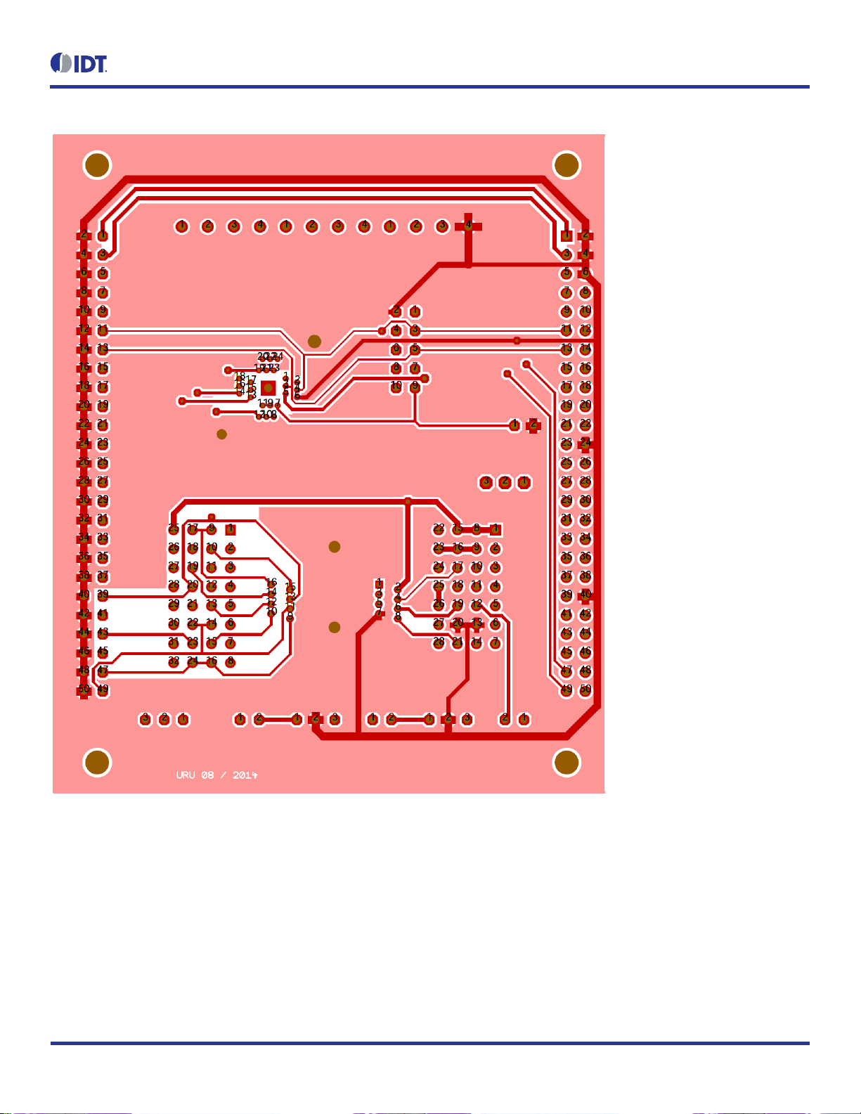
Figure 7. ZSSC41xx SSC Evaluation Board Layout –Bottom Side
ZSSC41xx SSC Evaluation Board User Guide
© 2019 Integrated Device Technology, Inc.
13
May 13, 2019
5. Related Websites and Software
Visit the specific product pages on IDT’s website www.IDT.com to download software/firmware, related documents, and the latest version of
this document, or contact IDT via the contact information on the last page.
Product
IC Product Web Page
Kit Product Web Page
ZSSC4151
www.IDT.com\ZSSC4151
www.IDT.com\zssc415xkit
ZSSC4161
www.IDT.com\ZSSC4161
www.IDT.com\zssc416xkit
ZSSC4162
www.IDT.com\ZSSC4162
www.IDT.com\zssc416xkit
ZSSC4165
www.IDT.com\ZSSC4165
www.IDT.com\zssc416xkit
ZSSC4169
www.IDT.com\ZSSC4169
www.IDT.com\zssc416xkit
ZSSC4175
www.IDT.com\ZSSC4175
www.IDT.com\zssc417xkit
SSC Communication Board (SSC-CB)
www.IDT.com\ssc-cb
Sensor Replacement Board (SSC-SRB)
www.IDT.com\ssc-srb
ZSSC41xx SSC Evaluation Board User Guide
© 2019 Integrated Device Technology, Inc.
14
May 13, 2019
6. Revision History
Revision Date
Description of Change
May 13, 2019
Complete document revision.
Ordering code table removed.
Product name changed to ZSSC41xx.
Minor edits and template update.
February 1, 2017
Merger of separate documents for ZSSC4151 and ZSSC416x/7x and rebranding for IDT. Revision
reference is now the document revision release date.
Addition of bill of materials and board layout images.
Addition of Figure 2 for user module connections.
Addition of order codes.
Minor edits and re-organization.
Corporate Headquarters
6024 Silver Creek Valley Road
San Jose, CA 95138
www.IDT.com
Sales
1-800-345-7015 or 408-284-8200
Fax: 408-284-2775
www.IDT.com/go/sales
Tech Support
www.IDT.com/go/support
DISCLAIMER Integrated Device Technology, Inc. (IDT) and its affiliated companies (herein referred to as “IDT”) reserve the right to modify the products and/or specifications described herein at any time,
without notice, at IDT's sole discretion. Performance specifications and operating parameters of the described products are determined in an independent state and are not guaran teed to perform the same
way when installed in customer products. The information contained herein is provided without representati on or warranty of any kind, whether express or implied, including, but not limited to, the suitability
of IDT's products for any particular purpose, an implied warranty of merchantability, or non-infringement of the intellectual property rights of others. This document is presented only as a guide and does not
convey any license under intellectual property rights of IDT or any third parties.
IDT's products are not intended for use in applications involving extreme environmental conditions or in life suppor t systems or similar devices where the failure or malfunction of an IDT product can be
reasonably expected to significantly affect the health or safety of users. Anyone using an IDT product in such a manner does so at their own risk, absent an express, written agreement by IDT.
Integrated Device Technology, IDT and the IDT logo are trademarks or registered trademarks of IDT and its subsidiaries in the United States and other countries. Other trademarks used herein are the
property of IDT or their respective third party owners. For datasheet type definitions and a glossary of common terms, visit www.idt.com/go/glossary. All contents of this document are copyright of Integrated
Device Technology, Inc. All rights reserved.
This manual suits for next models
8
Table of contents
Other IDT Motherboard manuals

IDT
IDT VersaClock 3S User manual

IDT
IDT Tsi381 User manual

IDT
IDT P9221-R-EVK User manual

IDT
IDT Tsi382 LQFP User manual

IDT
IDT 9FGV1006 User manual

IDT
IDT P9241-G-EVK User manual

IDT
IDT VersaClock 6 5P49V69 Series User manual

IDT
IDT 89EBPES16NT2 User manual

IDT
IDT ADC1410S Series User manual

IDT
IDT ZSSC4151 User manual

IDT
IDT P9221-R-EVK User manual

IDT
IDT 89EB-LOGAN-19 User manual

IDT
IDT 89EBPES48H12 User manual

IDT
IDT 8A34 Series User manual

IDT
IDT 89EBPES16T4G2 User manual

IDT
IDT PhiClock 9FGV1001 User manual

IDT
IDT EVK-UFT285-6-7 User manual

IDT
IDT ZWIR4532 User manual

IDT
IDT 5P49V5907 Manual

IDT
IDT ZSSC4151 User guide


