IDT ZWIR4532 User manual

ZWIR4532 Evaluation Kit User Manual
© 2018 Integrated Device Technology, Inc.
1
November 1, 2018
Description
The ZWIR4532 Development Kit is a set of three circuit boards
intendedasanevaluationandapplicationdevelopmentplatformfor
the ZWIR4532 6LoWPAN module. Each Development Board
providesanUSBinterfaceandanoptionalsingleEthernetinterface
to connect with the user's PC. The USB is used as a virtual COM
port and provides the power supply for JTAG programming and
debugging. The Ethernet interface is provided to easily integrate
the 6LoWPAN network into existing network infrastructure. Push
buttonsand LEDsare availableasan on-boarduser interface.The
application circuitry can be easily prototyped.
The Development Kit provides firmware libraries and example
programs. Firmware libraries include an operating system, IDT's
mesh-routing-enabled 6LoWPAN stack, IP-Security (IPSec) and
Internet Key Exchange version 2 (IKEv2) protocol support, as well
as support for over-the-air (OTA) updates and different peripheral
libraries. Ethernet gateway firmware is provided with the kit,
allowing transparent integration of sensor networks into existing
Ethernet networks.
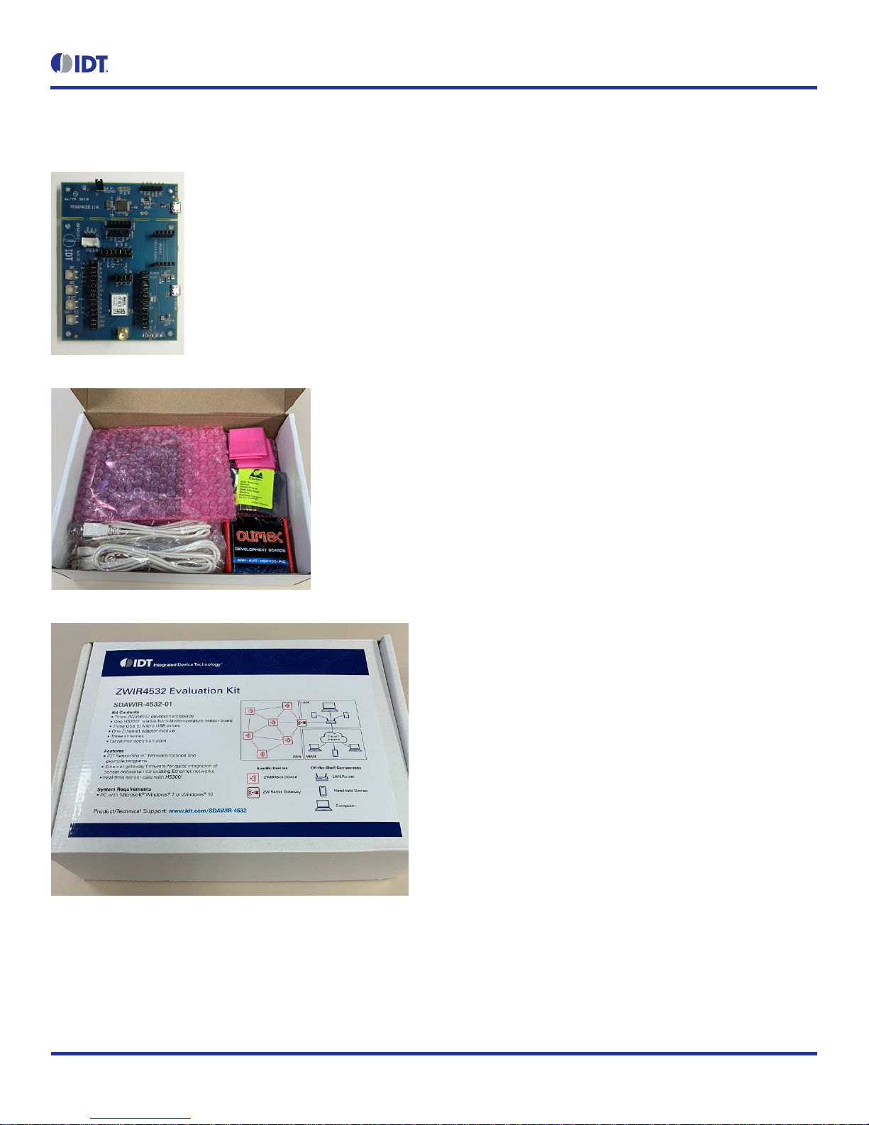
Kit Contents
3 ZWIR4532 development boards
3 HS3001 Humidity and Temperature sensors
3 USB to Micro USB cables
3 antennas
1 Ethernet adapter
Features
IDT SensorShare firmware libraries and example programs
License-free 868/915 MHz frequency bands
IPv6 module addressing
4 channels in EU mode; 10 channels in US mode
Over-the-air update (OTAU) functionality
Mesh connectivity
HS3001 Humidity and Temperature Sensor with I2C interface
in the Sensor Cube
•RH accuracy: ±1.5% RH typical (10% to 90% RH, 25°C)
•Fast RH response time (typical:6 seconds)
•Temperature sensor accuracy:±0.2°C (typ.) at -10°C to
+80°C
Related datasheets are available online:
•ZWIR4532: www.idt.com/ZWIR4532
•HS3001: www.idt.com/HS3001
•ENC28J60H Ethernet Adapter
https://www.olimex.com/Products/Modules/Ethernet/ENC2
8J60-H/resources/ENC28J60-H.pdf
•Microchip AT86RF212 Transceiver
http://ww1.microchip.com/downloads/en/DeviceDoc/doc81
68.pdf
•ST Micro STM32L071 MCU
https://www.st.com/resource/en/datasheet/stm32l071v8.pdf

ZWIR4532 Evaluation Kit User Manual
© 2018 Integrated Device Technology, Inc.
2
November 1, 2018
Important Notes
Disclaimer
Integrated Device Technology, Inc.and its affiliated companies (herein referred to as “IDT”) shall not be liable for any damages arising out of defects resulting from
(i) delivered hardware or software
(ii) non-observance of instructions contained in this manual and in any other documentation provided to user, or
(iii) misuse, abuse, use under abnormal conditions, or alteration by anyone other than IDT.
TO THE EXTENT PERMITTED BY LAW, IDT HEREBY EXPRESSLY DISCLAIMS AND USER EXPRESSLY WAIVES ANY AND ALL WARRANTIES, WHETHER
EXPRESS, IMPLIED, OR STATUTORY, INCLUDING, WITHOUT LIMITATION, IMPLIED WARRANTIES OF MERCHANTABILITY AND OF FITNESS FOR A
PARTICULAR PURPOSE, STATUTORY WARRANTY OF NON-INFRINGEMENT, AND ANY OTHER WARRANTY THAT MAY ARISE BY REASON OF USAGE
OF TRADE, CUSTOM, OR COURSE OF DEALING.
Restrictions in Use
IDT’s SDAWIR03 Demonstration Kit, consisting of the 6LoWPAN-WiFi Hub, Sensor Cube(s), AC/DC Wall Mount Adapters, Hose; USB and HDMI adapters, and
the IDT Demo Software, are designed to provide a quick setup for taking Flow, RH%, and temperature measurements with the FS2012 and HS3001 only. IDT’s
SDAWIR03 Demonstration Kits and IDT Demo Software must not be used for any mission-critical applications, end-customer products, or measurement reference
source.
Important Safety Warning: These procedures can result in high currents, which can cause severe injury or death
and/orequipment damage.Onlytrained professionalstaffshouldconnectexternal equipmentandoperatethe software.
Important Equipment Warning: Ensure the correct connection of all cables. Supplying the board using the wrong
polarity could result in damage to the board and/or the equipment. Check that all jumpers have been removed from
the board before applying power.
Contents
1. ZWIR4532 Evaluation Kit Components........................................................................................................................................................4
2. Setup............................................................................................................................................................................................................5
2.1 Computer Requirements.....................................................................................................................................................................5
2.2 Setting the Evaluation Kit to Interface the Computer...........................................................................................................................5
2.3 Evaluation Kit Board Connections.......................................................................................................................................................6
2.3.1 Antenna................................................................................................................................................................................6
2.3.2 Ethernet Connector..............................................................................................................................................................7
2.3.3 FS2012 Flow Sensor............................................................................................................................................................7
2.3.4 IDT Sensor Stick...................................................................................................................................................................7
2.3.5 Grove Sensor.......................................................................................................................................................................8
2.3.6 User Switch Connections .....................................................................................................................................................8
2.3.7 Reset and Boot Select Switch..............................................................................................................................................8
2.3.8 User LED Connections.........................................................................................................................................................8
!
!

ZWIR4532 Evaluation Kit User Manual
© 2018 Integrated Device Technology, Inc.
3
November 1, 2018
2.3.9 Miscellaneous Jumpers........................................................................................................................................................9
2.3.10 Jumper Locations on the PCB............................................................................................................................................10
2.4 Kit Power-Off and Operation.............................................................................................................................................................11
3. Schematics.................................................................................................................................................................................................11
4. Integrated Development Environment (IDE) Setup and Configuration.......................................................................................................20
4.1 Download Required Files..................................................................................................................................................................20
4.2 Installing CrossWorks for ARMand Obtaining an Evaluation License..............................................................................................20
4.3 Setting Up Required Libraries and the ZWIR4532 Board Support Package.....................................................................................20
5. Hello World Test Program..........................................................................................................................................................................21
5.1 Creating a New Project......................................................................................................................................................................21
5.2Compiling, Loading and Executing the Project..................................................................................................................................21
6. Ordering Information...................................................................................................................................................................................22
7. Revision History..........................................................................................................................................................................................22
List of Figures
Figure 1. Evaluation Kit Board Connections.......................................................................................................................................................6
Figure 2. Jumper Locations..............................................................................................................................................................................10
ZWIR4532 Evaluation Kit User Manual
© 2018 Integrated Device Technology, Inc.
4
November 1, 2018
1. ZWIR4532 Evaluation Kit Components
ZWIR4532 Evaluation Kit User Manual
© 2018 Integrated Device Technology, Inc.
5
November 1, 2018
2. Setup
2.1 Computer Requirements
Windows 7, Windows 8 and Windows 10; 32-bit and 64-bit aresupported. The selection of the development program may limit these choices.
2.2 Setting the Evaluation Kit to Interface the Computer
The connection to the evaluation kit is via the computers USBport operating asa serial COMx device. This driver needs to be installed prior to
plugging this Evaluation Kit intothe PC. ST Micro provides the driver to do this.
1. Connect to www.st.com.
2. In search tab in the upper rightcorner enter ST-LINK/V2.
3. Click on the STSW-LIN009 option.
4. On the bottom of the page, select the Get Software option and follow the instructions.
5. ST Micro will ask for some information to execute the download.
6. Unzip the download.
7. Execute the resulting .bat file topermit installing the correct version (32-bit or 64-bit).
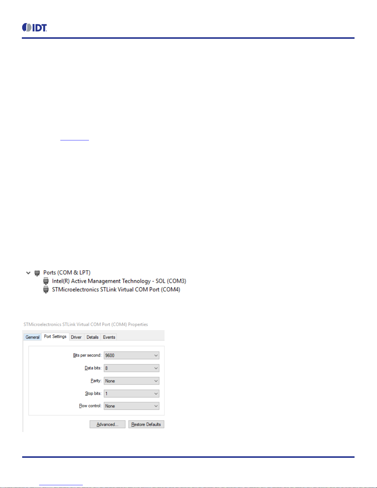
When the evaluation kit is plugged into the PC, the COM LED on the Programming Link part of the board will illuminate:
Flashing indicates the USB connection is not correct
Continuously on indicates a working USB connection
The Control Panel and theDevice Manager option on the PCwill show the connection and theCOM port being used. For example, this shows
a COM4 connection:
Typical port settings will defaultto:
ZWIR4532 Evaluation Kit User Manual
© 2018 Integrated Device Technology, Inc.
6
November 1, 2018
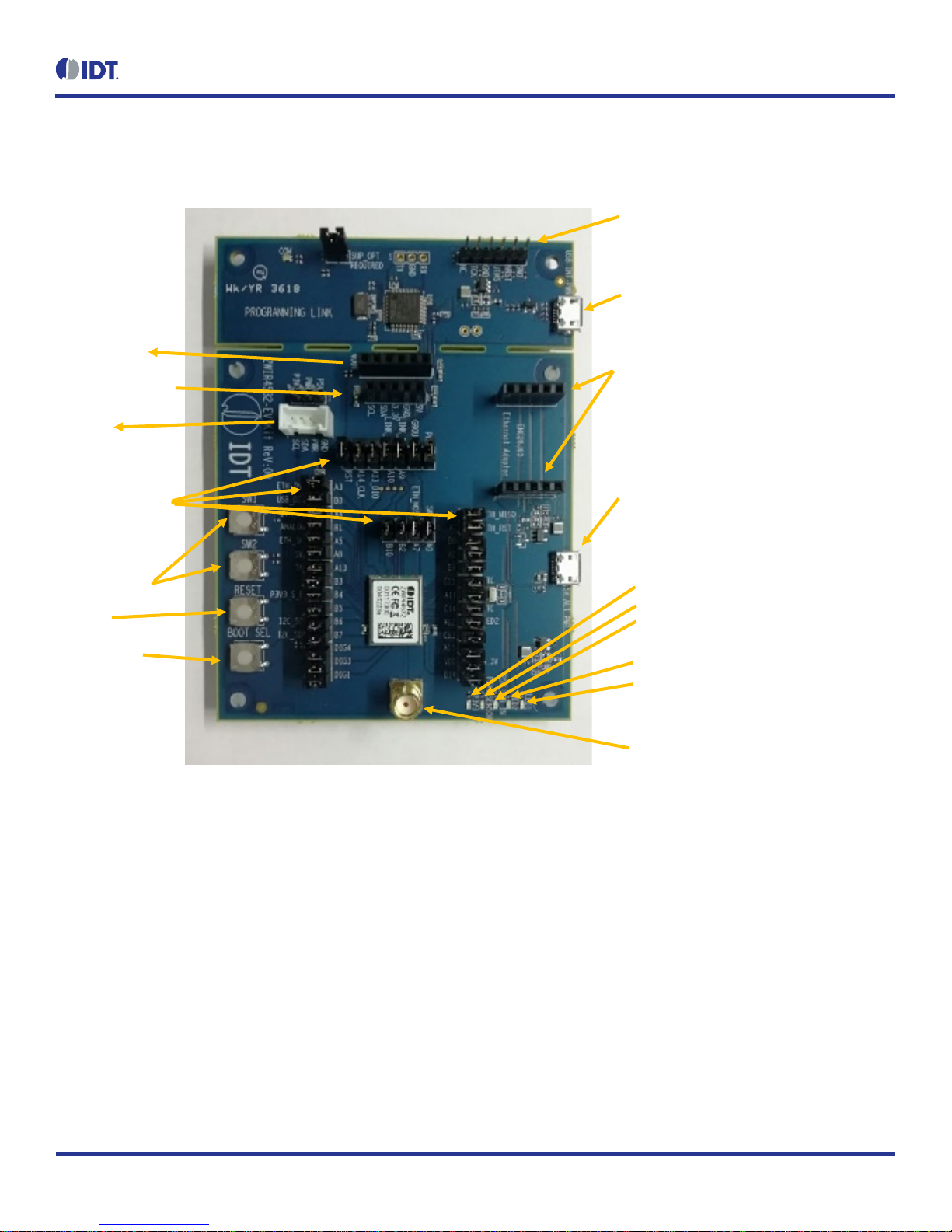
2.3 Evaluation Kit Board Connections
Figure 1. Evaluation Kit Board Connections
2.3.1 Antenna
The antenna is to be 50Ωand examples are supplied in the evaluation kit. There is no matching network on the evaluation kit PCB if matching
is needed for other antennas–this has to be done after the SMAconnector.
I2C Sensor
Connectors:
IDT FS2012
IDT Sensor Stick
Grove
JTAG programming connection.
Only used if the two sections
are separated
USB control connection and
kit power
Antenna SMA Connector
UserSwitches
Reset
Boot Select
Auxiliary Power via USB cable. Use
only when programming
board is
separated from the EV Kit board
Ethernet Adapter connector
Indicator LEDs
3.3V to ZWIR4532
3.3V to Sensors
USB 5V input
User LED2
User LED1
Various
Jumpersto alter
the EV Kit setup

ZWIR4532 Evaluation Kit User Manual
© 2018 Integrated Device Technology, Inc.
7
November 1, 2018
2.3.2 Ethernet Connector
The ZWIR4532 accepts the Ethernet expansionmodule ENC28J60-G (supplied in the evaluation kit).
Ethernet Connector
Pin Function Via Jumper ZWIR4532 Pad Function
J18-1 SCK J27 16 A5
J18-2 MOSI J29 34 A7
J18-3 MISO J28 33 A6
J18-4 WOL NC --- ---
J18-5 INT J26 14 A3
J19-5 (6) CLKOUT NC --- ---
J19-4 (7) CS J25 14 A4
J19-3 (8) RST J24 6 A1
J19-2 (9) GND --- --- ---
J19-1 (10) 3.3V --- --- ---
2.3.3 FS2012 Flow Sensor
FS2012 Flow Sensor
Pin Function Via Jumper ZWIR4532 Pad Function
J20-1 VDD 5V (USB) --- --- ---
J20-2 I2C – SDA J12 43 B7
J20-3 I2C – SCL J11 42 B6
J20-4 GND --- --- ---
J20-5 NC --- --- ---
J20-6 VOUT Resistors R22, R23; J34 38 B1
2.3.4 IDT Sensor Stick
IDT Sensor Stick
Pin Function Via Jumper ZWIR4532 Pad Function
J36-1 VDD 5V (USB) --- --- ---
J36-2 GND --- --- ---
J36-3 3.3V Sensors --- --- ---
J36-4 I2C – SDA J12 43 B7
J36-5 I2C – SCL J11 42 B6
5 NC --- --- ---

ZWIR4532 Evaluation Kit User Manual
© 2018 Integrated Device Technology, Inc.
8
November 1, 2018
2.3.5 Grove Sensor
Grove Sensor
Pin Function Via Jumper ZWIR4532 Pad Function
J21-1 I2C – SCL J11 42 B6
J21-2 I2C – SDA J12 43 B7
J21-3 VDD 5V (USB) or 3.3V
Sensor J55 (next to
connector) --- ---
J21-4 GND --- --- ---
2.3.6 User Switch Connections
Switch Function Via Jumper ZWIR4532 Pad Function
SW1 N.O. to GND
Soft pull-up to 3.3V J33 11 A9
SW2 N.O. to 3.3V
Soft pull-down to GND J43 7 A0
2.3.7 Reset and Boot Select Switch
Switch Function ZWIR4532 Pad Function
SW3 RESET N.O. to GND 8 RST
SW4 BOOT_SEL N.O. to 3.3V 13 BSEL
2.3.8 User LED Connections
LED Function Via Jumper ZWIR4532 Pad Function
LED1 High Level is LED ON J31 30 A11
LED2 High Level is LED ON J43 29 A12

ZWIR4532 Evaluation Kit User Manual
© 2018 Integrated Device Technology, Inc.
9
November 1, 2018
2.3.9 Miscellaneous Jumpers
Signals which are not committed to a function are connected to dual-row jumpers. The pin not connected to the ZWIR4532 isa no connection.
Jumper ZWIR4532 Pad Function
J30 23 DIG1
J41 22 DIG3
J56 21 DIG4
J39 5 A2
J45 28 A15
J46 35 B2
J47 40 B3
J10 19 B5
J48 32 B8
J49 31 B9
J50 36 B10
J51 27 B14
J52 2 PC13
J7 (connects 32.768kHz time crystal) 3 PC14
J8 (connects 32.768kHz time crystal) 4 PC15
ZWIR4532 Evaluation Kit User Manual
© 2018 Integrated Device Technology, Inc.
10
November 1, 2018
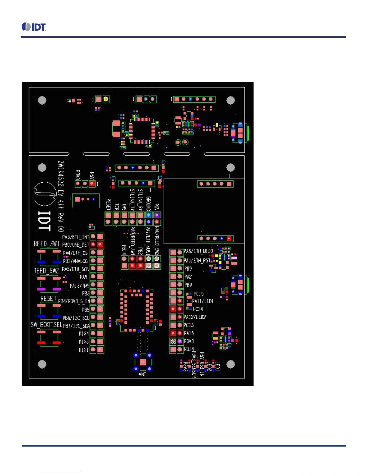
2.3.10 Jumper Locations on the PCB
Figure 2. Jumper Locations
ZWIR4532 Evaluation Kit User Manual
© 2018 Integrated Device Technology, Inc.
11
November 1, 2018
2.4 Kit Power-Off and Operation
TheZWIR4532 evaluationkit willshow asa USBconnected item.It isbest todo aUSB ejectof thedevice andthen extracttheUSB cablefrom
the PC.
If the evaluation kit boards have been separated and the Auxiliary USB power connector is being used (no true USB connection to the PC),
simply unplug the cable to power off the evaluation kit.
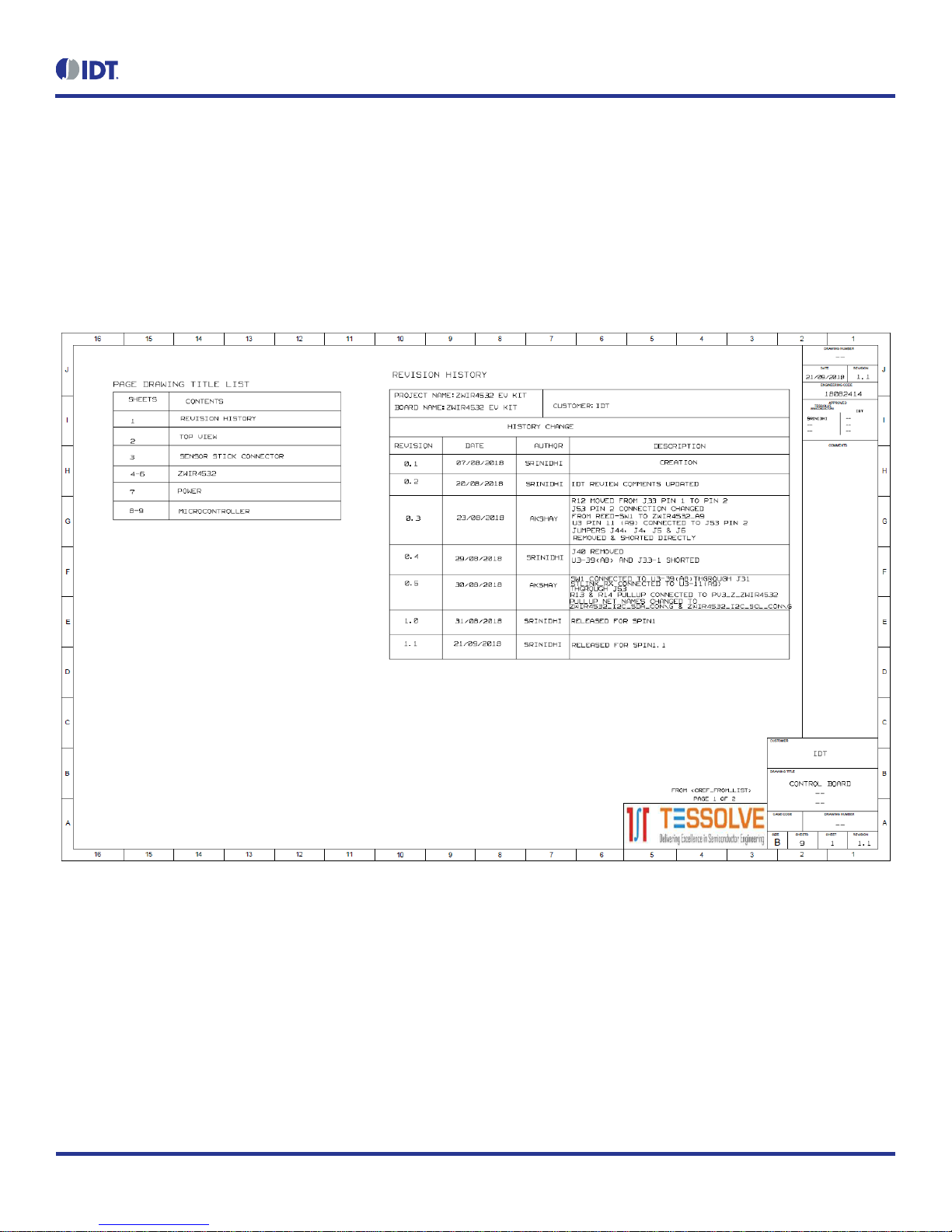
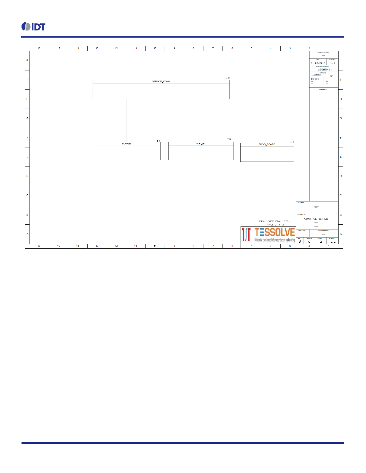
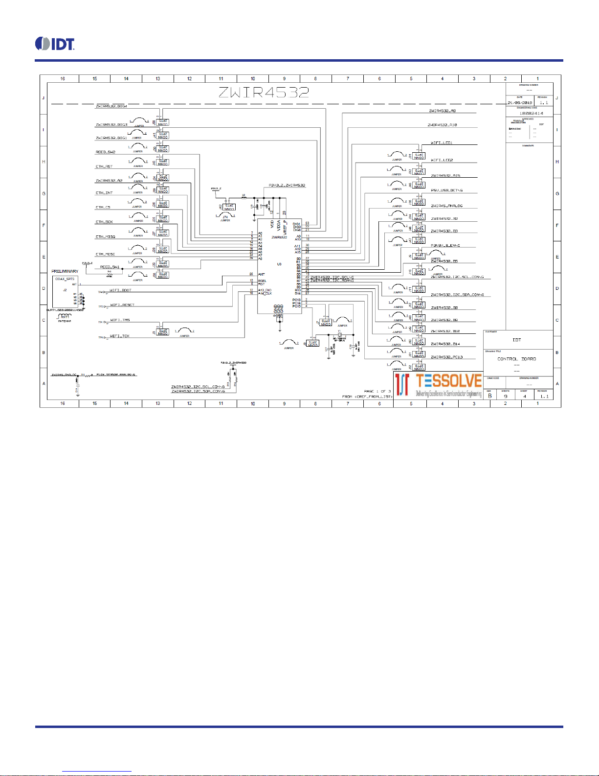
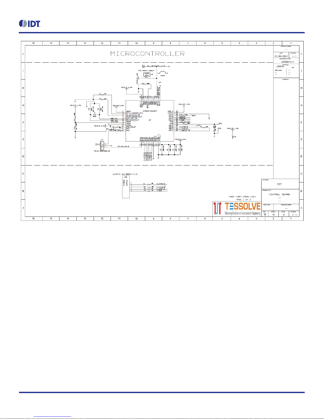
3. Schematics
ZWIR4532 Evaluation Kit User Manual
© 2018 Integrated Device Technology, Inc.
12
November 1, 2018

ZWIR4532 Evaluation Kit User Manual
© 2018 Integrated Device Technology, Inc.
13
November 1, 2018
ZWIR4532 Evaluation Kit User Manual
© 2018 Integrated Device Technology, Inc.
14
November 1, 2018

ZWIR4532 Evaluation Kit User Manual
© 2018 Integrated Device Technology, Inc.
15
November 1, 2018

ZWIR4532 Evaluation Kit User Manual
© 2018 Integrated Device Technology, Inc.
16
November 1, 2018

ZWIR4532 Evaluation Kit User Manual
© 2018 Integrated Device Technology, Inc.
17
November 1, 2018
ZWIR4532 Evaluation Kit User Manual
© 2018 Integrated Device Technology, Inc.
18
November 1, 2018

ZWIR4532 Evaluation Kit User Manual
© 2018 Integrated Device Technology, Inc.
19
November 1, 2018

ZWIR4532 Evaluation Kit User Manual
© 2018 Integrated Device Technology, Inc.
20
November 1, 2018
4. Integrated Development Environment (IDE) Setup and Configuration
This document assumes Rowley CrossWorks for ARM is a commercial toolchain available for Windows and Linux. It provides an integrated
development environment (IDE) and a debugger. IDT provides board support packages for ZWIR45xx modules to allow for quick and easy
project setup.
4.1 Download Required Files
1. Download CrossStudio from https://www.rowley.co.uk/arm/index.htm.
2. Download ZWIR4532 FirmwarePackage.zip from IDT.com and unzip to a directory of your choice.
3. Download ST-Link Drivers from ST.com.
4.2 Installing CrossWorks for ARM and Obtaining an Evaluation License
1. Run the installation. Note that the installation requires administrator privileges.
2. Start the CrossStudio IDE.
3. From the main menu bar, select “Tools”“License Manager”.
4. Choose “Evaluate Crossworks”.
5. Select “Primary operating system disk”as the item to which to lock your license.
6. Click on the “Send e-mail”button and wait for reception of your activation key byemail –note that this may take some time.
7. After reception of the activation,copy the email contents to theclipboard.
8. Go back to CrossStudio and open the License Manager again.
9. Choose “Activate CrossWorks”.
10. Paste the clipboard contents in the “Enter activation key”textbox (usually the clipboard contentis already there).
11. Click on “Install License”.
12. Click “Close”.
4.3 Setting Up Required Libraries and the ZWIR4532 Board Support Package
1. From the main menu bar, select “Tools”“Package Manager”.
2. Find the “STM32 CPU SupportPackage” and mark for installation by double-clicking or right-clicking and “Install Selected Package”.
3. Click “Next” button twice followed by “Finish”.
4. From the main menu bar, select “Tools”“Packages” “Manually Install Packages…”.
5. Navigate to the directory wherethe ZWIR4532 Firmware Package has been unzipped.
6. Select the “ZWIR4532 Board Support Package”and click open.
Table of contents
Other IDT Motherboard manuals

IDT
IDT Tsi381 User manual

IDT
IDT EB-LOGAN-23 User manual

IDT
IDT EVK-UFT285-6-7 User manual

IDT
IDT ZSSC41 Series User manual

IDT
IDT 8A34 Series User manual

IDT
IDT EB8T5A Eval Board User manual

IDT
IDT 82P33731 User manual

IDT
IDT VersaClock 6E 5P49V6965 User manual

IDT
IDT 8T49N240 User manual

IDT
IDT VersaClock 3S User manual

IDT
IDT P9241-G-EVK User manual

IDT
IDT PhiClock 9FGV1001 User manual

IDT
IDT P9242-G-EVK User manual

IDT
IDT 9FGV1005 Operating instructions

IDT
IDT 82P33714 User manual

IDT
IDT VersaClock 6 5P49V69 Series User manual

IDT
IDT P9221-R-EVK User manual

IDT
IDT 9FGV1006 User manual

IDT
IDT 89EB-LOGAN-19 User manual

IDT
IDT Tsi382 LQFP User manual


