Norco MITX-6946 User manual

MITX-6946
Mini-ITX Motherboard
User’ Manual V2.0

MITX-6946 Based on Intel Braswell Platform Mini-ITX Motherboard
1
Announcement
With the exception of showing the accessories of product configuration, this
manual does not create any commitment of our company. We retained the
rights to change it without prior notice and will not be responsible for any
direct, indirect, intentional or unintentional damage or hidden dangers
caused by any improper installation or use.
Before buying products, please learn about the product performance from
the distributors to see if it is in line with your needs. NORCO is a registered
trademark of Shenzhen NORCO Intelligent Technology CO., LTD. The
ownership of other trademarks involved in this manual is owned by its
respective owners.
The contents of this manual are protected by copyright law. All rights are
strictly reserved. Any form of unauthorized reproduction is prohibited,
including but not limited to carbon copy, facsimile transmission and
electronic copy or email, etc.

MITX-6946 Based on Intel Braswell Platform Mini-ITX Motherboard
2
Safety Instructions
1.Before using this product, please read this user’s manual carefully;
2.Any plate cards not ready to be installed shall be kept in the anti-static protective bags;
3.Before taking out the plate cards from the anti-static protective bags, first place hands on the
grounding metal object for a while so as to release the static electricity from your body and
hands;
4.While fetching the plate cards, please wear static protective gloves and have the habit of
holding the cards by edge;
5.Before connecting the motherboard to the power supply, please check the power voltage
6.In order to prevent bodily electric shock or damage to products, first turn off the
AC power or unplug the power cord out of power sockets while inserting main boards or plate
cards or do reconfiguration;
7.Before moving the plate cards or the unit, please make sure to unplug the AC power cords
out of the sockets;
8.Before you connect or unplug any equipment, please make sure that all power cords are
unplugged in advance;
9.To prevent any unnecessary damage to the products due to frequent power on/off. Please
wait at least 30 seconds before you restart up the unit after the unit is shut down;
10.If anything unexpected happened during the operating, please seek help from
professionals;
11.This is a Class A product, in a domestic environment, this product may cause radio
interference. In this case, the user may be required to take adequate measures.

MITX-6946 Based on Intel Braswell Platform Mini-ITX Motherboard
3
Content
Chapter 1 Product Introduction...........................................................................................................1
1.1 Introduction.................................................................................................................................1
1.2 Product Specification................................................................................................................ 1
Chapter 2 Installation Instructions.........................................................................................................3
2.1 Interface Location and Dimension Diagram..........................................................................3
2.2 Installation Steps....................................................................................................................... 3
2.3 CPU & Memory Installation......................................................................................................4
2.4 Jumper Setting...........................................................................................................................4
2.4.1 CMOS Content Clearance /Keep Settings(JCC)................................................ 4
2.4.2 Hardware Switch for System Auto Boot upon Power On(JAT)..........................6
2.4.3 COM2 Jumper Setting(J1,J2)............................................................................. 6
2.4.4 USB8 and Mini PCIE Selection Jumper Setting J4.................................................. 8
2.4.5 SATA2 and MSATA Selection Jumper SettingJ 6、J7............................................. 8
2.5 Interface Specification........................................................................................................... 9
2.5.1 SATA Interface(SATA1、SATA2、PWR_OUT)................................................ 9
2.5.2 Serial Ports(COM1、COM2)................................................................................ 10
2.5.3 Display Interface(VGA、DVI、LVDS/HDMI)................................................... 11
2.5.4 LVDS Voltage and Backlight Setting Interface(LVDS_BKLT、JLVDS)................. 13
2.5.5 USB Ports(USB_LAN1、USB_LAN2、USB56、USB78).............................. 14
2.5.6 Keyboard & Mouse Connector(KBMS)............................................................... 15
2.5.7 Programmable I / O interface(JGP).....................................................................16
2.5.8 Power Connector(PWR2)......................................................................................17
2.5.9 FAN Connector(CPU_FAN).................................................................................. 18
2.5.10 JLPC Interface(JLPC)..........................................................................................19
2.5.11 Audio Interface(JACKHDA)................................................................................21
2.5.12 SCM Programming Interface(J13).....................................................................21
2.5.13 Front Panel Connector(JFP).............................................................................. 22
2.5.14 Memory Slot(SO-DIMM)......................................................................................23
2.5.15 Expansion Interface(PCIE_X1、MINI_ PCIE).................................................23
MITX-6946 Based on Intel Braswell Platform Mini-ITX Motherboard
4
Chapter 3 BIOS Setup.......................................................................................................................26
AMI BIOS Upgrading.............................................................................................................26
AMI BIOS Description...........................................................................................................26
BIOS Parameter Configuration............................................................................................26
3.1 Main Menu................................................................................................................................27
3.2 Advanced..................................................................................................................................28
3.2.1 ACPI Settings............................................................................................................... 30
3.2.2 Supper IO Configuration.............................................................................................31
3.2.3 H/W Monitor.................................................................................................................34
3.2.4 Serial Port Console Redirection................................................................................ 35
3.2.5 CPU Configuration.......................................................................................................38
3.2.6 PPM Configuration...................................................................................................... 40
3.2.7 SATA Configuration.....................................................................................................41
3.2.8 Miscellaneous Configuration......................................................................................42
3.2.9 LPSS & SCC Configuration........................................................................................43
3.2.10 Network Stack Configuration................................................................................... 44
3.2.11 CSM Configuration.................................................................................................... 45
3.2.12 USB Configuration....................................................................................................46
3.3 Chipset Menu...........................................................................................................................48
3.3.1 North Bridge.................................................................................................................49
3.3.2 South Bridge................................................................................................................ 50
3.4 Boot Menu................................................................................................................................ 51
3.5 Security Menu..........................................................................................................................52
3.6 Save&Exit Menu......................................................................................................................53
Appendix................................................................................................................................................. 38
Appendix 1:Watchdog Programming Guide........................................................................... 38
Appendix 2:Glossary.................................................................................................................. 40

MITX-6946 Based on Intel Braswell Platform Mini-ITX Motherboard
1
Chapter 1 Product introduction
1.1 Introduction
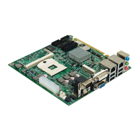
MITX-6946 is a standard Mini-ITX specification motherboard,with Intel Braswell chip set,
on board N3060/N3160/ N3710 N series processors;1x single channel SO_DIMM slot,support
DDR3L 1066/1333/1600,memory up to 8GB. Interfaces:1x standard DB15 VGA display
interface.1xstandard DVI interface、1x 2x8Pin 2.0mm HDMI pin interface and 1xdual-channel
18/24bit LVDS interfaces.(alternative with HDMI)、2xstandard 7 Pin SATA interfaces(SATA2
and MSATA alternative)、2x standard DB9 COM interface,can expand to 10COM via LPC、
8x USB ports,in which 2x standard USB 2.0 ports and 2x standard USB 3.0 ports,2x 2×5Pin
2.54mm pin that can be converted into 4xstandard USB 2.0 ports、2xGigabit Ethernet
interfaces,with Realtek RTL8111F Gigabit Ethernet Chip、1x standard Mini PCIE interface,
default support MSATA equipment、8xGPIO. Flexible input or output functions to extend
multiple functional interfaces.
1.2 Product Specification
Structural standards
●Standard Mini-ITX motherboard
Size
●170mm×170mm(L×W)
Processor
●N3060/N3160/N3710 processor
Chip set
●Intel Braswell
Display
●VGA:1x standard DB15 interface,Maximum resolution: 1920×1200@60Hz
●DVI:1x standard DVI interface,Maximum resolution: 2560*1440 @60Hz
●LVDS:1xstandard dual-channel 18/24bit LVDS interface, maximum resolution :
1920*1200@60Hz

MITX-6946 Based on Intel Braswell Platform Mini-ITX Motherboard
2
●HDMI:1x2x8Pin 2.0mm Pin interface,Maximum resolution: 3840*2160@30Hz
Note:HDMI and LVDS alternative
Memory
●1x single channel SO-DIMM slot,support DDR3L 10661333/1600,memory up to 8GB.
Storage
●2x standard 7 Pin SATA interfaces,in which SATA2 and MSATA are alternative.
LAN Function
●Network controller:2x RTL8111F Gigabit Ethernet Chip
●2x standard RJ45 interfaces ●Rate:10/100/1000Mbps
USB ports
●Provide 8xUSB ports ●2x standard USB 2.0 ports (default,USB3.0 optional)、
2x standard USB 3.0 ports、2x 2×5Pin 2.54mm pin,can transfer to 4x standard USB 2.0 ports.
I/0 function
●W83627DHG-P chip set ●2x serial interfaces, COM1 and COM2 are standard DB9
serial interfaces, both support RS232 model, COM2 also support RS485 model
Power supply
●Single power supply:3Pin DC Jack(default)
Watch dog
●Support hardware reset
BIOS
●8MB SPI BIOS
Environment
●Operating Temperature:0℃~60℃●Storage Temperature:-40℃~80℃
●Humidity:5% ~ 95% RH, non-condensing

Chapter
Two
Install
ation
Instruc
tion

MITX-6948 User Manual
3
Chapter 2 Installation Instruction
2.1 Interface Location and Dimension Diagram
The following picture is the interface index for MITX-6946。when you install your
devices, please consult it and read the following guide. During installation please
care for some devices. Improper installation will lead to system malfunctions.
Note:During installation, in order to protect the parts of the board, please put
on anti-static gloves.
MITX-6946 Interface Location and Dimension Diagram
2.2 Installation Steps
Please refer to the following steps to install your computer:
1.Adjust all Jumpers on MITX-6946 according to the manual;
2.Install CPU and memory;
3.Install other expansion cards;

MITX-6948 User Manual
4
4.Connect all the signal lines, cable, panel-control circuitry and power supply;
5.Start the computer,finish BIOS setup.
Key components of this motherboard are Integrated circuit, and these components
will be easily damaged by electrostatic influence. So, before installing the motherboard,
you should always keep the following precautions in mind:
1.Hold the board by the edges; don't touch any components or pins on the board.
2.Use a anti-static wrist strap or wear anti-static gloves while getting in touch with integrated
circuit components (such as CPU, RAM).
3.Place components in a grounded anti-static bag/pad when these components are
uninstalled.
4.Please make sure the power switch is disconnected before inserting the power plug.
2.3 CPU & Memory Installation
This motherboard is equipped with 1xDDR3Lslot.Please pay attention to the following two
points when installing memory bank:
1.When fixing, make sure the notch matches SO-DIMM socket and then insert memory bank
into the socket. Press it down to tight the connection.
2.Choose the proper memory bank that supports motherboard specification。
2.4 Jumper Setting
Please setup the jumpers accordingly before installing hardware devices.
Note: How to identify jumper and PIN1 of interface
Please observe the word mark of plug socket, it will use “1”or bold line or triangular
symbols; and please look at the back of PCB,each weld spot has a squar point, that is PIN 1;
Usually there is a withe arrow beside PIN 1.
2.4.1 CMOS Content Clearance /Hold Setting(JCC)
CMOS powered by on board button battery. Clean CMOS will lead to a permanent
elimination of the previous system setting and back to the original (default setting) system
settings.
Steps :(1)Turn off the computer, disconnect the power supply ;
(2)Use jumper cap short JCC Pin 1 and Pin 2 for 5~6 sec,Then restore the default
setting of Pin2 and Pin 3.;;

MITX-6948 User Manual
5
(3)Turn on the computer, then press DEL key into the BIOS setting and reload the
optimized defaults;
(4)Save and exit setting.
JCC:
Setting
JCC
1-2
Clear CMOS(BIOS renew to initialization)
2-3
Normal status(default)
Do not clear CMOS when power on, otherwise it will damage the motherboard!
JCC

MITX-6948 User Manual
6
2.4.2 Hardware Switch for System Auto Boot upon Power On(JAT)
JAT:
Setting
JAT
Open
Disable this auto boot function
Close
Enable this auto boot function
2.4.3 COM2 Jumper Setting(J1,J2)
J1 ,J2 jumpers are used to configure COM2 transmission mode. COM2 supports
RS232/RS485,you can choose settings based on your own needs, default mode as RS232。
JAT

MITX-6948 User Manual
7
J1、J2:
COM2 RS232(default)
COM2 RS485
J1
1-3 2-4
3-5 4-6
J2
1-2
3-4 5-6
J1、J2

MITX-6948 User Manual
8
2.4.4 USB8 and Mini PCIE Selection Jumper Setting J4
J4:
J4
USB8(default)
Mini PCIE
1-3 2-4
3-5 4-6
2.4.5 SATA2 and MSATA Selection Jumper Setting J6、J7
J4
J6、J7

MITX-6948 User Manual
9
J6、J7:
MSATA(default)
SATA2
J6
1-3 2-4
3-5 4-6
J7
1-3 2-4
3-5 4-6
2.5 Interface Specification
Please read this manual first before connecting external connectors in case of any
damage to the motherboard!
2.5.1 SATA Interface(SATA1、SATA2、PWR_OUT)
Provide 2xstandard 7 Pin SATA interfaces(SATA2 and MSATA alternative). Provide 1x
5Pin hard disk power supply voltage interface,when using, you need to connect the tie line to
the hard disk by the SATA hard disk power interface (PWROUT).
SATA:
Pin
Signal Name
1
GND
2
TX+
3
TX-
SATA1、SATA2
PWR_OUT

MITX-6948 User Manual
10
4
GND
5
RX-
6
RX+
7
GND
PWROUT:
Pin
Signal Name
1
VCC3
2
GND
3
VCC
4
GND
5
+12V
2.5.2 Serial Interfaces(COM1、COM2)
Provide 2x standard DB9 serial interfaces.. In which COM1 and COM2 both support
RS232 model,COM2 also support RS485 model.
COM1 RS232:
Pin
Signal Name
COM1、COM2

MITX-6948 User Manual
11
1
DCD
2
RXD
3
TXD
4
DTR
5
GND
6
DSR
7
RTS
8
CTS
9
RI
When COM2 is set to RS232/RS485, its pins are defined as follows:
Pin
RS232(default)
RS485
1
DCD
DATA-
2
RXD
DATA+
3
TXD
NC
4
DTR
NC
5
GND
GND
6
DSR
NC
7
RTS
NC
8
CTS
NC
9
RI
NC
2.5.3 Display interfaces(VGA、DVI、LVDS/HDMI)
Provide 1x standard DB15 VGA display interface(reserve 1x2×5 Pin JVGA pin)、 1x
standard DVI interface 、1x dual-channel 18/24bit LVDS interface 、1x 2x8Pin 2.0mm HDMI
interface,alternative with LVDS.

MITX-6948 User Manual
12
LVDS:
Signal Name
Pin
Signal Name
VDD_PANEL
1
2
VDD_PANEL
GND
3
4
GND
LVDSA_DATA0#
5
6
LVDSB_DATA0#
LVDSA_DATA0
7
8
LVDSB_DATA0
GND
9
10
GND
LVDSA_DATA1#
11
12
LVDSB_DATA1#
LVDSA_DATA1
13
14
LVDSB_DATA1
GND
15
16
GND
LVDSA_DATA2#
17
18
LVDSB_DATA2#
LVDSA_DATA2
19
20
LVDSB_DATA2
GND
21
22
GND
LVDSA_CLK#
23
24
LVDSB_CLK#
LVDSA_CLK
25
26
LVDSB_CLK
GND
27
28
GND
LVDS_DDC_DATA
29
30
LVDS_DDC_CLK
GND
31
32
GND
LVDSA_DATA3#
33
34
LVDSA_DATA3#
LVDSA_DATA3
35
36
LVDSA_DATA3
VGA_DVI
JVGA
LVDS
HDMI

MITX-6948 User Manual
13
GND
37
38
GND
NC
39
40
NC
HDMI:
Signal Name
Pin
Signal Name
HDMI_DATA0_R_DP
1
2
HDMI_CLK_R_DP
HDMI_DATA0_R_DN
3
4
HDMI_CLK_R_DN
GND
5
6
GND
HDMI_DATA1_R_DP
7
8
HDMI_SCL
HDMI_DATA1_R_DN
9
10
HDMI_SDA
GND
11
12
GND
HDMI_DATA2_R_DP
13
14
HDMI_DETECT
HDMI_DATA2_R_DN
15
16
VCC
2.5.4 LVDS Voltage and backlight setting Interface (LVDS_BKLT、JLVDS)
LVDS_BKLT:
LVDS Backlight voltage and control signal setting
Signal Name
Pin
Signal Name
+12V
1
2
BLUP
LVDS_BKLT
JLVDS
Table of contents
Other Norco Motherboard manuals

Norco
Norco SOM-6503 User manual

Norco
Norco MITX-6854 User manual

Norco
Norco BPC-7971 User manual

Norco
Norco BPC-7936 User manual

Norco
Norco MITX-6922 User manual

Norco
Norco MITX-6922 User manual

Norco
Norco MITX-6973 User manual

Norco
Norco EMB-4850 User manual

Norco
Norco SOMB-073 User manual

Norco
Norco MITX-6930 User manual

Norco
Norco EMB-7536 User manual

Norco
Norco FWMB-7550 User manual

Norco
Norco EMB-2510 User manual

Norco
Norco EMB-7541 User manual

Norco
Norco BPC-7934 User manual

Norco
Norco EMB-3503 User manual

Norco
Norco EMB-3682 User manual

Norco
Norco EMB-7540 User manual

Norco
Norco MITX-6892 User manual

Norco
Norco POS-7893 User manual