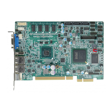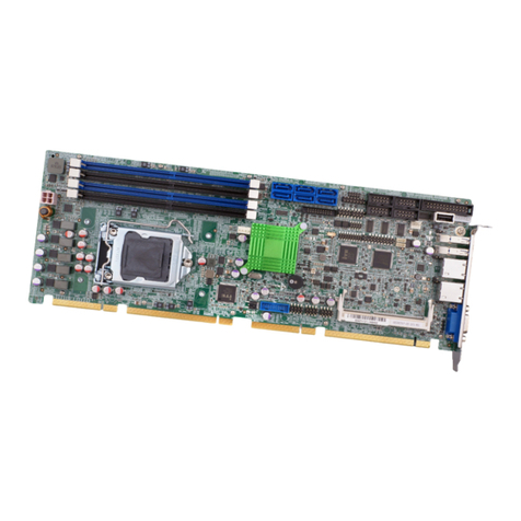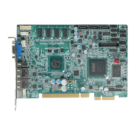
PCIE-Q350 PICMG 1.3 CPU Card
Page IX
2.9.1 System Monitoring ........................................................................................... 34
2.9.2 Operating Temperature and Temperature Control........................................... 34
2.9.3 Power Consumption......................................................................................... 35
2.10 EXPANSION OPTIONS.............................................................................................. 35
2.10.1 Expansion Options Overview......................................................................... 35
2.10.2 IEI Expansion PICMG 1.3 Backplanes ......................................................... 35
2.10.3 IEI Chassis..................................................................................................... 36
3 UNPACKING............................................................................................................... 39
3.1ANTI-STATIC PRECAUTIONS...................................................................................... 40
3.2 UNPACKING.............................................................................................................. 40
3.2.1 Unpacking Precautions.................................................................................... 40
3.3 UNPACKING CHECKLIST........................................................................................... 41
3.3.1 Package Contents............................................................................................. 41
3.4 OPTIONAL ITEMS...................................................................................................... 42
4 CONNECTOR PINOUTS........................................................................................... 44
4.1 PERIPHERAL INTERFACE CONNECTORS..................................................................... 45
4.1.1 PCIE-Q350 Layout .......................................................................................... 45
4.1.2 Peripheral Interface Connectors ..................................................................... 45
4.1.3 External Interface Panel Connectors............................................................... 46
4.2 INTERNAL PERIPHERAL CONNECTORS...................................................................... 47
4.2.1 ATX Power Connector ..................................................................................... 47
4.2.2 Audio Connector .............................................................................................. 48
4.2.3 Digital Input/Output (DIO) Connector............................................................ 49
4.2.4 Fan Connector, CPU (12V, 4-pin).................................................................... 50
4.2.5 Fan Connector, System (12V, 3-pin) ................................................................ 51
4.2.6 Front Panel Connector .................................................................................... 52
4.2.7 Infrared Interface Connector........................................................................... 54
4.2.8 Keyboard/Mouse Connector ............................................................................ 54
4.2.9 SATA Drive Connectors ................................................................................... 55
4.2.10 Serial Port Connector (COM1, COM 2)........................................................ 56
4.2.11 Trusted Platform Module (TPM) Connector.................................................. 57
4.2.12 SDVO Control Connector.............................................................................. 58
4.2.13 USB Connectors (Internal)............................................................................ 59
