IEI Technology ICE-9652 User manual

ICE-9652/9602 COM Express Basic Type 2 Module
Page i
IEI Technology Corp.
User Manual
ICE-9652/9602
MODEL:
ICE-9652/9602
MODEL:
COM Express Basic Type 2 Module
Intel® Core2Duo/Celeron® M Processor with
VGA/LVDS, GbE, SATA, USB and Audio
Rev. 1.00 – 5 March, 2009

ICE-9652/9602 COM Express Basic Type 2 Module
Page ii
Revision
Date Version
Changes
5 March, 2009 1.00 Initial release

ICE-9652/9602 COM Express Basic Type 2 Module
Page iii
Copyright
COPYRIGHT NOTICE
The information in this document is subject to change without prior notice in order to
improve reliability, design and function and does not represent a commitment on the part
of the manufacturer.
In no event will the manufacturer be liable for direct, indirect, special, incidental, or
consequential damages arising out of the use or inability to use the product or
documentation, even if advised of the possibility of such damages.
This document contains proprietary information protected by copyright. All rights are
reserved. No part of this manual may be reproduced by any mechanical, electronic, or
other means in any form without prior written permission of the manufacturer.
TRADEMARKS
All registered trademarks and product names mentioned herein are used for identification
purposes only and may be trademarks and/or registered trademarks of their respective
owners.

ICE-9652/9602 COM Express Basic Type 2 Module
Page iv
Table of Contents
1 INTRODUCTION.......................................................................................................... 1
1.1 INTRODUCTION........................................................................................................... 2
1.2APPLICATIONS ............................................................................................................ 2
1.3 BENEFITS ................................................................................................................... 3
1.4 FEATURES................................................................................................................... 3
1.5 OVERVIEW PICTURE ................................................................................................... 4
1.6 DIMENSIONS............................................................................................................... 6
1.6.1 Side Dimensions................................................................................................. 7
1.7 DATA FLOW................................................................................................................ 8
1.8 TECHNICAL SPECIFICATIONS ...................................................................................... 9
2 UNPACKING................................................................................................................11
2.1ANTI-STATIC PRECAUTIONS...................................................................................... 12
2.2 UNPACKING PRECAUTIONS....................................................................................... 12
2.3 PACKING LIST........................................................................................................... 13
3 CONNECTORS ........................................................................................................... 14
3.1 PERIPHERAL INTERFACE CONNECTORS..................................................................... 15
3.1.1 ICE-9652/9602 Layout..................................................................................... 15
3.1.2 Peripheral Interface Connectors ..................................................................... 16
3.2 INTERNAL PERIPHERAL CONNECTORS...................................................................... 16
3.2.1 COM Express Connector AB ........................................................................... 16
3.2.2 COM Express Connector CD........................................................................... 21
3.2.3 SO-DIMM Connector....................................................................................... 25
3.2.4 SPI Flash Connector........................................................................................ 26
4 INSTALLATION ......................................................................................................... 27
4.1ANTI-STATIC PRECAUTIONS...................................................................................... 28
4.2 INSTALLATION CONSIDERATIONS.............................................................................. 28
4.3 SO-DIMM INSTALLATION ....................................................................................... 30
4.4 JUMPER SETTINGS .................................................................................................... 31

ICE-9652/9602 COM Express Basic Type 2 Module
Page v
4.4.1 BIOS Selection................................................................................................. 31
4.4.2 LVDS Panel Resolution.................................................................................... 32
4.4.3 PEG and SDVO Configuration........................................................................ 33
4.5 MOUNTING THE ICE-9652/9602 .............................................................................. 34
5 BIOS SETUP................................................................................................................ 37
5.1 INTRODUCTION......................................................................................................... 38
5.1.1 Starting Setup................................................................................................... 38
5.1.2 Using Setup...................................................................................................... 38
5.1.3 Getting Help..................................................................................................... 39
5.1.4 Unable to Reboot After Configuration Changes.............................................. 39
5.1.5 BIOS Menu Bar................................................................................................ 39
5.2 MAIN........................................................................................................................ 40
5.3ADVANCED............................................................................................................... 41
5.3.1 CPU Configuration.......................................................................................... 42
5.3.2 IDE Configuration........................................................................................... 43
5.3.2.1 IDE Master, IDE Slave ............................................................................. 44
5.3.3 Floppy Configuration....................................................................................... 49
5.3.4 Super IO Configuration ................................................................................... 50
5.3.5 Win83627EHG Hardware Health Configuration ............................................ 55
5.3.6 Win83L784G Hardware Health ....................................................................... 56
5.3.7 Power Configuration ....................................................................................... 58
5.3.7.1 ACPI Configuration .................................................................................. 58
5.3.7.2 APM Configuration................................................................................... 59
5.3.8 Remote Access Configuration.......................................................................... 62
5.3.9 USB Configuration........................................................................................... 65
5.4 PCI/PNP................................................................................................................... 66
5.5 BOOT........................................................................................................................ 69
5.5.1 Boot Settings Configuration............................................................................. 70
5.6 SECURITY................................................................................................................. 72
5.7 CHIPSET ................................................................................................................... 73
5.7.1 Northbridge Configuration.............................................................................. 74
5.7.1.1 Video Function Configuration .................................................................. 75
5.7.2 Southbridge Configuration .............................................................................. 76
5.8 EXIT......................................................................................................................... 77

ICE-9652/9602 COM Express Basic Type 2 Module
Page vi
6 SOFTWARE INSTALLATION.................................................................................. 79
6.1AVAILABLE SOFTWARE DRIVERS .............................................................................. 80
6.2 STARTING THE DRIVER PROGRAM ............................................................................ 80
6.3 CHIPSET DRIVER INSTALLATION............................................................................... 82
6.4 VGADRIVER INSTALLATION.................................................................................... 85
6.5 LAN DRIVER INSTALLATION.................................................................................... 89
6.6 REALTEK HDAUDIO DRIVER (ALC883) INSTALLATION.......................................... 94
6.6.1 BIOS Setup....................................................................................................... 95
6.6.2 Driver Installation ........................................................................................... 95
6.7 INTEL®MATRIX STORAGE MANAGER DRIVER INSTALLATION................................ 101
6.8 IDE CONTROLLER INSTALLATION .......................................................................... 105
6.9 ISMM INSTALLATION..............................................................................................115
A BIOS OPTIONS ........................................................................................................ 121
B TERMINOLOGY...................................................................................................... 125
C WATCHDOG TIMER .............................................................................................. 129
D COMPATIBILITY.................................................................................................... 132
D.1 COMPATIBLE OPERATING SYSTEMS ....................................................................... 133
D.2 COMPATIBLE PROCESSORS..................................................................................... 133
D.3 COMPATIBLE MEMORY MODULES ......................................................................... 134
E HAZARDOUS MATERIALS DISCLOSURE ....................................................... 135
E.1 HAZARDOUS MATERIALS DISCLOSURE TABLE FOR IPB PRODUCTS CERTIFIED AS
ROHS COMPLIANT UNDER 2002/95/EC WITHOUT MERCURY..................................... 136

ICE-9652/9602 COM Express Basic Type 2 Module
Page vii
List of Figures
Figure 1–1: ICE-9652/9602 with Heatspreader and Heatsink .....................................................2
Figure 1-2: ICE-9652/9602 Overview (Front Side)........................................................................4
Figure 1-3: ICE-9652/9602 Overview (Reverse Side)...................................................................5
Figure 1-4: Main Dimensions (mm)...............................................................................................6
Figure 1-5: Side Dimensions (mm) ...............................................................................................7
Figure 1-6: Data Flow Block Diagram...........................................................................................8
Figure 3-1: Connector and Jumper Locations (Front Side) .....................................................15
Figure 3-2: Connector and Jumper Locations...........................................................................15
Figure 3-3: COM Express Connector AB Location ...................................................................17
Figure 3-4: COM Express Connector CD Location ...................................................................21
Figure 3-5: SO-DIMM Connector Location.................................................................................25
Figure 3-6: SPI Flash Connector.................................................................................................26
Figure 4-1: SO-DIMM Installation................................................................................................30
Figure 4-2: BIOS Selection Switch Location..............................................................................32
Figure 4-3: LVDS Panel Resolution Selection Switch Location ..............................................33
Figure 4-4: PEG and SDVO Configuration Switch Location.....................................................34
Figure 4-5: ICE-9652/9602 Installation........................................................................................35
Figure 6-1: Start Up Screen .........................................................................................................81
Figure 6-2: Drivers........................................................................................................................81
Figure 6-3: Chipset Driver Installation Program........................................................................82
Figure 6-4: Chipset Driver Welcome Screen..............................................................................83
Figure 6-5: Chipset Driver License Agreement.........................................................................83
Figure 6-6: Chipset Driver Read Me File ....................................................................................84
Figure 6-7: Chipset Driver Installation Complete......................................................................85
Figure 6-8: Select the Operating System ...................................................................................86
Figure 6-9: GMA Driver ................................................................................................................86
Figure 6-10: GMA Driver Readme File........................................................................................87
Figure 6-11: GMA Driver File Extraction ....................................................................................87
Figure 6-12: GMA Driver Installation Welcome Screen ............................................................88
Figure 6-13: GMA Driver License Agreement............................................................................88

ICE-9652/9602 COM Express Basic Type 2 Module
Page viii
Figure 6-14: GMA Driver Installing Notice .................................................................................89
Figure 6-15: GMA Driver Installation Complete.........................................................................89
Figure 6-16: Access Windows Control Panel ............................................................................90
Figure 6-17: Double Click the System Icon................................................................................90
Figure 6-18: Click the Device Manager Button..........................................................................91
Figure 6-19: Device Manager List ...............................................................................................91
Figure 6-20: PCIe Controller Driver Installation Icon................................................................92
Figure 6-21: LAN Driver Welcome Screen .................................................................................92
Figure 6-22: Ready to Install........................................................................................................93
Figure 6-23: LAN Driver Installation ...........................................................................................94
Figure 6-24: LAN Driver Installation Complete..........................................................................94
Figure 6-25: Select the Audio CODEC........................................................................................96
Figure 6-26: Select the OS...........................................................................................................97
Figure 6-27: Select the OS Version.............................................................................................97
Figure 6-28: Locate the Setup Program Icon.............................................................................98
Figure 6-29: The InstallShield Wizard Starts .............................................................................98
Figure 6-30: Preparing Setup Screen .........................................................................................99
Figure 6-31: InstallShield Wizard Welcome Screen ..................................................................99
Figure 6-32: Audio Driver Software Configuration................................................................. 100
Figure 6-33: Installation Wizard Updates the System............................................................ 100
Figure 6-34: Restart the Computer .......................................................................................... 101
Figure 6-35: InstallShield Wizard Setup Screen..................................................................... 102
Figure 6-36: Matrix Storage Manager Setup Screen .............................................................. 102
Figure 6-37: Matrix Storage Manager Welcome Screen ........................................................ 103
Figure 6-38: Matrix Storage Manager Warning Screen.......................................................... 103
Figure 6-39: Matrix Storage Manager License Agreement.................................................... 104
Figure 6-40: Matrix Storage Manager Readme File................................................................ 104
Figure 6-41: Matrix Storage Manager Setup Complete.......................................................... 105
Figure 6-42: Access Windows Control Panel ......................................................................... 106
Figure 6-43: Double Click the System Icon............................................................................. 107
Figure 6-44: Click the Device Manager Button....................................................................... 108
Figure 6-45: Device Manager List ............................................................................................ 109
Figure 6-46: Hardware Update Wizard..................................................................................... 110
Figure 6-47: Automatic or Manual Installation ....................................................................... 111
Figure 6-48: Select Driver Location......................................................................................... 112
ICE-9652/9602 COM Express Basic Type 2 Module
Page ix
Figure 6-49: Select Driver Location......................................................................................... 113
Figure 6-50: Install From Disk..................................................................................................113
Figure 6-51: Locate File ............................................................................................................ 114
Figure 6-52: Install From Disk..................................................................................................114
Figure 6-53: iSMM Directory.....................................................................................................115
Figure 6-54: iSMM Installation File........................................................................................... 115
Figure 6-55: iSMM InstallShield Welcome Screen.................................................................. 116
Figure 6-56: iSMM License Agreement.................................................................................... 116
Figure 6-57: iSMM Customer Information............................................................................... 117
Figure 6-58: iSMM Setup Type ................................................................................................. 118
Figure 6-59: iSMM Installation Confirmation .......................................................................... 119
Figure 6-60: iSMM InstallShield Wizard Complete................................................................. 120
Figure 6-61: iSMM Restart Confirmation................................................................................. 120

ICE-9652/9602 COM Express Basic Type 2 Module
Page x
List of Tables
Table 1-1: Technical Specifications............................................................................................10
Table 2-1: Package List Contents...............................................................................................13
Table 3-1: ICE-9652/9602 Interface Connectors ........................................................................16
Table 3-2: COM Express Connector AB Pin Definitions...........................................................20
Table 3-3: COM Express Connector CD Pin Definitions...........................................................25
Table 3-4: SPI Flash Connector...................................................................................................26
Table 4-1: Jumpers.......................................................................................................................31
Table 4-2: BIOS Selection............................................................................................................31
Table 4-3: LVDS Panel Resolution..............................................................................................32
Table 4-4: PEG and SDVO Configuration...................................................................................33
Table 5-1: BIOS Navigation Keys................................................................................................39

ICE-9652/9602 COM Express Basic Type 2 Module
Page xi
BIOS Menus
BIOS Menu 1: Main.......................................................................................................................40
BIOS Menu 2: Advanced..............................................................................................................42
BIOS Menu 3: CPU Configuration...............................................................................................42
BIOS Menu 4: IDE Configuration.................................................................................................43
BIOS Menu 5: IDE Master and IDE Slave Configuration...........................................................45
BIOS Menu 6: IDE Master and IDE Slave Configuration...........................................................49
BIOS Menu 7: Super IO Configuration........................................................................................50
BIOS Menu 8: Hardware Health Configuration..........................................................................55
BIOS Menu 9: Hardware Health Configuration..........................................................................56
BIOS Menu 10:Power....................................................................................................................58
BIOS Menu 11: ACPI Configuration............................................................................................59
BIOS Menu 12: APM Configuration.............................................................................................60
BIOS Menu 13: Remote Access Configuration..........................................................................62
BIOS Menu 14: USB Configuration.............................................................................................65
BIOS Menu 15: PCI/PnP Configuration.......................................................................................67
BIOS Menu 16: Boot.....................................................................................................................69
BIOS Menu 17: Boot Settings Configuration.............................................................................70
BIOS Menu 18: Security...............................................................................................................72
BIOS Menu 19: Chipset................................................................................................................73
BIOS Menu 20:Northbridge Chipset Configuration...................................................................74
BIOS Menu 21:Northbridge Chipset Configuration...................................................................75
BIOS Menu 22:Southbridge Chipset Configuration..................................................................76
BIOS Menu 23:Exit........................................................................................................................77


ICE-9652/9602 COM Express Basic Type 2 Module
Page 1
Chapter
1
1 Introduction

ICE-9652/9602 COM Express Basic Type 2 Module
Page 2
1.1 Introduction
Figure 1–1: ICE-9652/9602 with Heatspreader and Heatsink
The ICE-9652/9602 COM Express Basic Type 2 module provides the main processing
chips and is connected to a compatible COM Express carrier board. The ICE-9652/9602 is
equipped with an Intel® Core™2 Duo/Celeron® M CPU, Intel® GME965/GLE960
Northbridge and Intel® ICH8M-E Southbridge and provides multiple modern serial I/O
options, while offering limited support for legacy I/Os. The COM Express standard allows
the COM Express carrier board to be designed, while leaving the choice of processor till
the later stages of design. The ICE-9652/9602 provides a low power option with the full
range of modern I/O options. The ICE-9652/9602 embedded module is designed for
flexible integration by system developers into customized platform devices.
1.2 Applications
The ICE-9652/9602 is designed to the COM Express carrier board standard for being
embedded in customized baseboards for flexible applications.

ICE-9652/9602 COM Express Basic Type 2 Module
Page 3
1.3 Benefits
Some of the ICE-9652/9602 embedded platform benefits include:
Low power, high performance
Easy integration into customized baseboards
Easy upgrading
Easy maintenance
Easy design compatibility
Low cost product development
1.4 Features
Some of the ICE-9652/9602 features are listed below:
Complies with PICMG COM Express specifications
Complies with RoHS
Embedded Intel® Core™2 Duo/Celeron® M CPU
Supports up to 4 GB of 400 MHz, 533 MHz or 667 MHz of DDR2 memory
Support for one high performance gigabit Ethernet (GbE) controller
Support three SATA II devices
Support for eight USB 2.0 ports
Support for one IDE device

ICE-9652/9602 COM Express Basic Type 2 Module
Page 5
Figure 1-3: ICE-9652/9602 Overview (Reverse Side)

ICE-9652/9602 COM Express Basic Type 2 Module
Page 6
1.6 Dimensions
The main dimensions of the ICE-9652/9602 are shown in the diagram below.
Length: 125 mm
Width: 95 mm
Figure 1-4: Main Dimensions (mm)

ICE-9652/9602 COM Express Basic Type 2 Module
Page 7
1.6.1 Side Dimensions
The figure below shows the dimensions as viewed from the side.
Figure 1-5: Side Dimensions (mm)
This manual suits for next models
1
Table of contents
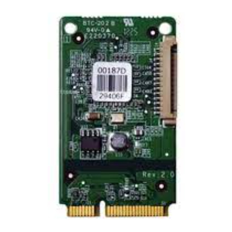
Other IEI Technology Control Unit manuals

IEI Technology
IEI Technology PulM Series User manual

IEI Technology
IEI Technology PCI-4S-RS-R40 User manual

IEI Technology
IEI Technology IVC-168G User manual

IEI Technology
IEI Technology MPCIE-UART-KIT01 User manual

IEI Technology
IEI Technology PCI-13SD-RS-R40 User manual

IEI Technology
IEI Technology AC-KIT-888HD User manual

IEI Technology
IEI Technology MPCIE-LAN-R10 User manual

IEI Technology
IEI Technology PulM-10G4T AQC107 User manual

IEI Technology
IEI Technology PulM-10G4SF-XL710 User manual

IEI Technology
IEI Technology PulM Series User manual