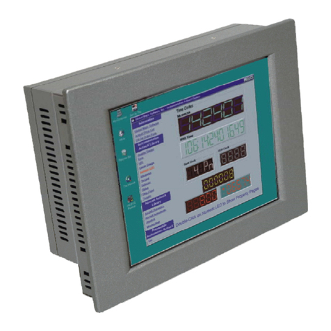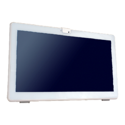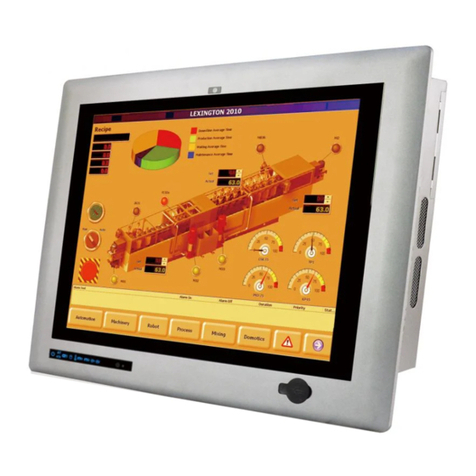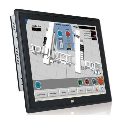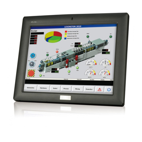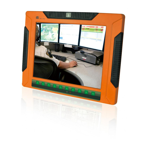
PPC-F12B/15B/17B/19B-BTi Panel PC
5.3.1 F81866 Super IO Configuration ...................................................................... 68
5.3.1.1 Serial Port n Configuration ....................................................................... 69
5.3.2 iWDD H/W Monitor ......................................................................................... 72
5.3.3 RTC Wake Settings ........................................................................................... 73
5.3.4 Serial Port Console Redirection ...................................................................... 74
5.3.4.1 Console Redirection Settings.................................................................... 75
5.3.5 iEi Feature ....................................................................................................... 78
5.3.6 CPU Configuration.......................................................................................... 79
5.3.7 IDE Configuration ........................................................................................... 81
5.3.8 USB Configuration........................................................................................... 82
5.4 CHIPSET ................................................................................................................... 83
5.4.1 North Bridge .................................................................................................... 84
5.4.1.1 Intel IGD Configuration............................................................................ 84
5.4.2 South Bridge..................................................................................................... 86
5.4.2.1 PCI Express Configuration ....................................................................... 88
5.5 SECURITY ................................................................................................................. 89
5.6 BOOT........................................................................................................................ 90
5.7 SAV E &EXIT ............................................................................................................ 92
5.8 SERVER MGMT ......................................................................................................... 94
5.8.1 System Event Log ............................................................................................. 95
5.8.2 BMC Network Configuration........................................................................... 96
6 INTERFACE CONNECTORS ................................................................................... 98
6.1 PERIPHERAL INTERFACE CONNECTORS..................................................................... 99
6.2 INTERNAL PERIPHERAL CONNECTORS .................................................................... 100
6.2.1 Audio Connector (AUDIO1) .......................................................................... 102
6.2.2 Chassis Intrusion Connector (CHASSIS1)..................................................... 102
6.2.3 Debug Port (DBG_PORT1)........................................................................... 102
6.2.4 DIO Connector (DIO1).................................................................................. 103
6.2.5 EC Debug Port (CN2).................................................................................... 103
6.2.6 Fan Connector (CPU_FAN1)......................................................................... 104
6.2.7 Front Panel Connector (F_PANEL1)............................................................. 104
6.2.8 I2C Connector (I2C1)..................................................................................... 104
6.2.9 IPMI Active LED Connector (LEDCN1) ....................................................... 105
6.2.10 Keyboard and Mouse Connector (KB_MS1) ............................................... 105
