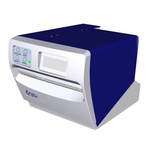
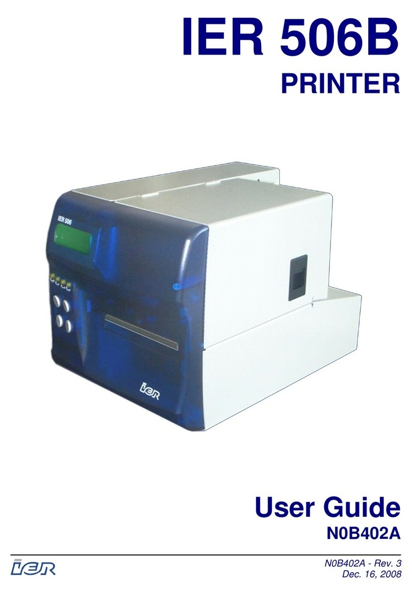
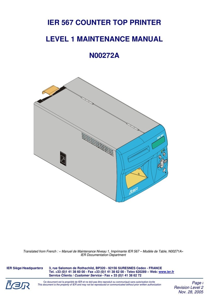
Ier 506 User manual

IER 506
PRINTER
N06802A
Revision Level 4
Feb. 20, 2006
USER GUIDE

2
NOTICE
This IER product comes with a lithium battery. Battery replacement must
imperatively be performed by qualified maintenance personnel. Moreover, only
IER approved models may be used.
CAUTION
DANGER OF EXPLOSION IF BATTERY IS INCORRECTLY REPLACED.
REPLACE ONLY WITH THE SAME OR EQUIVALENT TYPE
RECOMMENDED BY THE MANUFACTURER.
DISPOSE OF USED BATTERIES ACCORDING TO THE
MANUFACTURER’S INSTRUCTIONS
FCC (Federal Communications Commission) Statement
The United States Federal Communications Commission (in 47 CFR 15.105) has
specified that the following notice be brought to the attention of users of this product.
This equipment has been tested and found to comply with the limits for a Class A digital
device, pursuant to part 15 of FCC Rules. These limits are designed to provide
reasonable protection against harmful interference when the equipment is operated in a
commercial environment. This equipment generates, uses, and can radiate radio
frequency energy and, if not installed and used in accordance with the instruction
manual, may cause harmful interference to radio communications. Operation of this
equipment in a residential area is likely to cause harmful interference in which case the
user will be required to correct the interference at his own expense.
Use of a shielded cable is required to comply within Class A limits of Part 15 of FCC
Rules.
Pursuant to Part 15.21 of the FCC Rules, any changes or modifications to this
equipment not expressly approved by IER may cause harmful interference and void the
FCC authorization to operate this equipment.
NORWAY: This product is also designed for IT power distribution system with
phase-to-phase voltage 230V.
NORWAY & SWEDEN: Apparaten skall anslutas till jordat uttag när den
ansluts till ett nätverk.
THIS APPLIANCE MUST BE GROUNDED.
The cover is intended for occasional use and must be normally closed.
This product must exclusively be connected to an electrical circuit provided with
a ground fault circuit interrupter (GFCI) and complying with IEC 364 regulations.
The warranty shall be null and void in case of use of any spare part, special tool
or consumable part not expressly approved in writing by IER and in the event of
attempted repair or servicing of the machines by persons lacking the requisite
technical qualifications.
The information and specifications contained in this document are subject to change
without prior notice.
Translated from French: “Guide Utilisateur de l’Imprimante IER 506, N06801A, ind. 3”
IER Documentation Department

3
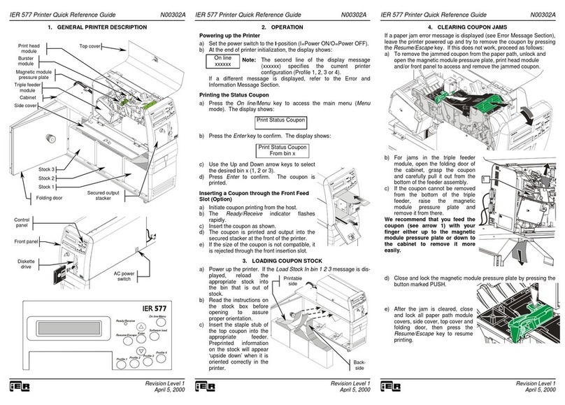
Table of Contents
A INTRODUCTION .............................................................................................. 4
B CONTENTS OF THE SHIPPING CONTAINER............................................... 6
C DESCRIPTION ................................................................................................. 7
1) Physical Characteristics........................................................................................... 7
2) Front View................................................................................................................ 9
3) Rear View .............................................................................................................. 10
4) Opening the Right Side Door ................................................................................. 11
5) Interior View........................................................................................................... 12
D INSTALLATION ............................................................................................. 13
1) Setting Up the Printer ............................................................................................ 13
2) Connecting the Printer to the Host......................................................................... 13
3) Connecting the Printer to the AC Power - Power-Up ............................................. 14
4) Adjusting the Paper Path ....................................................................................... 16
5) Loading Fanfold Media .......................................................................................... 18
6) Loading Roll Media ................................................................................................ 20
E OPERATION .................................................................................................. 23
1) Printing a Document .............................................................................................. 23
2) Removing Blank Media from the Printer Interior .................................................... 24
3) Key, LED Indicator and Sound Alarm Functions.................................................... 25
4) Self-Test Mode ...................................................................................................... 27
5) Printing the Configuration Test Document ............................................................. 27
6) Printing Other Test Documents.............................................................................. 27
F PERIODIC MAINTENANCE........................................................................... 29
1) Removing Dust from the Printer Interior................................................................. 29
2) Setting the Printhead to the Cleaning Position....................................................... 31
3) Cleaning the Platen and the Printhead .................................................................. 32
4) Final Check............................................................................................................ 33
G OPERATING FAULTS ................................................................................... 34
1) Clearing a Media Jam............................................................................................ 34
2) Clearing a Media Jam on Printers with Motorized Stacker..................................... 36
3) List of Error Messages........................................................................................... 37
4) Other Operating Problems ..................................................................................... 39
H CLEANING SUPPLIES AND TECHNICAL DOCUMENTATION .................. 40
1) List of the Cleaning Supplies ................................................................................. 40
2) Technical Documentation ...................................................................................... 40

4
A INTRODUCTION
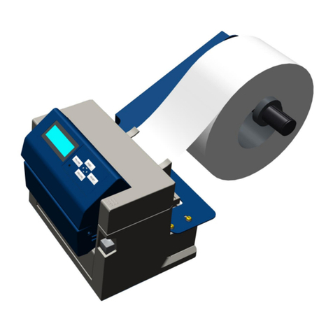
The IER 506 Counter Top Printer is primarily designed to print bag tags
and ATB1 type flight coupons in an airport check-in environment.
The print technology used by this printer is the direct thermal method
requiring the use of heat-sensitive media.
The IER 506 Printer accepts fanfold media (see Fig. 1 and Fig. 4) and
roll media (see Fig. 2 and Fig. 3) for bag tag and ATB1 flight coupon
printing.
The continuous blank media is inserted through the rear feed slot.
An optional 13.56 MHz or 900 MHz RFID (Radio Frequency
Identification) Reader can be added to the printer.
In addition, the printer can be fitted with one of the following three
optional media separation modules:
•Tear-Off module provided with a serrated tear strip
•Motorized Burster module coming with a burster blade
•Motorized Cutter module provided with a cutter blade
With its dimensions and design, the IER 506 Printer harmoniously blends
in with the IER 567 ATB printer series.
The IER 506 Printer models featuring a motorized document separator,
can be provided with a motorized stacker (see Fig. 4).
IMPORTANT:
A
For the basic IER 506 Printer model, which does not include
a coupon separator, the media must be provided with
p
erforations between the individual documents.
PLEASE NOTE: The motorized stacker cannot be used for
bag tags. It accommodates exclusively fanfold ATB
coupons.

5
Fig. 1
Fig. 2 Fig. 3
Fig. 4

6
B CONTENTS OF THE SHIPPING CONTAINER
In the box you will find the following:
•IER 506 Printer (1)
•IER 506 Printer User Guide (2) (present document)
•Test documents (3), one of which being the printout of the IER 506
Printer configuration
•AC power cord (4)
NOTE:
IMPRIMANTE
IER 506
Fig. 5
The IER 506 Printer is shipped without media or cleaning supplies
(see Page 40).
We recommend that you save the packing material at leas
t
throu
g
hout the warrant
y
p
eriod.
1
2
34
B

7
C DESCRIPTION
1) Physical Characteristics
Overall printer dimensions, cover open, without roll media shaft:
•Depth (A) 300 mm (11.8 in)
•Height (cover open) (B) 368 mm (14.5 in) approx.
•Width (cover open) (C) 300mm (11.8 in) approx.
Fig. 6
A
C
B
C

8
Overall printer dimensions with the covers closed and the media
shaft installed:
•Depth (A) 500 mm (19.69in)
•Height (B) 226 mm (8.9 in) (feet included)
•Width (C) 200 mm (7.87 in)
Weight:
•Without any options 7 kg (15.4 lbs.), approx.
•All options included <8 kg (<17.6 lbs.)
Operating temperature:
•+5°C (41°F) to +40°C (104°F)
Relative humidity, consumables excluded:
•20% to 80%, non-condensing
Fig. 7
A
C
B

9
2) Front View
•Front panel (1) (see Paragraph E3) including the following:
Four-line, 20-character per line alphanumeric Liquid Crystal
Display (LCD) (2)
Four LED indicators (3)
Four keys (4)
Ejection slot (5)
•Hinged right side door (6), fitted with a latch (7), giving access to
the printer interior (paper path, thermal printhead module)
Fig. 8
4
1
6
3
7
5
2

10
3) Rear View
•Electronics cover (1) with the following elements on the rear
panel of the electronics compartment:
AC line power connector (2)
AC power switch (3)
Data I/O, 25-contact female connector (4)
•Media insertion slot (5) made up of two adjustable paper guides
•Printhead lever (6).
•Printer identification plate located underneath the printer.
Fig. 9
5
1
3
5
2
6
4

11
4) Opening the Right Side Door
To open the right side door (1), simply proceed as follows:
•Push latch (2) upward.
•Swing the right side door (1) open and fold it onto the printer top.
Fig. 10
1
1
2

12
5) Interior View
Opening the right side door gives access to the following elements
located on the paper path side of the printer and allows the operator
to carry out basic operations regarding these elements (described in
the present document):
•Printhead (1) on its retractable mounting
•Platen (2)
•Knob to clear paper jams (3)
•Two paper guides (4) making up the adjustable paper path.
Fig. 11
1
2
4
4
3

13
D INSTALLATION
1) Setting Up the Printer
a) Remove the printer from the shipping container.
b) Place it on an even and stable surface providing enough
clearance so you can fully open the covers.
2) Connecting the Printer to the Host
IMPORTANT:
a) Make sure the printer is switched off by checking that the AC
power switch at the rear of the printer is set to the 0-position.
b) Connect and secure the data I/O cable to the corresponding
connector located at the rear of the printer.
Fig. 12
Fig. 13
To connect the printer to the host, it is essential to use a
shielded cable fitted with metal plated connector hoods. The
cable shield must be linked to these hoods.
D

14
3) Connecting the Printer to the AC Power - Power-Up
a) Make sure the printer is switched off by checking that the AC
power switch at the rear of the printer is set to the 0-position.
b) Connect the AC power cord first to the AC power connector
located at the rear of the printer, then to the line power outlet.
NOTE:
Fig. 14
Fig. 15
The printer power supply unit is autoranging and selects
automaticall
y
the line volta
g
e in use.

15
c) Power up the printer by setting the power switch to the I-position.
d) The display lights up. After 9 to 10 seconds, approximately, one
of the following two messages appears:
IER 506
OFF LINE MODE
if the printer is off line, or:
IER 506
ON LINE MODE
NOTE:
e) Adjust the paper path to the width of the media used (see Page
16).
f) Load media stock (see Pages 18 and 20).
Fig. 16
If an error message is displayed instead, refer to Page 37 to solve
the problem.

16
4) Adjusting the Paper Path
Before using the printer for the first time and when changing the
media width, you need to adjust the paper path.
IMPORTANT:
a) Open the right side door (see Page 11).
b) Locate the paper path locking wheel underneath the paper
guides. Loosen the wheel with your forefinger.
c) Adjust the paper path to the width of the media you are planning
to use. Insert the media all the way into the paper path.
Fig. 17
Fig. 18
Loosen the paper path locking wheel before attempting to
chan
g
e the paper path width. Also, be sure the AC powe
r
switch is set to the 0-
p
osition.

17
d) Fine-adjust the paper path width while leaving enough play (J,
see Figure below) to ensure that paper feed is smooth and
accurate at the same time
e) Tighten the paper path locking wheel.
f) Close the right side door.
IMPORTANT:
Fig. 19
Fig. 20
To avoid a possible paper jam, check that the media runs
freely along the paper path.
J
J

18
5) Loading Fanfold Media
Fanfold media loading can be performed in the following two ways:
a) Preliminary Steps:
•Install a box of fanfold media (3) at the rear of the printer. The
box must be placed parallel to the printer. Orient the box so
that the media, when inserted into the printer, has its heat-
sensitive side facing up.
•Switch on the printer (see Page 14).
b) Automatic Media Loading:
•Insert the leading document (1) of the stock into the insertion
slot (2). It will be drawn in automatically.
•The document is automatically ejected after some possible
back and forth movements, which correspond to the
separation mark self-calibration phase.
c) Manual Media Loading (Requires Lifting of the Printhead):
•Push the printhead lever (4) up.
•Insert the leading document (1) of the stock into the insertion
slot (2). Push it in until it protrudes from the ejection slot.
•Lower the printhead lever (4). The document is automatically
ejected, after some possible back and forth movements,
which correspond to the separation mark self-calibration
phase.
IMPORTANT:
Should media insertion into the rear feed slot be difficult,
p
erform the paper path ad
j
ustment a
g
ain
(
see Pa
g
e 16). Also
check that the media stock (box (3)) is correctly aligned with
the paper path. If media feeds unevenl
y
, move the bo
x
further awa
y
from the insertion slot.

19
Fig. 21
2
1
4
3

20
6) Loading Roll Media
a) Preliminary Steps (Roll Media Shaft with Removable
Flange):
Refer to the Figure of Page 21.
•Remove flange (1) from shaft (2).
•When installing the media roll (3) on shaft (2), make sure that
the heat-sensitive side (4) of the leading document will be
facing up when inserted into the printer.
•Slide the core of roll (3) onto the hubs (5). Power up the
printer (see Page 14).
b) Preliminary Steps (Roll Media Shaft with Retaining Pin):
•Slide the core of roll (3) onto the roll media shaft (8) while
making sure that the heat-sensitive side (4) of the leading
document will be facing up when inserted into the printer (see
Page 22).
c) Automatic Media Loading:
•Insert the leading document of the roll media into the insertion
slot (7) (see Page 21). It will be drawn in automatically.
•The document is automatically ejected, after some possible
forth and back movements, which correspond to the
separation mark self-calibration phase. Install flange (1) by
setting it against roll (3).
d) Manual Media Loading (Requires Lifting of the Printhead):
•Push the printhead lever (6) up and insert the leading
document (4) of the roll media into the insertion slot (7). Push
it in until it protrudes from the ejection slot.
•Lower the printhead lever (6). The document is automatically
ejected, after some possible back and forth movements,
which correspond to the separation mark self-calibration
phase.
•Install flange (1) by setting it against roll (3).
IMPORTANT:
Should media insertion into the rear feed slot be difficult,
p
erform the paper path ad
j
ustment a
g
ain
(
see Pa
g
e 16). Also
check that the roll is correctl
y
ali
g
ned with the paper path. I
f
not, perform media roll position adjustments.
Table of contents
Other Ier Printer manuals
