Ier 520 User manual

IER 520
PRINTER
N06902 A
Revision Level 3
Sept. 10, 1998
1
n06902a3.chp
Tue Sep 22 15:02:08 1998
Profil couleur : DØsactivØ(e)
Composite Ecran par dØfaut

2
WARNING
This equipment generates, uses and can radiate
radiofrequency energy and, if not installed and used in
accordance with the operator’s and the user’s manuals
may cause interference with radio communications. It
has been tested and found to comply with the limits for
a class “A” computing device, pursuant to subparagraph
“J”ofpart15ofFCCrules,whicharedesignedtoprovide
reasonable protection against such interference when
operated in a commercial environment. Operations of
this equipment in a residential area is likely to cause
interference, in whichcase the user -athis own expense
- will be required to take whatever measures may be
required to correct interference.
The use of a braided shielded data cable is required to
meet the FCC class “A” limits.
THIS APPLIANCE MUST BE GROUNDED.
(FCC : Federal Communication Commission)
NOTICE
The information and specifications contained in this
document are subject to change without prior notice.
The warranty shall be null and void in case of use of
any spare part, special tool or consumable part not
expressly approved in writing by IER and in the event
of attempted repair or servicing of the machines by
persons lacking the requisite technical qualifications.
n06902a3.chp
Tue Sep 22 15:02:09 1998
Profil couleur : DØsactivØ(e)
Composite Ecran par dØfaut

TABLE OF CONTENTS
3
TABLE DES MATIERES
A ) INTRODUCTION . . . . . . . . . . . . . . . . . . . . . . . . . . . . . . . . . . . . . . 5
B ) DESCRIPTION . . . . . . . . . . . . . . . . . . . . . . . . . . . . . . . . . . . . . . . 6
1) Contents of the Shipping Container . . . . . . . . . . . . . . . . . . . . . 6
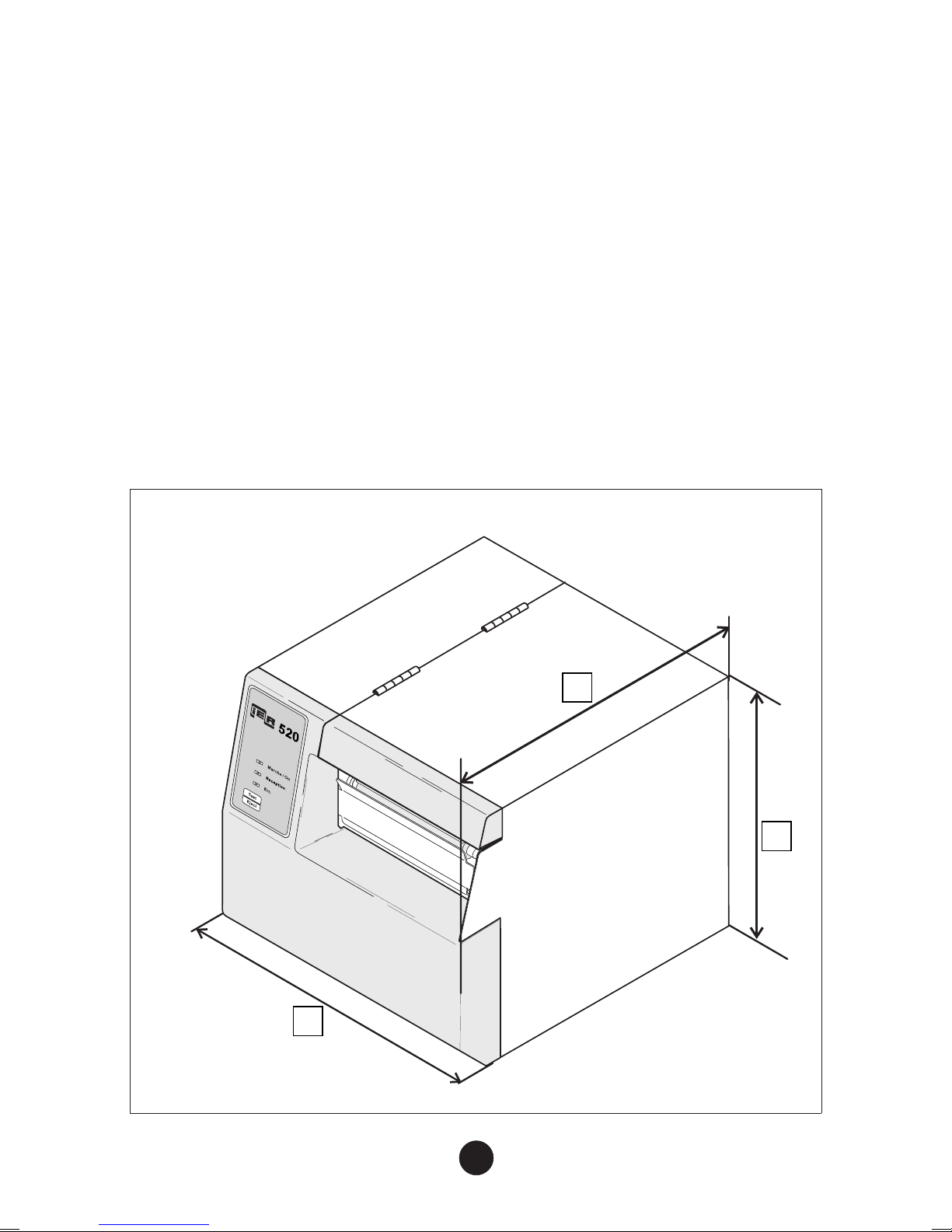
2) Physical Characteristics . . . . . . . . . . . . . . . . . . . . . . . . . . . . . . 7
3) Front View. . . . . . . . . . . . . . . . . . . . . . . . . . . . . . . . . . . . . . . . . 8
4) Rear View . . . . . . . . . . . . . . . . . . . . . . . . . . . . . . . . . . . . . . . . . 9
5) Interior View . . . . . . . . . . . . . . . . . . . . . . . . . . . . . . . . . . . . . . . 10
6) Options . . . . . . . . . . . . . . . . . . . . . . . . . . . . . . . . . . . . . . . . . . . 11
C ) INSTALLATION. . . . . . . . . . . . . . . . . . . . . . . . . . . . . . . . . . . . . . . 12
1) Setting Up the Printer . . . . . . . . . . . . . . . . . . . . . . . . . . . . . . . . 12
2) Connecting the Printer to the Host . . . . . . . . . . . . . . . . . . . . . . 12
3) Connecting the Printer to the Line Power/Power Up. . . . . . . . . 13
D ) INSTALLING THE SUPPLIES. . . . . . . . . . . . . . . . . . . . . . . . . . . . 14
1) Loading Roll Media . . . . . . . . . . . . . . . . . . . . . . . . . . . . . . . . . . 14
2) Installing Fanfold Stock. . . . . . . . . . . . . . . . . . . . . . . . . . . . . . . 16
E ) ADJUSTING THE PRINTER TO THE MEDIA USED . . . . . . . . . . 17
1) Adjusting the Paper Path Width . . . . . . . . . . . . . . . . . . . . . . . . 17
2) Adjusting the Media Sensor Position . . . . . . . . . . . . . . . . . . . . 18
3) Adjusting the Position of the Printhead Pressure Spring . . . . . 20
4) Adjusting the Printhead Pressure Thumbscrew . . . . . . . . . . . . 21
5) Media Loading . . . . . . . . . . . . . . . . . . . . . . . . . . . . . . . . . . . . . 22
F ) OPERATION . . . . . . . . . . . . . . . . . . . . . . . . . . . . . . . . . . . . . . . . . 26
1) Printing a Document . . . . . . . . . . . . . . . . . . . . . . . . . . . . . . . . . 26
2) Optional Features . . . . . . . . . . . . . . . . . . . . . . . . . . . . . . . . . . . 27
3) Key and Indicator Functions . . . . . . . . . . . . . . . . . . . . . . . . . . . 28
4) Test Mode. . . . . . . . . . . . . . . . . . . . . . . . . . . . . . . . . . . . . . . . . 30
5) Printing out the Configuration Test Document . . . . . . . . . . . . . 30
6) Printing the Print Quality Test Document . . . . . . . . . . . . . . . . . 31
n06902a3.chp
Tue Sep 22 15:02:09 1998
Profil couleur : DØsactivØ(e)
Composite Ecran par dØfaut

TABEL OF CONTENTS
4
G ) PERIODIC MAINTENANCE . . . . . . . . . . . . . . . . . . . . . . . . . . . . . 32
1) General . . . . . . . . . . . . . . . . . . . . . . . . . . . . . . . . . . . . . . . . . . . 32
2) General Printer Cleaning. . . . . . . . . . . . . . . . . . . . . . . . . . . . . . 32
3) Cleaning the Printhead and the Platen . . . . . . . . . . . . . . . . . . . 34
4) Final Check . . . . . . . . . . . . . . . . . . . . . . . . . . . . . . . . . . . . . . . . 35
H ) OPERATING FAULTS. . . . . . . . . . . . . . . . . . . . . . . . . . . . . . . . . . 36
1) Paper Out Condition . . . . . . . . . . . . . . . . . . . . . . . . . . . . . . . . . 36
2) Paper Jam. . . . . . . . . . . . . . . . . . . . . . . . . . . . . . . . . . . . . . . . . 36
3) Other Operating Problems . . . . . . . . . . . . . . . . . . . . . . . . . . . . 38
I ) CONSUMABLE SUPPLIES AND DOCUMENTATION . . . . . . . . . . . . . . . . 39
1) List of Consumable Supplies. . . . . . . . . . . . . . . . . . . . . . . . . . . 39
2) IER 520 Printer Technical Documentation . . . . . . . . . . . . . . . . 39
n06902a3.chp
Tue Sep 22 15:02:10 1998
Profil couleur : DØsactivØ(e)
Composite Ecran par dØfaut

AINTRODUCTION
The IER 520 Printer is designed for printing on self-adhesive labelsand
various other types of documents.
With its color and design, this compact but sturdy printer harmoniously
blends in with any industrial and modern office environment.
The host to which the IER 520 is connected controls all the printer
functions which makes its operation particularly user-friendly.
The IER 520 Printer relies on the direct thermal printing technology and
requires therefore the use of heat-sensitive media.
This printer can either be supplied with roll media (requires the roll
mediadispenseroption)orcontinuousfanfoldmedia.Inbothcases,the
media stock is located at the rear of the printer.
The IER 520 Printer exists in the following versions:
•IER 520 Printer with cutter option to separate the printed document
from the blank stock.
•IER 520 Printer with peel-off option, which rewinds the silicone
backingoftheadhesivelabelstoprovidethe operatorwithaprinted
document, ready to stick.
Mostofthecurrentcommunicationsinterfaces(RS232,RS422,RS485,
etc.) can be installed as an option to make the IER 520 truly universal.
A reflective sensor can be added to the printer in the event opaque
media is used which prevents operation of the transmissive sensor.
IMPORTANT The warning messages intended for the
operator are not listed in the present Guide as
they are specific to each customer application.
5
n06902a3.chp
Tue Sep 22 15:02:10 1998
Profil couleur : DØsactivØ(e)
Composite Ecran par dØfaut

BDESCRIPTION
1) Contents of the Shipping Container
The box contains the following:
•IER 520 Printer (1)
•User Guide (present document) (2)
•Bag containing the following:
•AC power supply cord (3)
•Test documents (4), one of which being the printout of the
printer configuration
NOTE The IER 520 Printer is shipped without consumable
supplies (media, cleaning kit, etc.)
We recommend that you save the packing material at
least throughout the warranty period.
6
IMPRIMANTE
IER 520
GUIDE D'UTILISATION
1
2
3
4
n06902a3.chp
Tue Sep 22 15:02:12 1998
Profil couleur : DØsactivØ(e)
Composite Ecran par dØfaut

2) Physical Characteristics
•Printer dimensions (without any options):
•Height (a): 224 mm (8.8 in) (feet included)
•Depth (b) (without media dispenser option): 264 mm (10.4 in)
•Width (c): 226 mm (8.9 in)
•Weight (without options, supplies, packing material): 8 kg (17.6lbs)
•Operating Temperature: + 5°C to + 40°C (41°F to 104°F)
•Relative humidity: 20 % to 80 % without condensation
7
a
b
c
n06902a3.chp
Tue Sep 22 15:02:12 1998
Profil couleur : DØsactivØ(e)
Composite Ecran par dØfaut

3) Front View
•Rightsidedoor(4).Togetaccesstotheprinterinterior,grabhandle
(3) and swing the right side door (4) up to its steady position.
•Control panel (1) with:
•one key and
•three indicators
•Document ejection slot (2).
8
14
23
n06902a3.chp
Tue Sep 22 15:02:13 1998
Profil couleur : DØsactivØ(e)
Composite Ecran par dØfaut

4) Rear View
•Insertion slot (1) for blank media feeding
•RS232C standard data I/O connector (2)
•AC power switch (3)
•AC line power connector (4)
•Printer identification plate (5)
9
+
+
+
+
+
+
+
4
2
3
1
5
n06902a3.chp
Tue Sep 22 15:02:14 1998
Profil couleur : DØsactivØ(e)
Composite Ecran par dØfaut

5) Interior View
The elements listed below are common to all IER 520 Printers:
•Printhead (1), printhead pressure thumbscrew (2), printhead
pressure spring (3), printhead latch (4)
•Paper guide shaft (5)
•Sliding collar (6)
•Media sensor translation shaft (7)
•Platen (8)
10
+
+
+
+
+
+
+
2
5
4
8
1
6
7
3
n06902a3.chp
Tue Sep 22 15:02:15 1998
Profil couleur : DØsactivØ(e)
Composite Ecran par dØfaut

6) Options
The following IER 520 Printer options are available:
•Cutter option (1) to separate the printed document from the stock.
•Peel-off option (2) which rewinds the silicone backing of the
self-adhesive labels and provides the operator with a label, ready
to stick.
NOTE The cutter and peel-off options cannot exist
simultaneously on an IER 520 Printer.
•Media low sensor option (3) to inform the operator that there is
enough media left to print one document.
11
+
+++
+
+
+
+
+
+
+
+
+
+
+
+
3
1
2
n06902a3.chp
Tue Sep 22 15:02:18 1998
Profil couleur : DØsactivØ(e)
Composite Ecran par dØfaut

CINSTALLATION
1) Setting Up the Printer
a) Remove the printer from the shipping container.
b) Place the printer on a stable surface.
2) Connecting the Printer to the Host
The printer to host data I/O connector is readily accessible at the rear
of the printer.
IMPORTANT To connect the printer to the host,it is essential
to use a shielded cable fitted with metal plated
connector hoods. The cable shield must be
attached to the connector hoods.
a) Make sure the AC power switch is set to the 0position.
b) PlugthedataI/Oconnectorintothestandardconnector(seeFigure
below) or into the specific connector if an optional interface is used.
12
n06902a3.chp
Tue Sep 22 15:02:18 1998
Profil couleur : DØsactivØ(e)
Composite Ecran par dØfaut

3) Connecting the Printer to the Line Power/Power Up
The AC power connector is readily accessible on the printer rear panel.
a) Make sure the AC power switch is in the 0position. Connect the
AC power cord first to the printer, then to the line power outlet.
NOTE The printer power supply unit is autoranging and
selects automatically the line voltage in use.
b) Power up the printer (set the power switch to the Iposition):
c) Check that the Marche/On indicator on the
control panel lights up.
d) The Err. indicator flashes during printer
initialization.
NOTE Shouldthe Err. indicator not gooutattheendofprinter
initialization (after 15 seconds, maximum), refer to
Page 36 to solve the problem encountered.
13
Err.
+
+
Marche / On
n06902a3.chp
Tue Sep 22 15:02:19 1998
Profil couleur : DØsactivØ(e)
Composite Ecran par dØfaut

DINSTALLING THE SUPPLIES
1) Loading Roll Media
If you are planning to use roll media, we recommend that the IER 520
Printer roll media dispenser option be installed to optimize media
feeding.
The vertical position of the dispenser shaft (1) must be adapted to the
diameter of the roll media core:
•Cores with small diameter: install the shaft in the lower position
•Cores with large diameter: install the shaft in the upper position
To change the position of shaft (1), remove it from the central mounting
plate by simply rotating it up and out of its seat, and installing it in its
new location.
14
1
Upper Position Lower Position
n06902a3.chp
Tue Sep 22 15:02:19 1998
Profil couleur : DØsactivØ(e)
Composite Ecran par dØfaut

a) Having correctly installed the media shaft, place the media roll (1)
on the shaft:
•Set the roll against the compartment side panel (direction of
black arrow).
•Set stop (2) against the cardboard core of the media roll
(direction of white arrow).
•When the roll is correctly positioned, close the right
compartment side door, making sure the roll does not hinder
the closing of the door.
b) Before proceeding with media loading, perform the various
adjustments described on the following Pages.
15
1
2
n06902a3.chp
Tue Sep 22 15:02:20 1998
Profil couleur : DØsactivØ(e)
Composite Ecran par dØfaut

2) Installing Fanfold Stock
Place the box containing the fanfold stock at the rear of the printer and
perform the following:
a) Place the box parallel to the printer.
b) Check that the heat-sensitive side of the media is facing up.
c) Before proceeding with media loading, perform the various
adjustments described on the following Pages.
16
+
+
+
+
+
+
Parallel
n06902a3.chp
Tue Sep 22 15:02:20 1998
Profil couleur : DØsactivØ(e)
Composite Ecran par dØfaut

EADJUSTING THE PRINTER TO THE
MEDIA USED
1) Adjusting the Paper Path Width
Before using the printer for the first time, or when changing the media
width, the paper path needs to be adjusted.
Open the right side door and proceed as follows:
a) Unlock theprinthead (see Page22). Slide collar (2) along the guide
shaft (1) towards the outside of the printer.
b) Feed the media strip into the printer (see Page 22). Do not lock
the printhead.
c) Set the media strip (4) against collar (3).
d) Slide collar (2) against the media strip.
IMPORTANT Collar (3) must always remain up against the
central mounting plate of the printer.
17
+
++
+
3
1
2
4
n06902a3.chp
Tue Sep 22 15:02:22 1998
Profil couleur : DØsactivØ(e)
Composite Ecran par dØfaut

2) Adjusting the Media Sensor Position
The media sensor must be correctly positioned to perform the following
two functions:
•Check the presence (or absence) of media under the printhead
•Sense the document positioning mark
The type of positioning mark depends on the document used and may
take the form of:
•a black mark
•a hole
•a translucent space between the labels (silicone label backing, i.e.
web)
IMPORTANT The IER 520 Printer media sensor is calibrated
to detect a particular type of positioning mark
(specified on the printout of printer
configuration, see Page 30). Changing the type
of positioning mark may lead to erroneous
printer operation, in which case the sensor will
need to be recalibrated (see IER 520 Printer
Maintenance Manual).
If you are using opaque media, the standard
(transmissive) media sensor must be replaced
by the optional reflective sensor.
18
n06902a3.chp
Tue Sep 22 15:02:22 1998
Profil couleur : DØsactivØ(e)
Composite Ecran par dØfaut

Open the right side door and adjust the media sensor position (see
following Page):
a) Feed some media (1) into the printer (see Page 22). Do not lock
the printhead.
b) Stand in front of the printer so you can see the triangular notch (2)
on the sensor support (3) which shows the exact position of the
sensor.
c) Move the sensor support (3) on shaft (4)until themedia sensor (i.e.
the triangular notch (2)) is located exactly above the positioning
mark when feeding the media.
NOTE If the positioning mark is the translucent space
between labels (web) which can be sensed over the
entire width of the media, position the sensor roughly
in the center.
19
520
Marche / On
3
1
24
n06902a3.chp
Tue Sep 22 15:02:23 1998
Profil couleur : DØsactivØ(e)
Composite Ecran par dØfaut

3) Adjusting the Position of the Printhead Pressure
Spring
In order to obtain aneven print contrast over the entire document width,
you need to adjust the printhead pressure according to the width of the
media used.
a) Open the right door.
b) Feed some media into the printer (see Page 22).
c) Orient the printhead spring (1) so that the center point of its front
edge is placed on the center line (2) of the media in the printer.
NOTE When one side of the print zone is darker, rotate the
printhead spring towards the opposite side for more
even print contrast.
20
2
1
n06902a3.chp
Tue Sep 22 15:02:23 1998
Profil couleur : DØsactivØ(e)
Composite Ecran par dØfaut
Table of contents
Other Ier Printer manuals
Popular Printer manuals by other brands

Printronix
Printronix SMARTLINE SL4M Programmer's reference manual

Lexmark
Lexmark 10Z0100 user guide

Star
Star TSP100III Series Hardware manual

Panasonic
Panasonic KX-P7100 Specifications

Epson
Epson Stylus Pro 7880 ColorBurst Edition - Stylus Pro 7880... user guide

Roland
Roland SOLJET PROIII XC-540 Setup guide