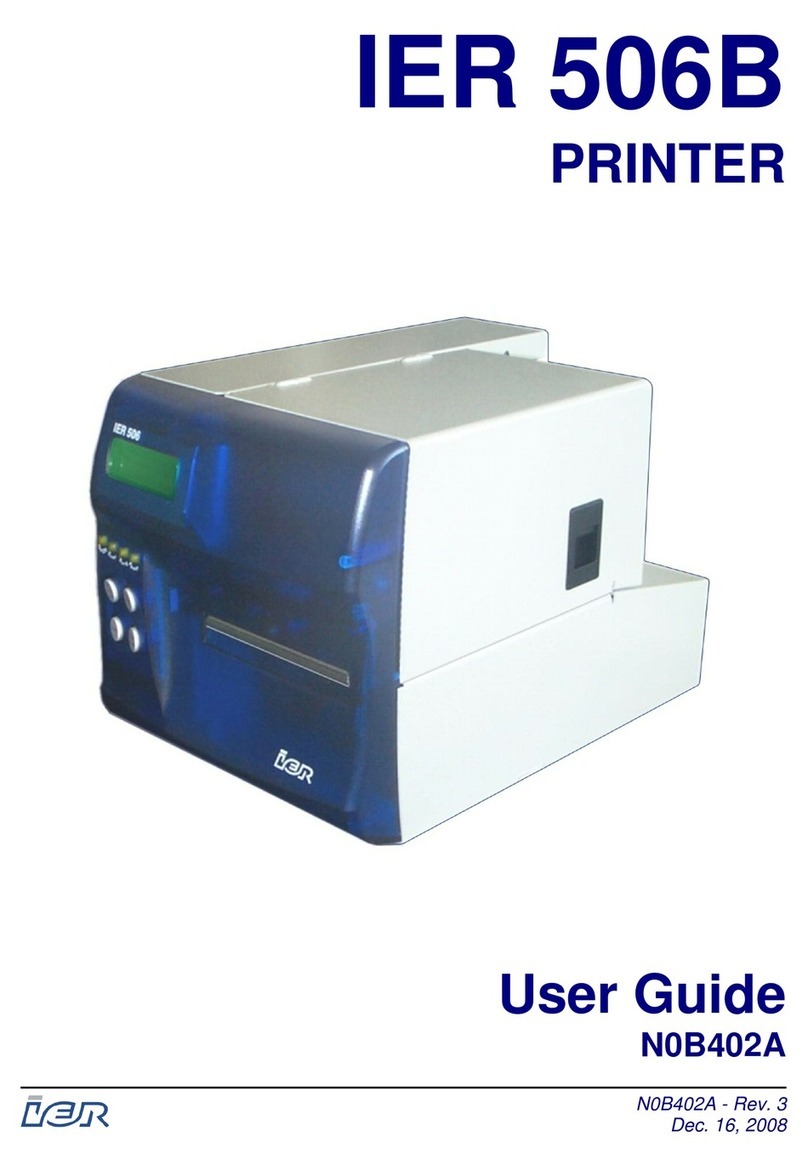
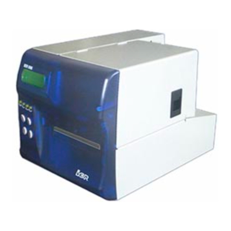
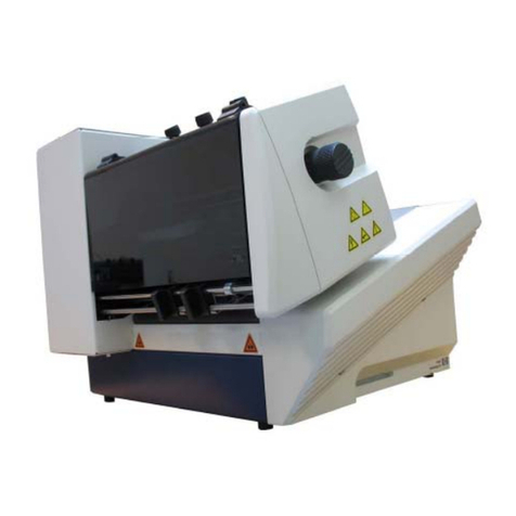
Ier 540 User manual

N06302A
Revision Level 3
Dec. 3, 2002
I
II
I
I
II
IE
EE
E
E
EE
ER
RR
R
R
RR
R
5
55
5
5
55
54
44
4
4
44
40
00
0
0
00
0
P
PP
P
P
PP
P
R
RR
R
R
RR
R
I
II
I
I
II
I
N
NN
N
N
NN
N
T
TT
T
T
TT
T
E
EE
E
E
EE
E
R
RR
R
R
RR
R

This page is intentionally blank.

3
NOTICE
This IER product comes with a lithium battery. Battery replacement must
imperatively be performed by qualified maintenance personnel. Moreover, only
IER approved models may be used.
CAUTION
DANGER OF EXPLOSION IF BATTERY IS INCORRECTLY REPLACED.
REPLACE ONLY WITH THE SAME OR EQUIVALENT TYPE
RECOMMENDED BY THE MANUFACTURER.
DISPOSE OF USED BATTERIES ACCORDING TO THE
MANUFACTURER’S INSTRUCTIONS
FCC (Federal Communications Commission) Statement
The United States Federal Communications Commission (in 47 CFR 15.105) has
specified that the following notice be brought to the attention of users of this product.
This equipment has been tested and found to comply with the limits for a Class A digital
device, pursuant to part 15 of FCC Rules. These limits are designed to provide
reasonable protection against harmful interference when the equipment is operated in a
commercial environment. This equipment generates, uses, and can radiate radio
frequency energy and, if not installed and used in accordance with the instruction
manual, may cause harmful interference to radio communications. Operation of this
equipment in a residential area is likely to cause harmful interference in which case the
user will be required to correct the interference at his own expense.
Use of a shielded cable is required to comply within Class A limits of Part 15 of FCC
Rules.
Pursuant to Part 15.21 of the FCC Rules, any changes or modifications to this
equipment not expressly approved by IER may cause harmful interference and void the
FCC authorization to operate this equipment.
NORWAY: This product is also designed for IT power distribution system with
phase-to-phase voltage 230V.
NORWAY & SWEDEN: Apparaten skall anslutas till jordat uttag när den ansluts till
ett nätverk.
THIS APPLIANCE MUST BE GROUNDED.
The cover is intended for occasional use and must be normally closed.
This product must exclusively be connected to an electrical circuit provided with
a ground fault circuit interrupter (GFCI) and complying with IEC 364 regulations.
The warranty shall be null and void in case of use of any spare part, special tool
or consumable part not expressly approved in writing by IER and in the event of
attempted repair or servicing of the machines by persons lacking the requisite
technical qualifications.
The information and specifications contained in this document are subject to change
without prior notice.
Translated from French: “Guide d’Utilisation de l’Imprimante IER 540, N06301A”
IER Documentation De
p
artment

4
T
TA
AB
BL
LE
E
O
OF
F
C
CO
ON
NT
TE
EN
NT
TS
S
A
A INTRODUCTION ...................................................................................6
B
B DESCRIPTION ......................................................................................7
1) CONTENTS OF THE SHIPPING CONTAINER...............................................7
2) PHYSICAL CHARACTERISTICS.................................................................8
3) FRONT VIEW .........................................................................................9
4) REAR VIEW .........................................................................................10
5) INTERIOR VIEW ...................................................................................11
C
C INSTALLATION...................................................................................12
1) SETTING UP THE PRINTER ...................................................................12
2) CONNECTING THE PRINTER TO THE HOST.............................................12
3) CONNECTING THE PRINTER TO THE LINE POWER/POWER UP................13
D INSTALLING THE SUPPLIES ............................................................14
1) INSTALLING ROLL MEDIA......................................................................14
2) INSTALLING FANFOLD STOCK ...............................................................14
E
E ADJUSTING THE PRINTER TO THE MEDIA USED .........................16
1) ADJUSTING THE PAPER PATH WIDTH ...................................................16
2) ADJUSTING THE MEDIA SENSOR ..........................................................18
3) ADJUSTING THE POSITION OF THE PRINTHEAD PRESSER.......................20
4) MEDIA LOADING ..................................................................................22
F
F CALIBRATING THE MEDIA SENSOR...............................................24
1) GENERAL............................................................................................24
2) CALIBRATING THE MEDIA SENSOR........................................................24
G
G OPERATION........................................................................................26
1) PRINTING A DOCUMENT .......................................................................26
2) COMMENTS ON THE CUTTER MODULE ..................................................27
3) KEY AND INDICATOR FUNCTIONS..........................................................28
4) TEST MODE ........................................................................................31
5) PRINTING THE CONFIGURATION TEST DOCUMENT.................................32
6) PRINTING THE TEST PATTERN DOCUMENT............................................33
7) PRINTING OUT THE RAMDISK CONTENTS ..............................................33

5
H
H PERIODIC MAINTENANCE................................................................34
1) GENERAL............................................................................................34
2) GENERAL PRINTER CLEANING..............................................................35
3) CLEANING THE PRINTHEAD AND THE PLATEN ........................................36
4) FINAL CHECK ......................................................................................38
I
I OPERATING FAULTS ........................................................................39
1) PAPER OUT CONDITION.......................................................................39
2) PAPER JAM.........................................................................................39
3) OTHER OPERATING PROBLEMS............................................................41
J
J SUPPLIES AND DOCUMENTATION .................................................42
1) LIST OF SUPPLIES ...............................................................................42
2) IER 540 PRINTER TECHNICAL DOCUMENTATION ..................................42

6
I
IN
NT
TR
RO
OD
DU
UC
CT
TI
IO
ON
N
The IER 540 Printer is designed for printing on self-adhesive labels
and various other types of media.
With its color and design, this compact but sturdy printer
harmoniously blends in with any industrial and modern office
environment.
IER 540 Printer operation is particularly user-friendly since all its
functions are host controlled.
The IER 540 Printer relies on the direct thermal printing technology
and requires therefore the use of heat-sensitive media.
Truly universal, this printer accepts most of the existing types of
continuous thermal media (rolls or fanfold stock featuring positioning
marks such as the translucent space between labels (web), holes,
black marks on the front side or back side of the media, etc.)
The IER 540 Printer can be equipped with a cutter, which separates
the printed documents from the stock.
To adapt the printer to your computer environment, various
communications interfaces are available: RS232, or USB (standard
versions) or the RS422 or parallel interface options.
IMPORTANT
The warning messages intended for the
operator are not listed in the present Guide,
as they are specific to each application
A
A

7
D
DE
ES
SC
CR
RI
IP
PT
TI
IO
ON
N
1) Contents of the Shipping Container
The box contains the following:
•IER 540 Printer (1)
•User Guide (2) (present document)
•Bag containing the following:
•AC power supply cord (3)
•Test documents (4), one of which being the printout of the
printer configuration
NOTE
The IER 540 Printer is shipped without supplies
(media, cleaning kit, etc.).
We recommend that you save the packing
material at least throughout the warranty period.
B
B
1
4
2
3

8
2) Physical Characteristics
•Printer dimensions (without any options):
•Height (a): 215 mm (8.46 in) (feet included)
•Depth (b): 340 mm (13.4 in)
•Width (c): 260 mm (10.2 in)
•Weight (without options, supplies, packing material): 9.5 kg
(20.95 lbs.)
•Operating temperature: +5°C to +40°C (41°F to 104°F)
•Relative humidity: 20 % to 80 %, without condensation
c
a
b

9
3) Front View
•Right side door (3). To get access to the printer interior, swing the
right side door (3) up to the steady position.
•Control panel (1) with:
•one key and
•three indicators
•Document ejection slot (2)
1
2
3

10
4) Rear View
•Insertion slot (1) to feed blank media from an external stock
•Additional slot (2) to install an optional communications interface
•Standard RS232C data I/O connector (3)
•AC power switch (4)
•AC line power connector (5)
•Printer identification plate (6)
3
5
4
6
12

11
5) Interior View
The elements listed below are common to all IER 540 Printers:
•Sliding media sensor (1)
•Paper guide shaft (2) with adjustable paper guide
•Printhead on retractable mounting (3)
•Platen (4)
•Printhead latch (5)
As an option, the IER 540 Printer can be equipped with a cutter (6).
1
2
3
4
56

12
I
IN
NS
ST
TA
AL
LL
LA
AT
TI
IO
ON
N
1) Setting Up the Printer
a) Remove the printer from the shipping container.
b) Place the printer on a stable work surface.
2) Connecting the Printer to the Host
The printer to host data I/O connector is readily accessible at the
rear of the printer.
IMPORTANT
To connect the printer to the host, it is
essential to use a shielded cable fitted with
metal plated connector hoods. The cable
shield must be attached to the connector
hoods.
a) Make sure the AC power switch is set to the 0-position.
b) Plug the data I/O connector into the corresponding connector at
the rear of the printer. Lock it.
C
C

13
3) Connecting the Printer to the Line Power/Power Up
The AC power connector is readily accessible on the printer rear
panel.
a) Make sure the AC power switch is in the 0-position. Connect the
AC power cord first to the printer, then to the line power outlet.
NOTE
The printer power supply unit is autoranging and
selects automatically the line voltage in use.
b) Power up the printer (set the power switch to the I-position):
c) Check that the Power indicator on the
control panel lights up. Power
The printer will be operational after the two-second initialization
sequence during which it is busy and cannot receive any data.

14
I
IN
NS
ST
TA
AL
LL
LI
IN
NG
G
T
TH
HE
E
S
SU
UP
PP
PL
LI
IE
ES
S
1) Installing Roll Media
If using roll media, you will have to install an adequate roll media
dispenser provided with a media supply hanger (shaft or hub) to
install the rolls, and a roll centering device. Make sure the installation
complies with the following requirements:
•The roll must be parallel to the printer.
•Viewed from the rear, the right edge of the media must be placed
15 mm (0.6 in) from the central mounting plate of the printer (see
Figure opposite).
2) Installing Fanfold Stock
Place the box containing the fanfold stock at the rear of the printer
and perform the following:
•Place the box parallel to the printer.
•Viewed from the rear, the right edge of the media must be placed
15 mm (0.6 in) from the central mounting plate of the printer (see
Figure opposite).
D
D

15
Parallel
Parallel
15 mm
(0.6 in)
15 mm
(0.6 in)

16
A
AD
DJ
JU
US
ST
TI
IN
NG
G
T
TH
HE
E
P
PR
RI
IN
NT
TE
ER
R
T
TO
O
T
TH
HE
E
M
ME
ED
DI
IA
A
U
US
SE
ED
D
1) Adjusting the Paper Path Width
Before using the printer for the first time, or when changing the
media width, the paper path needs to be adjusted. Proceed as
follows:
a) Open the right side door.
b) Proceed as follows to unlock the printhead:
•Actuate latch (2) in the direction shown by the arrow.
•The printhead (1) swings open automatically.
c) To adjust the paper path, proceed as follows:
STEP 1
•Slide the adjustable paper guide (4) on shaft (3) towards the
outside of the printer.
•Rotate guide (4) up.
STEP 2
•Feed some media (5) into the printer. Do not lock the
printhead.
STEP 3
•Set the media (5) against guide (6).
•Rotate guide (4) down and set it against the media.
E
E
1
2

17
IMPORTANT
Guide (6) must always remain up against the
central mounting plate of the printer.
3
4
5
STEP 1
STEP 2
STEP 3
6
5

18
2) Adjusting the Media Sensor
To synchronize media feeding with the other printer functions, the
media is provided with positioning marks. The type of positioning
mark depends on the document used and may take the form of:
•a black mark (on the front or back side of the document)
•a hole
•the translucent space (silicone backing, web) between the labels
a) Configuring the Sensor According to the Positioning Mark Used
IMPORTANT
In addition to the manual sensor
adjustments, it is necessary to configure the
printer at the software level according to the
type of positioning mark used (see Technical
Manual).
Media sensor settings depend on the type of positioning mark
used.
1) Pull on the sensor support until you have access to the
configuration DIP switches (1).
2) Refer to the Figure below to set the switches (1) according to
the type of positioning mark on the media
3) Perform now the media sensor position adjustments (see
following Section).
Switch
translucent space,
hole, no mark
black mark on front
side of document
black mark on back
side of document
11

19
b) Adjusting the Media Sensor Position
The media sensor must be correctly positioned to be able to
perform the following two functions:
•Check the presence (or absence) of media under the
printhead
•Sense the document positioning mark.
To adjust the position of the media sensor, proceed as follows:
1) Locate the pointer (2) on the sensor support (1) showing the
exact position of the sensor.
2) Move the sensor support and center the pointer (2) (and thus
the sensor) with regard to the positioning mark (4) on the
media (3).
NOTE
If the positioning mark is the translucent space
between labels (web) which can be sensed over the
entire width of the media, position the sensor
roughly in the center of the media.
Positioning mark:
translucent
space between
labels
Positioning mark:
hole
Positioning mark:
black mark
3 2 1
4

20
3) Adjusting the Position of the Printhead Presser
For optimum print contrast the printhead pressure needs to be
adjusted in accordance with the width of the media used.
a) Insert some media (2) into the printer and feed it beyond the
printhead.
b) Lower the printhead, but do not lock it.
c) Grasp the printhead presser at the front (1) and lift it up. Rotate it
so that the center point of its front edge is placed over the center
line (2) of the media (3) in the printer (use the guiding marks on
the printhead support).
NOTE
Should you notice a difference in the print contrast
(left vs. right side of the document), you will have
to take up the adjustment again.
1
1
2
1
32
Table of contents
Other Ier Printer manuals
