Ier 567 User manual

IER 567
PRINTER
IER
567
Print
er
User
Guid
e
N00202A
Revision Level 5
Jan. 22, 2009

2
NOTICE
!
DANGER
THIS IER PRODUCT COMES WITH A LITHIUM BATTERY.
BATTERY REPLACEMENT MUST IMPERATIVELY BE
PERFORMED BYQUALIFIED MAINTENANCE
PERSONNEL. MOREOVER, ONLY IER APPROVED
MODELS MAY BE USED.
!
DANGER
DANGER OF EXPLOSION IF BATTERY IS INCORRECTLY
REPLACED.
REPLACE ONLY WITH THE SAME OR EQUIVALENT TYPE
RECOMMENDED BY THE MANUFACTURER.
DISPOSE OF USED BATTERIES ACCORDING TO THE
MANUFACTURER’S INSTRUCTIONS
The United States Federal Communications Commission (in 47 CFR
15.105) has specified that the following notice be brought to the attention
of users of this product.
NOTE: This equipment has been tested and found to comply with the
limits for a Class B digital device, pursuant to Part 15 of the FCC Rules.
These limits are designed to provide reasonable protection against
harmful interference in a residential installation. This equipment
generates, uses and can radiate radio frequency energy and, if not
installed and used in accordance with the instructions, may cause
harmful interference to radio communications. However, there is no
guarantee that interference will not occur in a particular installation.
If this equipment does cause harmful interference to radio or television
reception, which can be determined by turning the equipment off and on,
the user is encouraged to try to correct the interference by one or more of
the following measures:
•Reorient or relocate the receiving antenna.
•Increase the separation between the equipment and
receiver.
•Connect the equipment into an outlet on a circuit different
from that to which the receiver is connected.
•Consult the dealer or an experienced radio/TV technician
for help.
Warning
Warning

3
In accordance with FCC requirements, changes or modifications not
expressly approved by IER could void the user's authority to operate this
product.
Use of a shielded cable is required to comply within Class B limits of Part 15
of FCC Rules.
NORWAY: This product is also designed for IT power distribution system
with phase-to-phase voltage 230V.
NORWAY & SWEDEN: Apparaten skall anslutas till jordat uttag när den
ansluts till ett nätverk.
!
DANGER
THIS APPLIANCE MUST BE GROUNDED.THIS PRODUCT
MUST EXCLUSIVELY BE CONNECTED TO AN ELECTRICAL
CIRCUIT THAT IS
•PROVIDED WITH A GROUND FAULT CIRCUIT
INTERRUPTER (GFCI) COMPLYING WITH IEC 364 AND
NFC15-100 REGULATIONS, AND
•CONFORMING WITH THE VOLTAGE CHARACTERISTICS
SPECIFIED BY THE NF EN 50160 STANDARD.
The cover(s), door(s) and/or drawer(s) of this product is (are) intended for
occasional use and must be normally closed.
The warranty shall be null and void in case of use of any spare part, special
tool or consumable not expressly approved in writing by IER and in the
event of attempted repair or servicing of the machines by persons lacking
the requisite technical qualifications.
This document contains proprietary information of IER. It may not be
reproduced or communicated without prior written authorization of IER. It is
intended solely for the use of the product described herein, to the exclusion
of any other usage.
It is provided as is, for information purposes only, without any warranty of
any kind, including any warranty of fitness or a particular purpose, and may
be modified by IER at any time.
The information and specifications contained in this document are subject to
change without prior notice.
Warning

4
Translated from French - IER Documentation Department
In compliance with the European Directive 2002/96/CE relative to the management of Waste Electrical and
Electronic Equipment (WEEE) implemented as of August 13, 2005, this product may not be disposed of
with regular household waste. All products concerned by this directive are marked with the above symbol.
The end owner of this product is responsible for either:
•Transferring the product to an authorized treatment facility where the product components,
recognized to present a hazard to the environment and/or public health, will be recycled and
recovered properly, or
•Consulting with the manufacturer for appropriate product waste management according to the
terms of the manufacturer.

5
TABLE OF CONTENTS
A INTRODUCTION ............................................................................................ 6
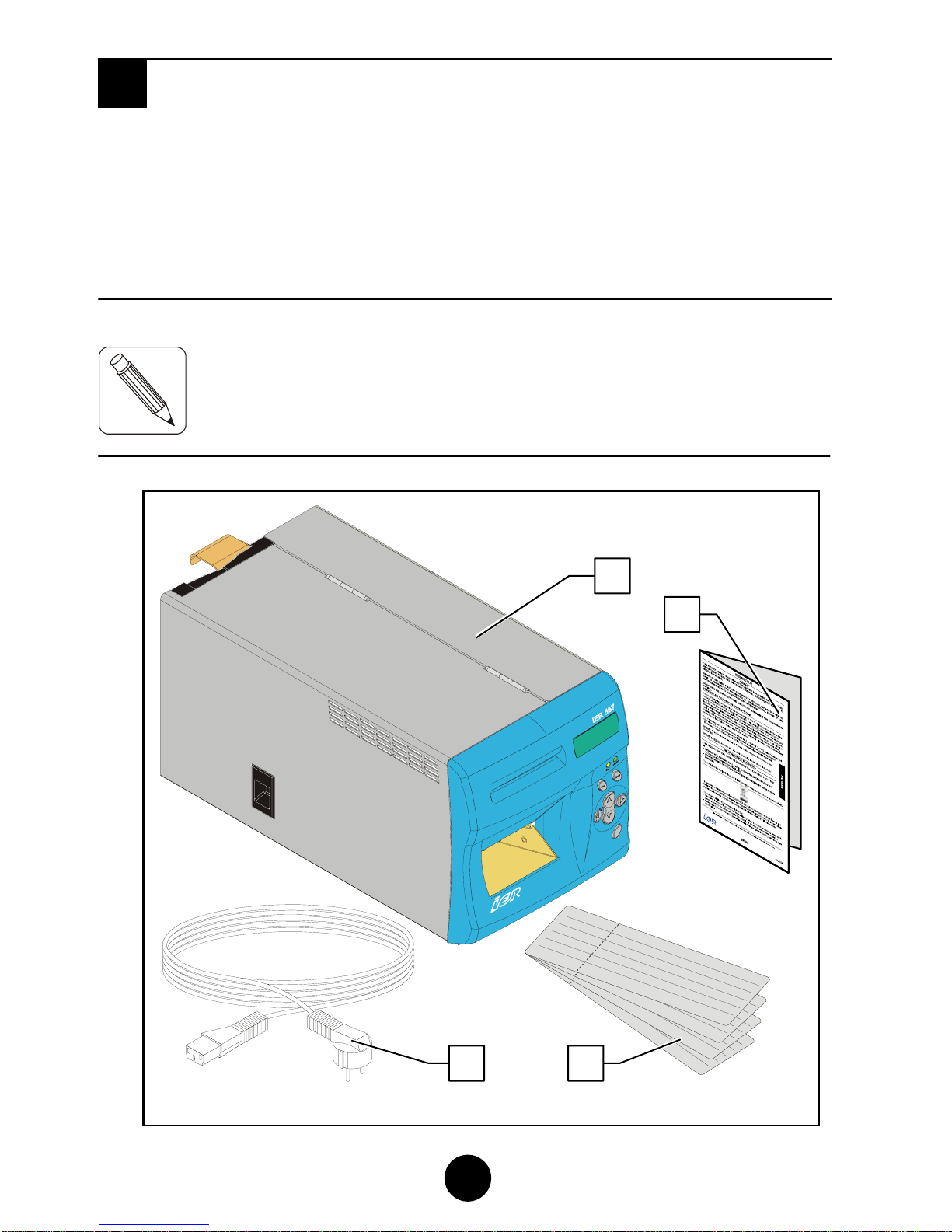
B CONTENTS OF THE SHIPPING CONTAINER............................................. 8
C DESCRIPTION ............................................................................................... 9
1) Physical Characteristics.........................................................................................9
2) Front Left View.....................................................................................................11
3) Rear Right View...................................................................................................12
4) Interior View – Paper Path...................................................................................13
5) Interior View – Paper Path (Thermal Transfer Option).........................................14
D INSTALLATION ........................................................................................... 15
1) Unpacking the Printer ..........................................................................................15
2) Connecting the Printer to the Host.......................................................................16
3) Connecting the Printer to the AC Line Power and Switching on the Printer.........16
4) Loading Blank Stock............................................................................................18
5) Installing the Multipass Ribbon Cartridge (Thermal Transfer Option) ..................21
E USING THE USER INTERFACE .................................................................22
1) Physical Layout of the User Interface..................................................................22
2) User Interface Key Functions...............................................................................23
3) User Interface Indicator and Sound Alarm Function............................................25
4) Coupon Printing...................................................................................................26
5) Printing the Status Coupon..................................................................................26
6) Inserting a Coupon through the Front Feed Slot (Option)....................................27
F PERIODIC MAINTENANCE.........................................................................28
1) General Printer Cleaning .....................................................................................28
2) Cleaning the Printhead and the Platen ................................................................30
3) Cleaning the Optional Magnetic Head .................................................................33
4) Final Checks........................................................................................................34
G OPERATING FAULTS.................................................................................35
1) List of Error Messages.........................................................................................35
2) Clearing a Paper Jam..........................................................................................37
3) Other Operating Faults ........................................................................................40
H CLEANING PRODUCTS AND TECHNICAL DOCUMENTATION..............41
1) List of Cleaning Products.....................................................................................41
2) IER 567 Printer Technical Documentation...........................................................41

6
A INTRODUCTION
The IER 567 Printer is designed to print ATB type travel documents.
Optionally, the printer can be enhanced with a magnetic module to
process data encoded on the magnetic stripe on the back of the ATB
documents.
The following two printing technologies are available for this printer:
•Direct thermal (standard equipment) to print on heat-sensitive media.
•Thermal transfer method (option). Printing is in this case achieved by
transferring melted ink dots from a ribbon contained in a cartridge to
the media.
Media is supplied:
•Continuously from the rear of the printer, via three feeders, two of
which are fitted as standard and the third is optional. (Fanfold stocks
of blank media can be placed either underneath the printer or inside a
cabinet on which the printer stands).
•Via the front feeder slot, when reading, revalidating or updating the
information on a coupon.
Another optional feature, the stock control number (SCN) reading
function, is available to prevent fraudulent use of blank stock.
The IER 567 Printer can be installed on top of a cabinet containing two or
three media stocks, which are accessed by opening a door or drawer.
With a two-door cabinet, the third stock can be set up outside the cabinet
on a foldaway stand.
The two or three internal stocks can be secured with key-locking catches.
A secure container (stacker) can be used if the printer is installed on top
of a cabinet.
A

7
Fig. 1
Fig. 2

8
B CONTENTS OF THE SHIPPING CONTAINER
In the box you will find the following elements:
•IER 567 Printer (1)
•User Safety Guide (2)
•Test coupons (3), one of which containing the IER 567 Printer
configuration
•AC line power cord (4).
NOTE:
Fig. 3
B
Visit our website to download the PDF version of the IER 56
7
Printer User Guide (www.ier.fr).
Blank coupons and cleaning products are not supplied with the
p
rinter (see Page 39).
We recommend that you save the packing material at leas
t
throughout the warranty period.
1
2
3
4

9
C DESCRIPTION
1) Physical Characteristics
Printer clearance with the covers open:
•Depth (A): 440 mm (17.32 in)
•Height (B): 434 mm (17.1 in)
•Width with operator access door open (C): 357 mm (14 in)
•Total width (D): 496 mm (19.53 in)
4
3
4 mm
437mm
357mm
496mm
Fig. 4
C
A
C
B
D

10
Overall printer dimensions with covers closed:
•Depth (A) 436.9 mm (17.21 in)
•Height (B) 201 mm (7.87 in) including feet
•Width (C) 200 mm. (7.87 in)
Weight:
•Without options: 10 Kg (22.05 lbs.)
•With thermal transfer option: 11 kg (24.26 lbs.).
Operating temperature:
•+5°C to +40°C (41°F to 104°F)
Relative humidity (non-condensing), consumables excluded:
•20% to 80%.
Fig. 5
A
C
B

11
2) Front Left View
a) Front panel (1) (cf. § E) where the following items are visible:
•Four-line, 20-character alphanumeric LCD display (2)
•Two indicators (3)
•Seven keys (4)
•Front feed slot (5)
•Output stacker (6) for printed coupons (7)
b) Hinged operator access door (8) fitted with a catch (9).
Fig. 6
8 1
7
6
3
5
4
9
2

12
3) Rear Right View
a) Electronics module (1) where the following items are visible:
•Rear:
♦AC line power connector (2)
♦25-pin female connector (3) for RS232 serial link to
computer system.
♦A mini-DIN connector (4) for a connection to a keyboard or
other optional peripherals compatible with the IER 567
printer (secure stacker or cabinet).
♦Free slot (5) for an optional USB connector, network
connector or RS232 serial connector.
•Front:
♦AC power switch (6).
b) Three rear feeders (7).
c) Rear deflector (8).
Fig. 7
2
6
1
3
7
5
4
8

13
4) Interior View – Paper Path
Opening the operator access door allows the user to perform simple
operations (described in this manual) on accessible parts of the
paper path, which include:
a) Rear feeder assembly flange (1) providing access to the triple
rear feeder
b) Magnetic module (2)
c) Cutter module (3) and hinged paper guide (4), which is opened
and closed with a locking catch (5)
d) Thermal printhead (6) and printhead lift cam (7)
e) Platen (8)
f) Reject bin (9) located below the front output stacker (10)
Fig. 8 9
1 8
6
4
5
2
7
10
3

14
5) Interior View – Paper Path (Thermal Transfer Option)
Printers with the optional thermal transfer system have a number of
additional components, as shown on the diagram below:
a) Two spindles (1) that hold the black multi-pass ribbon cartridge
b) Two pins (2) to facilitate cartridge positioning and centering on
the two spindles (1)
c) A stepper motor (3) (unwinding motor)
d) A freewheeling geared motor (4) (winding motor)
Fig. 9
3
1
4
2
2
1

15
D INSTALLATION
1) Unpacking the Printer
a) Remove the printer from the box.
b) Install the printer on an even and stable work surface allowing
sufficient clearance for fully opening the covers.
c) Remove the transport packing (1) from between the area behind
the printhead mount (2) and the printhead assembly (3).
Fig. 10
Fig. 11
D
1 3
2

16
2) Connecting the Printer to the Host
IMPORTANT:
a) Ensure that the AC power switch located on the
right of the printer is switched off by pressing O (off-
position).
b) Connect and lock the data cable I/O connector to
the matching connector on the rear of the printer.
3) Connecting the Printer to the AC Line Power and
Switching on the Printer
a) Make sure the AC power switch located on the right of the printer
is set to the O-position (off-position).
Fig. 12
Fig. 13
Fig. 14
To connect the printer to the host, it is essential to use a
shielded cable fitted with metal plated connector hoods. The
cable shield must be attached to the connector hoods.

17
b) Plug the AC power cable first to the
AC power connector located at the
rear of the printer and then to the AC
line power outlet.
c) Switch the printer on by setting the
power switch to the I-position.
NOTE:
d) The LCD comes on and displays automatically the following
messages in the order specified below:
PLEASE WAIT
(Connect ing Keypad)
567 Resident
.....
PrXXXXX YY / YY / YYYY
Fig. 15
Fig. 16
The IER 567 Printer power supply unit is autoranging and adapts
itself automatically to the current AC line power voltage.

18
Where the X’es stand for the program number and the Y’s for the
date of program design
567 READY
Bins 1 2 3 empty
e) Load blank stock into the printer (refer to §D4).
f) The following message will be displayed:
567 READY
Rev i s ion X.XX
Where the x’es stand for the program version
NOTE:
NOTE:
4) Loading Blank Stock
a) Place the box(es) of blank stock under the printer as shown in the
Figure on page 19. When setting up the printer and stocks,
observe the measurements shown in the Figure.
If the LCD displays an error message instead, refer to page 33 to
solve the problem encountered.
Other printer initialization messages may be displayed durin
g
p
rinter initialization, depending on the protocol configuration
(refer to the IER 567 Printer Technical Manual, IER P/
N
N00211A
)
.

19
b) Check that the printer is ready (the display should show 567
READY, Bins 1 2 3 empty).
Fig. 17
Stock1
Stock3
Stock2

20
c) Insert the leading coupon of the fanfold stock(s) into the
corresponding rear feeder(s) (note that the uppermost feed slot
corresponds to stock 1). When inserted, the coupon is
immediately and automatically drawn in.
NOTE:
*NOTE:
Fig. 18
Fig. 19
Fig. 20
If several stocks need to be loaded at the same time, we
recommend you start with the lowest feeder.
(1)Loading stock 2
(2) Loading stock 3
or stock 1*
A
label affixed to the rear of the
p
rinter indicates the positions o
f
stocks 1, 2 and 3.
(3) Loading stock 1
or stock 3*
Other manuals for 567
1
Table of contents
Other Ier Printer manuals