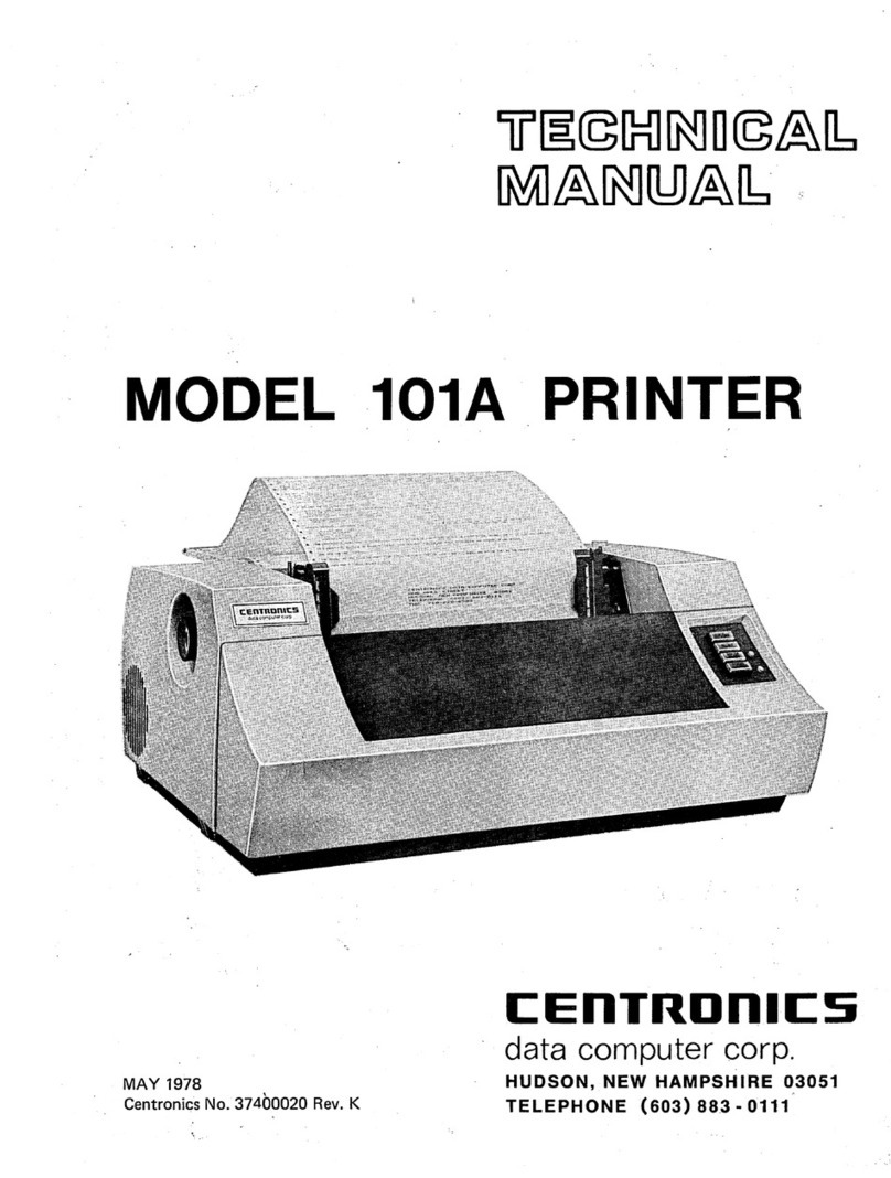
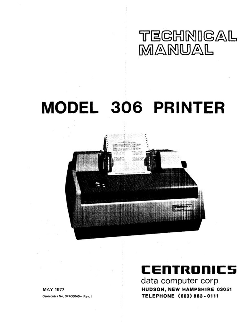
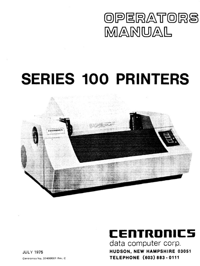
Centronics 705 User manual

TP 7·80
C:EnTRDnlCS
c:
E
nTRD
n I
cs
c:Fr
-~s
MODEL 705
C:I
PRINTER
-
·s
37400745
REV
C FEBRUARY
1982
C:~1111-<U111LS
C:EnTRDnlCS
C:EnTRDnlCS
.
C:EnTRDnlC:S
'
TECHNICAL MANUAL

THE
INFORMATION
CONTAINED HEREIN IS
PROPRIETARY
AND
IS
NOT
TO
BE
RELEASED
OR REPRODUCED WITHOUT WRITTEN
PER-
MISSION OF CENTRONICS data computer
corp.
SERVICING
INFORMATION
FOR YOUR PRINTER
MAY
BE
OBTAINED BY CALLING THE NUMBERS LISTED BELOW.
(ASK FOR
FIELD
ENGINEERING)
CEnTRDntcs·
data
computer corporation
Hudson, New Hampshire 03051
Tel. (603) 883-0111, TWX. (710) 228-6565,
TLX.
94-3404
Field Engineering Headquarters -(603) 883-2492
-Regional Sales
Offices
-
Eastern Region (Mass.):
Central Region (Texas):
Western Region
(Calif.):
Tel.
(617)
935-6150,
TWX.
710-348-0343
Tel.
(817)
461-5711,
TWX.
910-890-4916
Tel.
(714)
979-6650,
TWX.
910-595-1925
-Regional
Field
Engineering
Offices
-
Eastern Region (Mass.): Tel.
(617)
935-8130
Central
Region (Texas):
Tel.
(817)
461-7121
Western Region
(Calif.):
Tel.
(714)
957-1510
Centronics
Data
Computer
(Canada)
Ltd.
Mississauga,
Ontario
Tel.(416)
625-0770,
TWX.
610-492-4382
Centronics
Data
Computer
(U.K.)
Ltd.
London,
England
Tel.
011-44-464-5011,
TLX.
851-877801
Centronics
Data
Computer
(France)
50
Rue
Dombasle,
75015
Paris, France
Tel.
828-4051,
TLX.
202686
Centronics
Data
Computer
(Germany),
Gmbh
6000
Frankfurt
am
Main
71
Tel.
666-1021,
TLX.
841-413224
Centronics
of
Puerto
Rico
Dorado,
Puerto
Rico
©
Copyright
1980
Centronics
Data
Computer
Corp.
Tel.
(809)
796-1881,
TLX.
385-9349
Centronics
(Italia)
S.P.A.
Via
Santa
Valeria
5,
20123
Milan,
Italy
Tel.
809-514
4/80
Rev. B
All
rights
reserved
Patents
pending
in
U.S.A.
and
other
countries
Printed
in
U.S.A.
Specifications
subject
to
change
without
notice

MODEL
705
PRINTER
37400745
REV
c FEBRUARY
1982
TECHNICAL
MANUAL


TABLE
OF
CONTENTS
SECTION
1-GENERAL
INFORMATION
PAGE
1.1
SCOPE
..................................................................
1-1
1.2
GENERAL
DESCRIPTION
....................................................
1-1
1.3
PHYSICAL
DESCRIPTION
....................................................
1-1
1.4
PRINTER
OPERATION
.......................................................
1-3
1.5
RELATED
PUBLICATIONS
...................................................
1-5
1.6
ACCESSORIES
............................................................
1-5
1.7
SPECIFICATIONS
..........................................................
1-6
SECTION
2-CUSTOMER
SUPPLIED
COMPONENTS
2.1
INTRODUCTION
...........................................................
2-1
2.2
FORMAT
CONTROLLER
..............................................
:
......
2-2
2.3
COMMUNICATIONS
RAM
(C-RAM)
FORMAT
.....................................
2-5
2.4
CHARACTER
GENERATORS
..................................................
2-8
2.5
DATA
TRANSFER
AND
TIMING
................................................
2-9
2.6
LOADING
DATA
FOR
PRINTOUTS
.............................................
2-12
SECTION
3-INSTALLATION
AND
OPERATION
3.1
INTRODUCTION
...........................................................
3-1
3.2
INSTALLATION
...........................................................
3-1
3.3
SET-UP
PROCEDURE
.....................................
·
..................
3-2
3.4
CONTROLS
...............................................................
3-2
3.5
OPERATING
NOTES
........................................................
3-4
3.6
PAPER
SPECIFICATIONS
....................................................
3-4
3.
7
LOADING
PAPER
..........................................................
3-5
3.8
RIBBON
CASSETTE
........................................................
3-7
3.9
OPERATOR
MAINTENANCE
..................................................
3-8
3.10
OPERATING
CHECKS
.......................................................
3-8
SECTION
4-THEORY
OF
OPERATION
4.1
INTRODUCTION
...........................................................
4-1
4.2
'FUNCTIONAL
BLOCK
DIAGRAM
DESCRIPTION
...................................
4-1
SECTION
5-.
MAINTENANCE
5.1
INTRODUCTION
..........
:
................................................
5-1
5.2
CENTRONICS
NAMEPLATE
..................................................
5-1
5.3
RECOMMENDED
PREVENTIVE
MAINTENANCE
(P.M.)
..............................
5-1
5.4
TROUBLESHOOTING
GUIDE
..................................................
5-2
5.5
RECOMMENDED
TOOLS
.....................................................
5-3
SECTION
6-ADJUSTMENTS
6.1
INTRODUCTION
...........................................................
6-1
6.2
CHARACTER
PRINTING
ADJUSTMENTS
........................................
6-1
6.3
PAPER
MOTION
ADJUSTMENTS
..............................................
6-3
6.4
ELECTRICAL
ADJUSTMENTS
.................................................
6-3
705
TM
0745-C
SECTION
7-REMOVAL/REPLACEMENT
7.1
INTRODUCTION.;,
..........•..
,
...........•..•.•.•.....•.
,
.•.............
7-1
7.2
COVER
ASSEMBLIES
............•......•....•..•••.....•.•.......•........•
7-1
7.3
PRINT
HEAD
ASSEMBLY
......•.........•..•....•..•..•..•......•••.........
7-2
7
.4
RIBBON
GUIDE
ASSEMBLY
................••....•...•....•....••........•...
7-3
7.5
POWER
DRIVER
POARD
ASSEMBLY
........•......•..........•.•..•.....•......
7-3
7.6
TIMING
FENCE
ASSEMBLY
.....•........•..•••...•....•.....................
7-3
7.7
VIDEO
AMPLIFIER
ASSEMBLY
...•.•.•..••.•.....•••..•.•.........
:
....••.....
7-5
7
.8
.
LIGHTWEIGHT
CARRIAGE
ASSEMBLY
........•.•..•.•......•....•..•.........•.
7-5
7.9
STEPPER
MOTOR
ASSEMBLY,
CARRIAGE
DRIVE
•...•..•..•.•......•..••••........
7-6
7.10
STEPPER
MOTOR
ASSEMBLY,
PAPER
DRIVE
•..•••.••.••...•
~
.••...•.............
7-7
7.11
PLATEN
ASSEMBLY
..........•...•...•••..•....•••.•.•.•••..•.•.......•....
7-8
7
.12
TRACTOR
DRIVE
ASSEMBLY
•.-
.•...•...•.....•.••...•.........•..............
7-9
7.13
PIN
FEED
TRACTORS,
LEFT/RIGHT
............................................
7-9
7.14
PRIMARY
VOLTAGE
ASSEMBLY
........•••.....••..........••...•...........
7·10
7
.15
CAPACITOR/RECTIFIER
BRIDGE
ASSEMBLIES
....•..••..••......•..••••........
7-11
7.16
FAN
ASSEMBLY
........................•.......•..•.•
:
........•..•.•..•.
7-12
7.17
LOGIC
BOARD
ASSEMBLY
......
:
.•...••.••...••••.••..•••.•.•......•.•.....
7-12
7.18
FUSES
..............•
.-
..•....•...........•..•.•.•.••.•....•...•.•.•....
7-13
7.19
RECOMMENDED
SPARE
PARTS
LISTING
...•..••...••.••...•..•...••••.........
7-13
APPENDIX
A-ELECTRICAL
DRAWINGS
APPENDIX
B-INSTALLATION
DRAWINGS
FOR
705
CUSTOMER·
SUPPLIED
CONTROL
PANEL
AND
FORMAT
CONTROLLER
705
TM
0745-C
ii

SECTION
1
INTRODUCTION
1.1
SCOPE
This manual describes the Model
705
printer
manufactured
by
Centronics
Data
Computer
Cor-
poration. This manual also identifies the
components that must
be
pesigned, built,
and
in-
stalled
by
the customer (customer-supplied com-
ponents); theory of operation,
and
maintenance
information for the Centronics-supplied elec-
tronics
and
printer mechanism.
1.2
GENERAL
DESCRIPTION
The
Model
705
printer consists of a print
mechanism
and
print control logic with micro-
processor control.
The
data input cable,
in-
put/output logic (Format Control), which inter-
faces the input device to the print control logic,
and
the control
panel
are
designed, built,
and
in-
stalled
by
the customer (customer-supplied com-
ponent).
The
character generators, which contain
dot matrix character formation data
and
are
used
in
the print control logic,
are
also customer
sup-
plied. Stepper motors
are
used to control bidirec-
tional print
head
and
paper
movement. Basically,
the printer is a single print
head,
7x8 dot matrix,
132
column printer with aprint
speed
of
up
to
180
characters-per-second
(cps).
Maximum through-
put is achieved with abidirectional print
head
that
seeks the shortest path to the next line of data
while printing successive lines. With bidirec-
tional paper movement capability (only possible,
with
rear
feed),
printing of subscripts,
super-
scripts, overprinters,
and
graphics
are
also
made
possible.
An
underlining capability is provided
by
a ninth
pin
in
the print
head.
1.3
PHYSICAL
DESCRIPTION
The
printer is completely self-contained,
in-
cluding the
print
mechanism with micro-
processor electronics
and
integral power
sup-
plies.
Space
is provided for customer-supplied
electronics (format
board
and
control
panel).
The
printer stand and/or forms receiving tray (not
shown)
are
optional.
The
forms receiving tray is
standard with printer stand option.
Figure
1-1
Model
705
Printer
705
TM
07
45-C
1-1

The printer covers include several plastic covers
and one sheet metal cover.
The
top cover, the two
side covers,
and
the front cover
are
plastic,
and
the rear cover is sheet metal.
The
lowerpart ofthe
front cover has
an
opening for a customer-
supplied control panel.
The printer consists of three major units: the
print mechanism, the electronics, and the paper
handling mechanism.
(See
Figure
1-2)
1.3.1 PRINT
MECHANISM-The
print
mechanism consists of the carriage assembly,
drive mechanism,
and
print
head.
The
drive con-
tains a stepper motor which drives a continuous
belt that transports the print
head
and
carriage
assembly back
and
forth along the platen.
PRINTER STAND
(OPTIONAL) .
1.3.2 ELECTRONICS-Printer control is provided
by the electronics which contains the input
power transformer,
de
power supply, customer-
supplied format control logic (Format Controller),
print control logic (Print Controller),
and
power
driver board. The Format Controller interfaces
between the Print Controller
and
the customer-
supplied control panel
and
input device.
The
Print
Controller contains the microprocessor, firm-
ware,
control logic,
and
regulated powersupplies.
The
Format Controller isa piggyback installed
on
the Print Controller.
The
Power Driver Board is
located in front of the printer behind the front
cover. It provides the drive signals for the print.
head
solenoids
and
stepper motors. A Video
Amplifier Board attached to the carriage
assembly provides timing pulses for horizontal
character registration.
10330
TRACTOR
PAPER FEED
Figure
1-2
Major Assemblies
705
TM
0745-C
1-2

1.3.3
PAPER
HANDLING
MECHANISM-The
paper handling mechanism is a tractor feed unit
that
can
accommodate
up
to four part fanfold
forms 4 inches
(10.2
cm)
to
17.3
inches
(43.9
cm)
wide with a 13.2-inch
(33.5
cm)
maximum print
width.
The
printer
can
have
rear
or bottom paper
feed
and
can
handle
up
to four-part forms at a slew
rate
of
15
inches per second
(ips).
NOTE
--------..
When bottom feed is used, bidirectional paper
feed
is
NOT
possible. Paper
can
only
be
moved upward and maintain
proper line registration.
The number of lines printed per inch (line density)
is dependent
on
the customer-supplied Format
Controller
and
Control
Panel.
1.4
PRINTER
OPERATION
Figure
1-3
is a basic block diagram
of
the printer,
and
Figure
1·4
is a pictorial diagram illustrating
the particular printer components
and
how they
r-----,
I I
I INPUT I
I DEVICE I
I I
I I
L
____
_J
r-----..,
I OPERATOR ICUSTOMER
CONTROL SUPPLIED
l_P
1
ANELn_J
SWITCHES
CONT::
-AND INDICATORS
I FORMAT
I CONTROL
-,
I (CUSTOM
\!
SUPPLIE
INPUTDATA
~
LER
ER
DI
I
•DATA
IN
PUT
I
•DATA
CONTROL
...
FORMATT
I
I
I
ER
I
r ADDRESS
IA
DATA
I
~
I
-.
CONTROL
I
"\
"
-\
I
relate to the format control
and
print control logic
boards.
The
printer uses a microprocessor to control
printer operations. Under program control, the
microprocessor, located
on
the main logic board
(Print Controller), controls the receiving ofparallel
data
in
a particular format from the customer-
supplied Format Controller.
The
microprocessor
then acts
on
the data received to initiate such
functions
as
an
internal self-test
and
provide the
results to the Format Controller, process print-
able data
and
move
paper.
During the printing
operation, the microprocessor initiates
move-
ment of the print
head,
carriage
and
paper,
and
monitors feedback from the limit switches, video
system,
and
paper empty switch to effect proper
execution of these motion commands. It main-
tains a record of the print
head
position at all
times; provides printer status information to the
Format Controller;
and
performs other "house-
keeping" functions.
Basically, all printer functions
can
be
grouped in·
to one of three categories:
(1)
character printing,
(2)
paper motion,
and
(3)
auxiliary functions.
10331
PRINT PRINT
CONTROLLER WRITE PULSES HEAD
-"'
PRINT
SOLENOID
~
HEAD
DRIVE
CONTROL
•FORMATTED
DATA 1/0
•PRINT
COMMAND CARRIAGE CARRIAGE
HEAD MOTION_.... DRIVE
STEPPER
eCARRIAGE
MOVEMENT CONTROL MOTOR
•PAPER
MOVEMENT
•CHARACTER
LINE FEED
GENERATOR
PAPER
MOTION.
PAPER
(PAPER
(CLGTOMER
--
DRIVE
STEPPER
SUPPLIED)
CONTROL MOTOR)
L
__
_ _
_J
2~
VIDEO
1.
2
l l
READY TO END OF
PAPER
VIDEO
SYSTEM &
PRINT PRINT EMPTY
TIMING
SWITCH SWITCH
SWITCH
FENCE
Figure
1-3
Basic
Printer
Block
Diagram
705
TM
07
45-C
1-3

SUPPLIED
BY
CUSTOMER
I
I
I
I
I
I
I
CONTftOL PANEL
I
I
I
I
I
I
FORMAT PRINT
SUPPLIED
BY
CENTRONICS
CORCUOT
BREAK<R.@
mTER~---~'-RANS-•O-RME<>iR
'-,
&
~.,..~~
~C
DIODE
BRIDGES
•
CONTROLLER
t-A-DD_,R•,.....ss
._us-ti
I CONTROLLER
~l~es
CONTROL
""~
LEFT
MARGIN
INDICATOR
~
~
RIGHT
MARGIN
INDICATOR~
EOP
POWER
DRIVERS
• PRINT HEAD lo
~~--<!~
CARRIAGEASSEMBt.Y
---·
~
;=,,-~~'
"
MOTOR
Figure
1-4
Printer
Pictorial
Diagram
1.4.1
CHARACTER
PRINTING-In the printer,
characters
are
printed by selectively activating
eight print wires aligned in a vertical column
in
the print
head.
A ninth wire, under direct micro-
processor control, provides the underlining
capability. As the
head
moves across the
paper,
the appropriate print wires
are
momentarily
ac-
tivated, driving them against the ribbon,
paper,
and
platen to form the specified dot pattern.
The
characters
are
printed at
10
characters per inch.
The
print commands to the print wires
are
developed by customer-supplied read-only
memories
(PROMs
or
ROMs).
To
extract print
in-
formation, the microprocessor addresses a
PROM
memory location for
each
column within a
character.
705
TM
07
45-C
1-4
As shown in Figure
1-5,
the print
head
is attached
to the carriage assembly, which in turn is
at-
tached to a rotating carriage drive belt.
The
car-
riage is driven
in
the forward direction or
in
the
reverse
direction
by
the carriage stepper motor
which rotates the belt clockwise (forward direc-
tion) or counterclockwise
(reverse
direction).
1.4.2
PAPER
MOTION-Paper
can
be
moved
manually
by
pushing in
and
rotating the platen
knob, or electromechanically when paper
move-
ment information is received from the customer-
supplied Format Controller.
The
information
pro-
vided by the Format Controller establishes the
direction
and
amount of paper movement, which
can
be
from
.00833
inch to
34.133
inches
in
.00833-inch
increments per paper .movement
operation.

20147
ELECTRONIC
VFU
PAPER
DRIVE
STEPPER
MOTOR
NOTE'
DIRECTION
SHOWN
FOR
UPWARD
PAPER
MOVEMENT.
Figure
1-5
Character
Printing/Paper
Motion
Torque from the paper stepper motoris applied to
the tractor unit drive gears. Paper is moved up
as
shown in Figure
1-5,
or down by activating the
paper stepper, which turns the drive gears to
move paper until the prescribed amount of paper
movement, contained in the paper movement
in-
formation acted
on
by the microprocessor, has
been
accomplished.
1.4.3
SPECIAL
FUNCTIONS-As a standard
feature, the printer
can
detect if it is out of paper
orthe print
head
jams. These conditions
are
con-
veyed to the customer-supplied Format
Con-
trollervia printer status information from the Print
Controller.
1.5
RELATED
PUBLICATIONS
The following publication provides additional
documentation of the Model 705.
1.5.1
UNPACKING/REPACKING
INSTRUCTIONS
(P
/N
37
407827-9001
)-The
unpacking/repack-
ing instructions
are
attached to the outside of the
705TM0745-C 1-5
shipping container and provide the necessary
in-
formation to unpack and/or repack the printer.
1.6
ACCESSORIES
The following printer accessories
are
available.
RIBBON
CASSETTE
(37740008-2001
)-Throw-
away longlife ribbon cassettes containing 70
yards of ribbon
are
available to the user.
UNIVERSAL
PRINTER
STAND
(81100000-6070)-
The printer stand provides a rigid pedestal for
mounting the printerand allows for bottom orrear
paper loading.
FORMS
RECEIVING
TRAY,
TABLE
TOP
OPERA·
TION
(65008166-6002)-The forms receiving
tray collects
and
neatly stacks the forms exiting
from the rear of the printer.
TOOL
KIT
(63002399-6001
)-A
tool kit contain-
ing all the necessary tools (screwdrivers, nut
drivers, pliers, etc.) to maintain the printer is
available to the user.

1.
7
SPECIFICATIONS
PRINT
CONTROLLER
INPUT
/OUTPUT
Addressing Lines
...............
8-bit parallel input, TTL levels, communication
RAM
(C-RAM)
addressing
(00
18
to
931J·
Bidirectional Data Lines
..........
8-bit parallel input/output,TTL levels, inputdata isaccording
to
the following
C-RAM
addressing format.
Address Data
051e-081s
and
OA1a-OD1s
0918
101a·931s
Paper Motion Arguments
Print Command
Printable Data
001
8 Print Status
01
18
-04
18
PaperMotion Status
OE
18
PrinterSelf-Test Status
Hold It Line
....................
Handshake line, TTL level, input establishing that Format Con-
troller has read/write control
of
C-RAM when Got It Line is low.
Got It Line
.....................
Handshake line, TTL level, output establishing that Print Con-
troller has read/write control
of
C-RAM.
Select Line
....................
TTL level, input that selects
C-RAM
to
enable transfer
of
in-
coming data to occur when Got It is low.
Read/Write Control Line
..........
TTL level, input that establishes direction of data transfer on
bidirectional data lines when Got It is low.
PRINTING
Printing Method
................
Impact, character by character, bidirectional
Dot Matrix
.....................
7x8
dot
matrix
Print Width (Maximum)
...........
13.2"
Print Density
...................
10
cpi
Number
of
Copies
...............
Up
to
four carbon copies
Print Speed
....................
180
cps
PAPER
HANDLING
Paper Entry
....................
Rear
or
Bottom Feed
Paper Movement
................
Bidirectional with rear feed
Paper Feed
....................
Rear
or
Bottom Tractor Feed
4.0
inches
(102
mm) to
17.3
inches
(439
mm) paper width
13.2
inches
(335
mm) maximum print width
CONTROLS
Switch
........................
Power
Manual Controls
................
Forms Thickness, Paper Advance, Paper Tensioner
PHYSICAL-ENVIRONMENTAL-ELECTRICAL
Height
........................
8.0 inches
(203
mm)
Depth
.........................
19.5 inches
(495
mm)
Width
.........................
24.5
inches
(622
mm)
Weight
........................
60
lbs
(27
kg) (Printer Only)
705
TM
07
45-C
1-6

Temperature
...................
Operating:
40°to100°F
{4°
to 37°C)
Storage:
-35°
to 130°F
(-37°
to 54°C)
Altitude
.......................
Operating: -1000 feet to
10,000
feet
(-305m
to
3048m)
Storage: -1000 feet to
10,000
feet (
-305m
to
3048m)
Maximum storage time above
10,000
feet (3048m)=8
hours
Humidity
......................
Operating: 20% to 90%
(No
condensation)
Storage: 5% to 95%
(No
condensation)
InputVoltage/Frequency
.........
115
VAC
+10%,
-15%;
60
Hz
±1
Hz
230
VAC
+10%,
-15%;
50
Hz
±1
Hz
705TM0745-C
1-7

SECTION
2
CUSTOMER-SUPPLIED
COMPONENTS
2.1
INTRODUCTION
This section identifies the components that the
customer designs, builds,
and
installs (customer-
supplied components) to complete the
705
printer,
and
provides information to assist the
customer in the design of the customer-supplied
components.
To
make
the Model
705
complete
and
fully
opera-
tional, the following customer-supplied
com-
ponents
are
needed:
• Format
Controller-A
piggyback logic
board
that contains the input/output logicto interface
between the print control logic supplied with
the printer
and
an
external (host) system
and
customer-supplied control
panel.
• Power
Cable-A
cable assembly that supplies
the Format Controller
and
the Control
Panel
with operating voltages originating
on
the Print
Controller.
•
Data
Interface
Cable-A
cable assembly that
connects address, data
and
control lines
be-
tween the Format Controller
and
Print
Con-
troller.
Figure
2-1
705
TM
07
45-C
2-1
•
Data
Input
Cable-A
cable assembly that con-
nects input/output lines between Format
Con-
troller
and
the host system.
As
shown
in
Figure
2-1,
a cut-out is provided
in
the printer to
facilitate cable routing.
• Control
Panel-A
printed circuit board
and
switch assembly that interfaces with the
For-
mat Controllerto provide
an
operator with local
control.
• Control
Panel
Cable-A
cable assembly that
connects the control
panel
to the Format
Con-
troller. Figure
2-1
shows a suggested cable
routing through
an
existing cut-out
in
the
printer.
•
Character
Generators-Two
character
generators defined
as
1Kx8
devices
(2708
PROM
or
ROM
equivalent), which contain the
dot matrix information for
128
characters.
The
devices
are
programmed
by
the customer
and
installed
on
the Print Controller.
10332

2.2
FORMAT
CONTROLLER
The customer-supplied FormatControlleris apig-
gyback board that mounts
on
five standoffs
located
on
top
of
the Centronics-supplied Print
Controller. A 6-pin connector
J004,
located
on
the
Print Controller, is provided to supply power to
the Format Controller via a customer-supplied
Power Cable. This power source is also used to
power the customer-suppled Control
Panel.
A
26-pin connector
J002,
located on the Print
Con-
troller, connects address, data and control lines
to the Format Controller via a customer-supplied
Data Interface Cable.
The Format Controller serves
as
an
interface
be-
tween the Print Controllerand customer-supplied
Control
Panel
and host device. Communications
between the controllers is by means
of
a shared
256 x 8
Communications
Random Access
Memory
(C-RAM)
located
on
the Print Controller.
The
C-RAM
is addressed and data is written into
memory according to
an
established format.
On
signal from the Format Controller, control of the
C-RAM
is taken over by the Print Controller,
which reads the data stored in the
C-RAM
and
operates
on
it. Control of the
C-RAM
is then
returned to the Format Controller.
2.2.1
POWER
CABLE-The customer-supplied
Power Cable must
be
terminated at one end with
a6-pin connectorcompatible with the powercon-
nector
J004,
Molex receptacle, part number
1261·
(03-09-1063)
(Centronics P/N
31340006-1002),
located on the Print Controller.
See
Figure
2-2
for
location
of
connector
J004.
Pin-out identification
and functional description is given in Table
2-1
below.
2.2.2
DATA
INTERFACE
CABLE-The customer-
supplied Data Interface Cable should
be
con-
structed using 26-wire ribbon cable with a
max-
imum cable length
of
6 inches
(15.3
cm)
and ter-
minated at one end with a 26-pin connector com-
patible with the 26-pin Data Interface connector
J002,
T&B/Ansley part number
609-2629M
(Cen-
tronics PIN
31240052-1002),
located
on
the Print
Controller.
See
Figure
2-2
for location of connec-
tor
J002.
Refer to Table
2-2
for pin identification
and functional description.
Table
2-1
Power
Connector
J004,
Pin
Identification
PIN
NUMBER
DESCRIPTION
1 +5
voe
return
2 +12
voe
±10% at
500
mA
±2%
ripple
3 ±12
voe
return
4 +5
VOC
±5%
at 4A
±2%
ripple
5 Reserved
6
-12
voe
±10% at
500
mA
705TM0745-C
2-2

PIN
NO.
1
14
2
15
3
16
4
17
5
18
26
13
25
12
24
11
23
10
9
22
PART
OF
PRINT
CONTROLLER
\
J002 \
DATA
INTERFACE
I
CONNECTOR
I
\\
I
13
1 ,
bjg
gtt=J
26
14
00797
J004
POWER
CONNECTOR
®CD
00
@@
Figure
2-2
Data
Interface
and
Power
Connector
Location
Table
2-2
Data
Interface
Connector
J002,
Pin
Identification
SIGNAL
SOURCE
DESCRIPTION
Address 0 Format Controller Tri-state address lines that select
Address 1 +
C-RAM
memory location according
Address 2
to
a particular format during transfer
Address 3
of
data via data lines Data 0-Data 7
Address 4 from Format Controller
to
Print Con-
Address 5 troller and vice-versa Least significant
Address 6 + bit is Address
0.
Address 7 Format Controller
ov
Both Controllers
ov
Both Controllers
DataO Format or Print Bi-directional data lines that carry
Data 1 Controller control or printable data from Format
Data 2 I Controller
to
Print Controller or status
Data3
data from Print Controller to Format
Data4
Controller. All data is transferred
Data 5 in a particular format via
C-RAM
on
Data 6 the Print Controller. These lines
are
Data 7 Format or Print tri-stated when GOT
IT
is high. Least
Controller significant bit is Data
0.
ov
ov
705
TM
07
45-C
2-3

Table
2·2
Data
Interface
Connector
J002,
Pin
Identification
(Cont.)
PIN
NO.
SIGNAL
SOURCE
DESCRIPTION
8 Select Format Controller When Format Controller has access
to
C-RAM, this line, when high, selects
the
CRAM
to
enable data transfer to
occur in direction established by
Read/Write line. Format Controller
has access to
CRAM
when control
line HOLD IT is high and GOT IT is
low.
21
Read/Write Format Controller When SELECT and HOLD
IT
are high
and GOT
IT
is low, this line, when it is
high, enables Format Controller to
read
data from the
CRAMs
via the
Data 0-Data 7 lines. When this line is
low, data from the Format Controller is
written into C-RAM.
6 Hold
It
Format Controller A handshake signal. When this line is
high and GOT
IT
is low, Format Con-
troller has read/write control
of
C-RAM.
Print Controller is prohibited from ac-
cessing CRAM.
NOTE:
"HOLD IT" will only
be
recog-
nized by Print Controller when
"GOT IT" is low.
When low, Format Controller has relin-
quished control
of
C-RAM
and
re-
quests Print Controller to act on data
in C-RAM.
19 Got
It
Print Controller A handshake signal. When this line is
high, Print Controller has read/write
control
of
CRAM
and data is being
acted on. Format Controller is pro-
hibited from accessing
C-RAM.
When low, Print Controller relin-
quished control
of
C-RAM
to
Format
Controller because action caused by
data has been completed.
7 Reserved
20 Reserved
NOTE: The following signal parameters apply
to
the Print Controllerand must be met by the Format Con-
troll
er.
1.
All signal levels are TTL compatible.
2.
Driving and loading requirements are equal to one
(1)
standard TTL load.
705
TM
07
45-C
2-4

2.3
COMMUNICATIONS
RAM
(C·RAM)
FORMAT
Printeraction is dictated by the Format Controller
placing parameters
in
the
C-RAM,
then lowering
the HOLD
IT
line while
GOT
ITline is lowto signal
the Print Controller that action is requested. The
parameters
are
written into
C-RAM
according to
an
address format which is basically divided into
two sections. The first section is the Control
Block and occupies memory locations
00
18
to
OF1e·
The second section is the Data Block
and
occupies locations
10
16
to
93
16
.
The Control Block is dedicated to transferring a
print command and paper motion arguments
from the Format Controller to the Print Controller
and transferring status information
on
printer
ac-
tion, paper motion and self test from the Print
Controller to the Format Controller.
The Data Block is dedicated
to
transferring infor-
mation on printable data from Format Controller
.to Print Controller. A memory map
of
the
C-RAM
is shown
in
Figure
2-3.
CONTROL
BLOCK
DATA (
BLOCK
00
01
02
03
04
05
06
07
08
09
OA
OB
oc
OD
OE
OF
10 TO
93
94
TO
FF
DESIGNATION
PRINTER
STATUS
ACCUMULATED
PAPER
MOTION
STEPS,
STATUS
REMAINING
PAPER
MOTION
STEPS,
STATUS
EVENT
1,
REVERSE
PAPER
MOTION
STEPS
BEFORE
PRINT
EVENT
2,
FORWARD
PAPER
MOTION
STEPS
BEFORE
PRINT
EVENT
3, PRINT
COMMAND
EVENT
4,
REVERSE
PAPER
MOTION
STEPS
AFTER
PRINT
EVENT
5,
FORWARD
PAPER
MOTION
STEPS·
AFTER
PRINT
SELF
TEST
STATUS
RESERVED
CHARACTER
DAT
A/
PRINT
BUFFER
RESERVED
00935
DATA
SOURCE
PRINT
CONTROLLER
PRINT
CONTROLLER
PRINT
CONTROLLER
FORMAT
CONTROLLER
FORMAT
CONTROLLER
FORMAT
CONTROLLER
FORMAT
CONTROLLER
FORMAT
CONTROLLER
PRINT
CONTROLLER
FORMAT
CONTROLLER
Figure
2-3
C-RAM
Memory Map
2.3.1
STATUS
BYTES-As
shown in Figure
2-3,
memory locations
00
16
-04
16
are
for status bytes
and locations
05
16
-0D
16
for arguments. Arguments
for five events
are
defined
as
four for paper
mo-
tion and
o.ne
for print action. The five events
are
performed in sequence. However,
if
the self-test
705
TM
07
45-C
2-5
function is requested
in
the Print Command byte,
only the self·test function is performed and no
printing or paper movement takes place.
Status is updated by the Print Controller before
each transfer
of
C-RAM
control to the Format
Controller. The print function arguments
are
not
changed
by
the Print Controller, only acted on.
After completion
of
a "Print Command" the print
buffer
(C-RAM
locations
10
16
-93
16
)
are
returned in
a reset mode
(i.e.,
full of space codes
20
1
J,
however, the Print Command byte is not changed.
If no print action is requested (Bit 4
of
Print Com-
mand byte equals
0),
the print buffer is neither in-
terrogated nor changed.
2.3.2
PAPER
MOTION
ARGUMENT
DESCRIP-
TION-The
four paper motion arguments (bytes
0516
through
0816
and
OA
16
through
OD
16
)
are
writ-
ten into
C-RAM
as 2-byte numbers
by
the Format
Controller. The Format Controller changes each
paper motion argument
as
needed to move paper
before and/or after each print operation. The Print
Controller reads and acts
on
each argument, but
does not change it.
Up
to
4,095
steps
(34.133
inches of paper movement)
can
be
loaded into
each argument.
As shown in Table
2-3,
the argument forms a
12-bit binary number. Bits Othrough 7of the lower
order address bytes
(e.g.,
byte
05
16
of Event
1)
contain the eight
(8)
least significant bits
of
the
argument values. Bit Othrough 3
of
the higher
order address bytes
(e.g.,
byte
06
16
of
Event
1)
contain the four
(4)
most significant bits
of
the
argument values. Bits 4 through 7
of
the highest
order address bytes
are
ignored.
Table
2-3
Paper
Movement Argument
7161514
3 2 1 0
LS
BYTE
7
to
4 3 2 1 0
MS
BYTE
DO
NOT
CARE
2
BYTES
FORM 12-BIT BINARY
NUMBER, WHICH REPRESENTS
THE NUMBER OF
STEPS.
EACH
STEP=.00833 INCH OF PAPER
MOVEMENT.
120
STEPS= 1-IN. PAPER MOVEMENT
20
STEPS= 1/6-IN.
PAPER
MOVEMENT
15
STEPS= 1/8-IN.
PAPER
MOVEMENT

2.3.3
PRINTER
STATUS
BYTE
(ADDRESS
00
18,
Bit
0=
LSB)-This
byte provides the Format
Con-
troller with printer status information as
de-
scribed
on
the following
page.
The Print
Con-
troller writes this byte into
C-RAM
after each
printer action before the return
of
C·RAM
control
to
the Format Controller. The transfer
of
control
from Format Controllerto Print Controller with all
events zero will only cause the Print Controllerto
update the status byte.
Table
2-4
Printer
Status
Byte
BIT
NO.
DESIGNATION
7
EVENT
ABORTED
6 ABORT
ON
EVENT
1
5 ABORT
ON
EVENT
2
4 ABORT
ON
EVENT
3
3 ABORT
ON
EVENT
4
2
ABORT,
ON
EVENT
5
1 FAULT/TEST FAIL
0
PAPER
OUT
(Bit Ois least significant bit.)
The function of each bit set (high) in the Printer
Status byte is
as
follows:
Bit
7-lndicates
that one
of
the five events was
aborted because
of
eitherafault orpaper-out con-
dition.
Bits 2 through
6-When
bit 7 is set, indicating
an
event was aborted, one
of
the bits 2 through 6 is
set to indicate the event in progress when the
abort occurred.
NOTE------
Events 1 through 5
are
polled in sequence starting with
event
1.
Any event following the aborted event is not acted
on.
Bit
0-lndicates
a paper-out condition. This bit is
set anytime the printer is out of paper including
initialization or during a prime or self-test opera-
tion requested via the Print Command byte.
705
TM
07
45-C
Bit
1-
Two conditions can set this bit:
1.
Print head stops moving
~ams).
If this occurs
during prime or initialization, no other bits
are
set in this byte. If the head jams during a print
cycle, bits 4 and 7
are
also set to indicate a
truncated print cycle.
2.
Recognition ofaself-test failure. When this oc-
curs, Self-Test Status byte should be polled
to
determine cause
of
failure.
2.3.4
SELF-TEST
STATUS
BYTE
(ADDRESS
OE
18
)-This
byte provides the results of a self.
test operation, which is initiated by the Format
Controller when
it
sets bit O
in
the Print Com·
mand byte.
The
Print Controller performs the self·
test, then writes the results in the self-test byte
location
OE
16 according toTable
2-5.
When abit is
set (high),
it
indicates a failure in the test being
performed. A failure due
to
a paper-out condition
is flagged in the Printer Status byte.
2-6
Table
2-5
Self-Test
Status
Byte
BIT
NO.
DESIGNATION
CHIP
7 Head Jam/No Head N/A
Movement
6
Bad
Video Count N/A
5
Bad
Character
ROM
#2
ME33
4
Bad
Character
ROM
#1
ME34
3 Scratch
Pad
RAM
8156
ME7
Check
2
C-RAM
#2
Check
ME32
1
C-RAM
#1
Check
ME31
0
CRC
on
8755A
MES
The function
of
each bit set(high) in the Self-Test
Status byte is
as
follows:
Bit
7-lndicates
incorrect print
head
movement
caused by a problem
in
the
head
drive circuitry or
a
head
jam.
Bit
6-lndicates
problem caused by no video or
poor video signals.

Bit
5-lndicates
an
illegal character set
(i.e.,
suc-
cessive pin firing or character set
PROM/ROM
#2
is not functioning correctly).
Bit
4-lndicates
an
illegal character set
(i.e.,
suc-
cessive pin firing or character set
PROM/ROM
#1
is not functioning correctly).
Bit
3-lndicates
that
8156
is not functioning cor-
rectly when reading
and
writing the scratch pad
RAM.
Bit
2-lndicates
problem when reading
and
writing
C-RAM
#2
(i.e.,
the four high order bits
are
functioning incorrectly).
Bit
1-lndicates
problem when reading
and
writing
C-RAM
#1
(i.e.,
the four low order bits
are
functioning incorrectly).
Bit
0-lndicates
failure during cyclical redundan-
cy check
(CRC)
on
8755A
firmware program chip.
2.3.5
ACCUMULATED
PAPER
MOTION
STEPS
(ADDRESS
01
16
AND
02
16
)-This
two byte, 16-bit
number, is a two's complement count
of
steps
that paper
has
moved. This number is zeroed
on
initialization with forward paper motion steps
ad-
ded
(in
two's compliment, subtracted) to the
number
and
reverse steps subtracted. The
For-
mat Controller can zero this number at each
logical top
of
form to obtain the number of steps
accumulated per form.
Each
step of motion is
equal to
.00833
inches
(120
steps/inch).
2.3.6
UNCOMPLETED
PAPER
MOTION
STEPS
AFTER
ABORT
(ADDRESS
03
16
AND
04
16
)-lf
the
Print Controller is forced to abort a paper motion
event, the number
of
paper motion steps that
were not completed during that event
are
stored
in this 16-bit number
by
the Print Controller.
2.3.
7
REVERSE
PAPER
MOTION
BEFORE
PRINT
(ADDRESS
05
16
AND
06
16
)-Event
No.
1,
12-bit
number written by the Format Controller to
re-
quest a number
of
paper motion steps in the
reverse direction before print.
2.3.8
FORWARD
PAPER
MOTION
BEFORE
PRINT
(ADDRESS
07
16
AND
08
16
)-Event
No.
2,
12-bit
binary numberwritten by the Format Controllerto
request a number of paper motion steps in the
forward direction before print.
705TM0745-C
2-7
2.3.9
PRINT
COMMAND
(ADDRESS
09
16
,
BIT
0=
LSB)-Event
No.
3,
written by the Format
Controller to request action other than paper mo-
tion
as
shown in Table
2-6.
The Self-Test bit Ois
interrogated first. If
it
is set, no other bit is check-
ed.
If bit Ois not set, Prime then Print Data bit is
checked. When Print Data is set, Print Underline
and
Print Expanded bits
are
checked for special
print function. When the Override bit is set, any
event, 1through
5,
will
be
acted
on
regardless
of
a
paper-out condition.
Table
2-6
Print
Command
Byte
BIT
NO.
DESIGNATION
7
PRIME
6
PRINT
UNDERLINE
5
PRINT
EXPANDED
4
PRINT
DATA
3
OVERRIDE
2
RESERVED
1
RESERVED
0
SELF-TEST
(Bit 0 is least significant bit.)
The
function
of
each bit set (high} in the Print
Command byte is
as
follows:
Bit
?-Causes
print
head
to move to left margin.
Bit
6-When
set along with bit
4,
causes
underline printout from
first
through last
character data loaded into print buffer.
Bit
5-When
set along with bit
4,
causes
ex-
panded printout
of
print buffer data.
Bit
4-lndicates
that data is to be printed. This bit
must
be
set to initiate any print action. To print
underline and expanded, bits
6,
5,
and 4 must
be
all set to ones. For normal print, only bit 4 is set.
Bit
3-Any
event
(1
through
5}
requested will
be
processed regardless
of
a paper-out condition.
Bits 2
and
1-Reserved.
Bit
0-Causes
the Print Controller to initiate a
self-test. This includesa
RAM
checkand the
mov-
ing
of
the print head to the right-hand margin to
verify the video count. Self-test result (pass/fail) is
recorded in Printer Status Byte, bit
1,
with the
Table of contents
Other Centronics Printer manuals

Centronics
Centronics 306 User manual

Centronics
Centronics 101A User manual

Centronics
Centronics 702 User manual

Centronics
Centronics 704 User manual

Centronics
Centronics 101 User manual

Centronics
Centronics 101A User manual

Centronics
Centronics 101AL User manual

Centronics
Centronics 101AL Guide

Centronics
Centronics 101A User manual

Centronics
Centronics 306 User manual