IFM LR7009 User manual

Operating instructions
Electronic level sensor
LR7009
11421235 / 0001 / 2022
GB

LR7009 Electronic level sensor
2
Contents
1 Preliminary note ............................................................. 4
1.1 Symbols used.......................................................... 4
2 Safety instructions............................................................ 5
3 Intended use................................................................ 6
3.1 Accessories............................................................ 6
3.2 Operation with single probe................................................ 7
3.3 Operation with coaxial probe............................................... 7
3.4 Application area ........................................................ 7
3.4.1 Restriction of the application area . . . . . . . . . . . . . . . . . . . . . . . . . . . . . . . . . . . . . . . 8
4 Function ................................................................... 9
4.1 Measuring principle...................................................... 9
4.2 Display functions........................................................ 9
4.3 Switching function....................................................... 9
4.4 Offset for indicating the real level in the tank. . . . . . . . . . . . . . . . . . . . . . . . . . . . . . . . . . . 10
4.5 Probes for different tank heights............................................ 10
4.6 Safe state............................................................. 10
5 Installation.................................................................. 11
5.1 Device with single probe.................................................. 11
5.2 Device with coaxial probe................................................. 13
5.3 Installation of the probe................................................... 13
5.3.1 Installation of the rod................................................. 13
5.3.2 Installation of the coaxial pipe.......................................... 14
5.4 Shortening of the probe................................................... 14
5.4.1 Shortening of the rod and determination of its length L . . . . . . . . . . . . . . . . . . . . . . . 14
5.4.2 Shortening of the coaxial pipe.......................................... 14
5.4.3 Determination of the probe length L when coaxial probes are used . . . . . . . . . . . . . 15
5.5 Installation of the device with single probe . . . . . . . . . . . . . . . . . . . . . . . . . . . . . . . . . . . . 15
5.5.1 Installation in closed metal tanks (without flange plate) . . . . . . . . . . . . . . . . . . . . . . . 15
5.5.2 Installation in closed metal tanks (with flange plate) . . . . . . . . . . . . . . . . . . . . . . . . . 16
5.5.3 Installation in open tanks.............................................. 17
5.5.4 Installation in plastic tanks............................................. 17
5.6 Installation of the device with coaxial probe in the tank . . . . . . . . . . . . . . . . . . . . . . . . . . . 17
5.7 Alignment of the sensor housing............................................ 18
6 Electrical connection.......................................................... 19
7 Operating elements and display elements. . . . . . . . . . . . . . . . . . . . . . . . . . . . . . . . . . . . . . . . . . 20
8 Menu...................................................................... 21
8.1 Menu structure ......................................................... 21
8.2 Explanation of the menu.................................................. 21
9 Parameter setting............................................................ 23
9.1 IO-Link ............................................................... 23
9.2 Parameter setting in general............................................... 23
9.3 Basic settings (on delivery)................................................ 25
9.3.1 Entering the probe length ............................................. 25
9.3.2 Setting to the medium................................................ 26
9.3.3 Entering the type of probe used . . . . . . . . . . . . . . . . . . . . . . . . . . . . . . . . . . . . . . . . 26
9.4 Setting ranges.......................................................... 26
9.5 Configuring the display................................................... 27
9.6 Offset setting........................................................... 27
9.7 Setting the output signals................................................. 27
9.7.1 Setting the output function............................................. 27
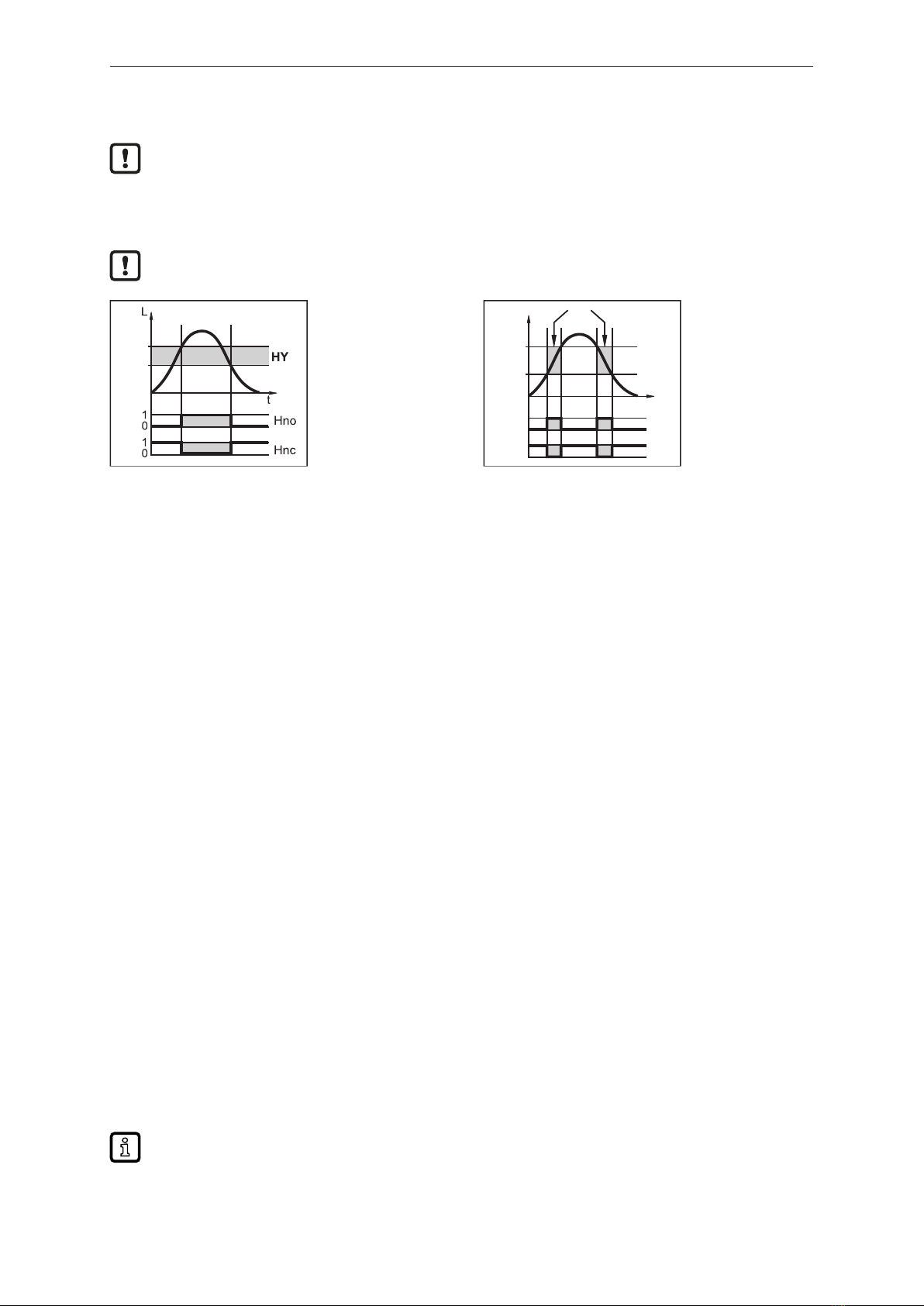
9.7.2 Setting the switching limits (hysteresis function) . . . . . . . . . . . . . . . . . . . . . . . . . . . . 27
9.7.3 Setting the switching limits (window function) . . . . . . . . . . . . . . . . . . . . . . . . . . . . . . 27
9.7.4 Setting the switch-off delay............................................ 27
9.7.5 Setting the switching logic for the outputs . . . . . . . . . . . . . . . . . . . . . . . . . . . . . . . . . 28
9.7.6 Setting response of the outputs in case of a fault . . . . . . . . . . . . . . . . . . . . . . . . . . . 28
9.7.7 Setting the delay time after signal loss . . . . . . . . . . . . . . . . . . . . . . . . . . . . . . . . . . . 28

Electronic level sensor LR7009
3
9.8 Resetting all parameters to factory setting . . . . . . . . . . . . . . . . . . . . . . . . . . . . . . . . . . . . 28
9.9 Changing basic settings .................................................. 28
9.9.1 Re-entering probe length ............................................. 28
9.9.2 Setting to another medium ............................................ 28
9.9.3 Changing the value of the type of probe used . . . . . . . . . . . . . . . . . . . . . . . . . . . . . . 29
10 Operation .................................................................. 30
10.1 Operating indicators ..................................................... 30
10.2 Reading the set parameters ............................................... 30
10.3 Changing the display unit in the Run mode . . . . . . . . . . . . . . . . . . . . . . . . . . . . . . . . . . . . 30
10.4 Error indications ........................................................ 30
10.5 Output response in different operating states . . . . . . . . . . . . . . . . . . . . . . . . . . . . . . . . . . 31
11 Repair, maintenance and disposal ............................................... 32
12 Applications ................................................................ 33
12.1 Minimum level monitoring with early warning and alarm . . . . . . . . . . . . . . . . . . . . . . . . . . 33
12.2 Pumping station / empty the tank with overflow prevention . . . . . . . . . . . . . . . . . . . . . . . . 33
12.3 Storage tank........................................................... 34
13 Factory setting .............................................................. 36

LR7009 Electronic level sensor
4
1 Preliminary note
You will find instructions, technical data, approvals and further information using the QR code on the
unit / packaging or at www.ifm.com.
1.1 Symbols used
Requirement
Instructions
Reaction, result
[...] Designation of keys, buttons or indications
Cross-reference
Important note
Non-compliance may result in malfunction or interference.
Information
Supplementary note

Electronic level sensor LR7009
5
2 Safety instructions
• The unit described is a subcomponent for integration into a system.
– The system architect is responsible for the safety of the system.
– The system architect undertakes to perform a risk assessment and to create documentation in
accordance with legal and normative requirements to be provided to the operator and user of
the system. This documentation must contain all necessary information and safety instructions
for the operator, the user and, if applicable, for any service personnel authorised by the
architect of the system.
• Read this document before setting up the product and keep it during the entire service life.
• The product must be suitable for the corresponding applications and environmental conditions
without any restrictions.
• Only use the product for its intended purpose (Ò Intended use).
• If the operating instructions or the technical data are not adhered to, personal injury and/or damage
to property may occur.
• The manufacturer assumes no liability or warranty for any consequences caused by tampering with
the product or incorrect use by the operator.
• Installation, electrical connection, set-up, operation and maintenance of the product must be
carried out by qualified personnel authorised by the machine operator.
• Protect units and cables against damage.
• Only use the product for permissible media (Ò Technical data).
• The unit complies with the standard EN 61000-6-4 and is a class A product. The unit may cause
radio interference in domestic areas. If interference occurs, the user must take appropriate actions.

LR7009 Electronic level sensor
6
3 Intended use
The device continuously monitors the level in tanks and generates output signals according to the
parameter settings.
2 switching outputs are available.
The outputs can be set separately.
In addition, the following is necessary for installation and operation:
• One rod (for operation of the device with single probe) Ò Accessories.
• Plus one coaxial pipe (for operation of the device with coaxial probe) Ò Accessories.
• Mounting material (if necessary, a launching plate) Ò Accessories.
3.1 Accessories
Only use accessories from ifm electronic gmbh. The function is not ensured when using
components from other manufacturers.
The following components are available as accessories:
Rods
Length (cm) Order number
15 E43225
24 E43203
30 E43226
45 E43204
50 E43227
70 E43205
100 E43207
120 E43208
140 E43209
160 E43210
Coaxial pipes with G¾ process connection
Length (cm) Order number
24 E43211
30 E43228
45 E43212
50 E43229
70 E43213
100 E43214
120 E43215
140 E43216
160 E43217

Electronic level sensor LR7009
7
Coaxial pipes with ¾“ NPT process connection
Length (cm) Order number
45 E43218
70 E43219
100 E43220
120 E43223
140 E43224
160 E43221
Flange plates
Size / process connection Order number
73 - 90 / G¾ E43201
65 - 80 / G¾ E43202
3.2 Operation with single probe
The single probe is made up of one individual rod and is suited for the detection of aqueous media, in
particular of heavily soiled aqueous media.
For the correct function with single probe, the device needs a large enough metal launching
plate. It is necessary for transferring the microwave pulse to the tank with optimum transmission
power.
The flange plates that are available as accessories are not sufficient as launching plates. Only
use accessories indicated as "launching plate".
For installation in closed metal tanks, the tank lid serves as a launching plate. For installation in
open metal tanks, tanks made of plastic or metal tanks with plastic lids a sufficiently large fixing
plate, a metal plate or similar must be used.
For operation with single probe, minimum distances to tank walls, objects in the tank, bottom of
the tank and further level sensors must be adhered to.
3.3 Operation with coaxial probe
The coaxial probe is made up of an inner rod and an outer probe pipe (coaxial pipe). The rod is
centred in the coaxial pipe by one or several spacers.
In case of operation with a coaxial probe media with a low dielectric constant (e.g. oil and oil-based
media) are detected in addition to aqueous media.
No launching plate is required for operation with coaxial probe. Furthermore, no minimum
distances to tank walls and objects in the tank are required.
3.4 Application area
• Water, water-based media
• Oils, oil-based media (only for operation with coaxial probe)
Application examples:
• Detection of coolant emulsion in a machine tool.
• Detection of cleaning liquid in a parts cleaning system.
• Monitoring of hydraulic oil in a hydraulic power unit (only for operation with coaxial probe).

LR7009 Electronic level sensor
8
3.4.1 Restriction of the application area
Incorrect measurements or signal loss may be caused by the following media:
Highly absorbing surfaces (e.g. foam).
Intensely bubbling surfaces.
Media which are very inhomogeneous, separate from each other thus forming separation layers
(e.g. oil layer on water).
uCheck the function by performing an application test.
uInstallation in a steady area.
wIn case of signal loss, the device displays [E.033] and switches the outputs to a defined
state.
The device is not suitable for bulk materials (e.g. plastic granulates).
The device is not suitable for applications where the probe is subjected to permanent and high
mechanical stress (e.g. heavy movement of viscous media or fast flowing media).
When installed in plastic tanks, deterioration caused by electromagnetic interference may occur (noise
immunity to EN61000-6-2).
In case of operation with coaxial probe: not suitable for soiled or viscous media and media prone to
formation of deposit. Maximum viscosity: 500mPa.s.
• If the device is to be used in acids or alkalis, in hygienic areas or in electroplating applications:
uCheck the compatibility of the product materials with the media to be monitored.
• In case of operation with single probe:
uUse preferably in metal tanks.
uIn case of operation in small tanks (rod lengths shorter than 200 mm and less than 300 mm
distance to the tank wall), interference from the tank (resonances) may occur in rare cases.

Electronic level sensor LR7009
9
4 Function
This unit has an IO-Link communication interface which enables direct access to process and
diagnostic data. In addition it is possible to set the parameters of the unit while it is in operation.
Operation of the unit via the IO-Link interface requires an IO-Link master.
With a PC, suitable IO-Link software and an IO-Link adapter cable, communication is possible while
the system is not in operation.
The IODDs necessary for the configuration of the unit, detailed information about process data
structure, diagnostic information, parameter addresses and the necessary information about the
required IO-Link hardware and software can be found at www.ifm.com.
4.1 Measuring principle
The device operates on the principle of guided wave radar. It measures the level using
electromagnetic pulses in the nanosecond range.
Fig.1: Transmitting
D
Fig.2: Receiving
The pulses are transmitted by the sensor head and guided along the rod (Fig. Transmitting). When
they hit the medium to be detected they are reflected and guided back to the sensor (Fig. Receiving).
The time between transmitting and receiving the pulse directly relates to the travelled distance (D) and
the current level. The reference for distance measurement is the lower edge of the process
connection.
The figures show operation with single probe. In case of operation with a coaxial probe, the
guided wave runs only along the inside of the coaxial pipe.
4.2 Display functions
The device displays the current level, either in cm or in percent of the final value of the measuring
range. Factory setting: cm.
The display unit is defined by programming. In the Run mode, it can be temporarily switched between
length indication (cm) and percentage:
uBriefly press [Set].
wThe selected unit is displayed for 30 s, the corresponding LED is lit. With each push of the button
the display type is changed.
The set unit of measurement and the switching status of the outputs are indicated by LEDs.
4.3 Switching function
The device signals via two switching outputs (OUT1/OUT2) that a set limit value has been reached or
that the level is below the limit value. For each output the following switching functions can be
selected:
• Hysteresis function / normally open (Fig. Hysteresis function): [OUx] = [Hno].

LR7009 Electronic level sensor
10
• Hysteresis function / normally closed (Fig. Window function): [OUx] = [Hnc].
First the switch point (SPx) is set, then the switch-off point (rPx) with the requested difference.
• Window function / normally open (Fig. Hysteresis function): [OUx] = [Fno].
• Window function / normally closed (Fig. Window function): [OUx] = [Fnc].
The width of the window can be set by means of the difference between FHx and FLx.
FHx = upper value, FLx = lower value.
SP
rP
Fig.3: Hysteresis function
L: level
HY: hysteresis
FE: window
t
L
FH
FL
1
0
1
0
FE
Fno
Fnc
Fig.4: Window function
L: level
HY: hysteresis
FE: window
For each switching output, a switch-off delay of max. 60 s can be set (e.g. for especially long pump
cycles).
4.4 Offset for indicating the real level in the tank
The zone between tank bottom and lower edge of the probe can be entered as offset value [OFS]. So
display and switch points refer to the actual level.
4.5 Probes for different tank heights
The device can be installed in tanks of different sizes. Probes in different lengths are available. To
adapt to the tank height, each probe can be shortened. The minimum probe length is 10 cm, the
maximum probe length is 160 cm.
Probe and housing can be rotated without restriction. This enables easy installation and orientation of
the head of the device after installation.
4.6 Safe state
For each output, a safe state in the event of a fault can be defined.
If a fault is detected or if the signal quality is below a minimum value, the outputs pass into the "safe
state". For this case the response of the outputs can be set via the parameters [FOU1], [FOU2].
Temporary loss of signal caused e.g. by turbulence or foam formation can be suppressed by a delay
time [dFo].
During the delay time the last measured value is frozen. If the measured signal is received again in
sufficient strength within the delay time, the device continues to work in normal operation. If, however,
it is not received again in sufficient strength within the delay time, the outputs pass into the safe state.
In case of heavy foam build-up and turbulence:
uNote the examples of how to create a steady area.

Electronic level sensor LR7009
11
5 Installation
Vertical installation from the top is preferred.
5.1 Device with single probe
For a safe function, the device requires a launching plate.
The following minimum distances between the rod and tank walls, objects in the tank (B), tank bottom
and other level sensors must be adhered to:
50mm
10mm
100mm
B40mm
For tank walls which are not straight, steps, supports or other structures in the tank a distance of 50
mm to the tank wall must be adhered to.
When operating the device in small tanks (rod lengths shorter than 200 mm and less than 300 mm
distance to the tank wall), mount the device off-centre (eccentrically) to prevent possible interference
from tank resonances.
For probe lengths > 70 cm the rod can be considerably deflected by movement of the medium. To
avoid contacting the tank wall or other structures in the tank in such cases, the minimum distances
should be increased. Reference values:
Probe length Distance to the tank wall or structures in the tank
70...100cm 100mm
100...160cm 180mm
If the medium is highly polluted, there is the risk that a bridge forms between the rod and the tank wall
or structures in the tank. To avoid incorrect measurements: adhere to increased minimum distances
depending on type and intensity of the soiling.
For installation in pipes:
• The inside pipe diameter (d) must be at least 100 mm (Fig. Installation on a pipe).
• If possible, mount the device off-centre (eccentrically).
• Only install the device in metal pipes.
For installation in a boss:
• The diameter of the boss (d) must be at least 60 mm (Fig. Installation in a boss).
• The height of the boss (h) must not exceed 40 mm (Fig. Installation in a boss).

LR7009 Electronic level sensor
12
d
Fig.5: Installation on a pipe
d
h
Fig.6: Installation in a boss
Although the device can be installed in a boss: installation in a flat tank lid is recommended, as
a boss will impede the distribution of the microwaves.
Do not install the device in the immediate vicinity of a fill opening. If possible, install a fill pipe (A) in the
tank. Minimum distance between the fill pipe and the rod = 50 mm; higher for probe lengths > 70 cm
and in case of heavy soiling.
50mm
A
To avoid incorrect measurements in case of heavy foam formation and turbulence:
uIf possible, install the sensor in a steady area.
Examples of how to create a steady area:
uUse of a coaxial probe (only for clean, low-viscosity media)
uInstallation in bypass or still pipe
uSeparation of the installation location by metal sheets / perforated sheets (without figure)
Min. diameter of the bypass and still pipe: d = 100 mm.
The upper access to the steady area (Fig. A / B) must be above the max. level. The lower
access (Fig. C / D) or the area with perforated sheet etc. must be below the min. level. This
ensures that neither foam nor turbulence impact the sensor zone. Besides, the use of
perforated sheets or the like can help to avoid soiling (e.g. by metal swarf, particles).

Electronic level sensor LR7009
13
d
d
AB
CD
d: Min. diameter bypass and still pipe
A: Upper access to the steady area
B: Upper access to the steady area
C: Lower access to the steady area
D: Lower access to the steady area
5.2 Device with coaxial probe
A
B
10 mm
• No minimum distances to the tank wall and structures in the tank (B)
are required.
uMinimum distance to the bottom of the tank: 10mm.
uThe vent hole (A) must not be covered by mounting elements or
similar.
uDo not install the device in the immediate vicinity of a fill opening. No
water jets must enter into the holes of the coaxial pipe.
Note in case of foam build-up:
uThe vent of the coaxial pipe must be above the maximum level.
uThe lower edge of the coaxial pipe must be below the minimum level.
5.3 Installation of the probe
Rod and coaxial pipe are not included in the scope of delivery. They must be ordered separately: Ò
Accessories.
5.3.1 Installation of the rod
Fixing of the rod:
6
uScrew the rod to the device and tighten it.
Tightening torque:4 Nm
For ease of installation and removal the rod connection can be rotated
without restriction. Even if rotated several times there is no risk of
damage to the device.
In case of high mechanical stress (strong vibration, moving viscous media) it may be necessary to
secure the screw connection, e.g. by a screw retaining compound.

LR7009 Electronic level sensor
14
Substances such as screw retaining compounds may migrate into the medium.
uMake sure that they are harmless.
When using mechanical means of securing (e.g. tooth lock washer), protruding edges must be
avoided. They may cause interference reflection.
5.3.2 Installation of the coaxial pipe
This chapter is only relevant if the device is to be operated with a coaxial probe.
The coaxial pipe and the rod must be of the same end length. The coaxial pipe can be
shortened.
A
C
B
32
32
uScrew the rod to the device and tighten it.
Tightening torque:4 Nm.
uSlide the sensor seal (A) onto the thread.
uSlide the coaxial pipe (B) onto the rod. Carefully centre it and
carefully move the rod through the centring piece (C) – for lengths
>140 cm through both centring pieces – of the coaxial pipe. Do not
damage the centring pieces.
uScrew onto the sensor thread and tighten.
5.4 Shortening of the probe
5.4.1 Shortening of the rod and determination of its length L
The rod can be shortened to adapt to different tank heights.
Ensure that the probe length is never below the minimum permissible length (Lmin) of 10 cm! The
device does not support probe lengths below 10 cm. If shorter probes are used, measurement
errors can occur.
Lmin
L
uScrew the rod to the device.
uMark the desired length (L) on the rod. The reference point is the
lower edge of the process connection.
uRemove the rod from the device.
uShorten the rod at the mark.
uRemove all burrs and sharp edges.
uScrew the rod to the device again and tighten it.
Tightening torque:4 Nm.
uPrecisely measure the probe length L and note the value. It must be
entered during parameter setting of the device.
5.4.2 Shortening of the coaxial pipe
The coaxial pipe and the rod must be of the same end length:

Electronic level sensor LR7009
15
AB
C
uRemove the fastening bracket and the centring piece (A, B).
uShorten the coaxial pipe to the requested length: LK = L+9mm.
uAfter shortening, at least one hole (C) for insertion of the fixing
bracket has to be left.
uRemove all burrs and sharp edges.
uInsert the centring piece (A) at the lower end of the pipe and attach it
using the fixing bracket (B) at the lower hole (C).
LK: length of the coaxial pipe
L: length of the rod from the lower edge of the process connection
5.4.3 Determination of the probe length L when coaxial probes are used
Only relevant if the rod length L is unknown:
uMeasure the exact total length LK of the coaxial pipe.
uDeduct 9mm from the total length of the coaxial pipe: LK – 9 mm = L
uNote down L. It must be entered during parameter setting of the device.
5.5 Installation of the device with single probe
For the correct function when used with single probe, the device needs a large enough metal
launching plate. It is necessary for transferring the microwave pulse to the tank with optimum
transmission power.
For installation in closed metal tanks, the tank lid serves as a launching plate. Two ways of installation
are possible:
• Screw in a G¾ process connection in the tank lid.
• Installation in the tank lid using a flange plate, e.g. for tanks with thin walls.
Furthermore, installation in open tanks and plastic tanks is possible.
5.5.1 Installation in closed metal tanks (without flange plate)
R
32
R: tank lid /
launching plate
uEnsure that the lower edge of the process connection is flush with
the installation environment.

LR7009 Electronic level sensor
16
uAvoid non-flush installation.
D
uIf necessary, use seals or washers (D) to reach the required height.
uFor tanks with thick walls arrange for sufficiently deep recesses to
ensure flush installation.
5.5.2 Installation in closed metal tanks (with flange plate)
Flange plates are not supplied. They must be ordered separately: Ò Accessories.
d
uArrange for a hole in the tank lid. It must have a minimum diameter
(d) to enable sufficient transfer of the measured signal to the probe.
The diameter depends on the wall thickness of the tank lid:
Wall thickness [mm] 1...5 5...8 8...11
Bore hole diameter d [mm] 35 45 55
uInstall the flange plate with the flat surface showing to the tank and fix it with appropriate screws.
A B
R
A. sensor seal
B: tank seal
R: tank lid / launching plate
A seal (B) can be inserted between flange plate and tank. Some flange plates are supplied with
a seal.
uEnsure cleanness and evenness of the sealing areas, especially if the tank is under pressure.
Tighten the fixing screws sufficiently.
uScrew the device into the flange plate using the process connection and tighten firmly.
uMake sure that the supplied sensor seal (A) is correctly positioned.

Electronic level sensor LR7009
17
5.5.3 Installation in open tanks
uFor installation in open tanks, use a metal fixture to install the device. It serves as a launching plate
(R); minimum size: 150 x 150 mm for a square fixture, 150 mm diameter for a circular fixture: (Ò
Accessories).
uMount the device in the middle of the fixture. The distance D2 must not be below 40 mm, higher for
probe lengths > 70 cm and in case of heavy soiling.
D2
150 mm
R
R: fixture / launching plate
D2: distance to the fixture
uEnsure that the lower edge of the process connection is flush with the installation environment.
uAvoid non-flush installation.
uIf necessary, use seals or washers to reach the required height.
5.5.4 Installation in plastic tanks
150 mm
R
R: flange plate
To enable sufficient transfer of the measured signal, note in case of installation in plastic tanks
or metal tanks with plastic lid:
uThere must be a hole of at least 150 mm in diameter in the plastic lid.
uFor installation of the device, a metal flange plate (= launching plate R) must be used which
sufficiently covers the drill hole: (Ò Accessories).
uEnsure the minimum distance (= 80 mm) between rod and tank wall, higher for probe lengths
> 70 cm and in case of heavy soiling.
When installed in plastic tanks, there may be deterioration caused by electromagnetic
interference. Corrective measures:
uApply a metal foil to the outside of the tank.
uApply a shielding screen between the level sensor and other electronic devices.
uOperation with coaxial probe efficiently protects the device from electromagnetic
interference. Please note the restrictions regarding the application area.
5.6 Installation of the device with coaxial probe in the tank
uSeal the process connection:
• For pipes with G¾ process connection:
slide the supplied seal onto the thread of the coaxial pipe.

LR7009 Electronic level sensor
18
• For pipes with ¾" NPT process connection:
apply a suitable sealing material (e.g. Teflon tape).
uScrew the device with the coaxial pipe into the tank and tighten it.
5.7 Alignment of the sensor housing
After installation, the sensor housing can be aligned. It can be rotated without restriction. Even if
rotated several times there is no risk of damage to the device.

Electronic level sensor LR7009
19
6 Electrical connection
The device must be connected by a qualified electrician.
The national and international regulations for the installation of electrical equipment must be
adhered to.
Supply voltage SELV, PELV according to the technical data sheet.
uDisconnect power.
uConnect the device as follows:
When the device is supplied with operating voltage for the first time, the probe length, the
medium to be detected and the type of probe used must be entered. Only then is the device
ready for operation.
L
1 BN
2 WH
4 BK
3 BU
OUT1/IO-Link
OUT2
L+
43
2 1
Pin Core colour
1: BN brown
2: WH white
3: BU blue
4: BK black
OUT1:
• Switching output
• IO-Link
OUT2:
• Switching output
Colours to DIN EN 60947-5-2

LR7009 Electronic level sensor
20
7 Operating elements and display elements
2345678
9
10
1
Mode/Enter Set
cm
%
OUT1
11
OUT2
1 to 8: Indicator LEDs
LED 1 green = indication of the level in cm.
LED 2 not used.
LED 3 green = indication of the level in % of the final value of the measuring range.
LED 4 – LED 6 not used.
LED 7 yellow = output 2 is switched.
LED 8 yellow = output 1 is switched.
9: Alphanumeric display, 4 digits
• Indication of the current level.
• Operation and fault indication.
• Indication of the parameters and parameter values.
10: Set button
• Setting of the parameter values (scrolling by holding pressed, incrementally by pressing once).
• Change between cm indication and percent indication in the normal operating mode (Run mode).
11: Mode/Enter button
• Selection of the parameters and acknowledgement of the parameter values.
Table of contents
Other IFM Accessories manuals

IFM
IFM O5H5xA Series User manual

IFM
IFM Efector 200 OM User manual

IFM
IFM SI 5000 User manual

IFM
IFM 402946 User manual

IFM
IFM PI17 Series User manual

IFM
IFM VSP003 User manual

IFM
IFM Efector 200 Series User manual

IFM
IFM PI109 Series User manual

IFM
IFM Efector600 TN2531 User manual

IFM
IFM O2D54 Series User manual
Popular Accessories manuals by other brands

Kenton
Kenton MC-202 Instructions for using

Seiko
Seiko Oxford Crossword Solver ER3000 Operation manual

Adeunis RF
Adeunis RF MOTION V2 Technical reference manual

DIGITAL YACHT
DIGITAL YACHT GPS160F Installation and instruction manual

Baumer
Baumer Hubner GT 9 Mounting and operating instructions

Polaroid
Polaroid PLAY PL-2000-00 quick start guide