IFM DTE603 User manual

Installation instructions
RFID compact unit
DTE601
DTE602
DTE603
DTE604
80282046 / 00 02 / 2019
UK

2
Contents
1 Preliminary note���������������������������������������������������������������������������������������������������4
1�1 Symbols used ������������������������������������������������������������������������������������������������4
1�2 Warnings used�����������������������������������������������������������������������������������������������4
1�3 Copyright and trademarks �����������������������������������������������������������������������������4
2 Safety instructions �����������������������������������������������������������������������������������������������4
3 Functions and features ����������������������������������������������������������������������������������������5
3�1 Configuration via Ethernet interface ��������������������������������������������������������������6
4 Items supplied������������������������������������������������������������������������������������������������������6
5 Function���������������������������������������������������������������������������������������������������������������6
5�1 Operating principle ����������������������������������������������������������������������������������������6
5�2 Overview DTE601������������������������������������������������������������������������������������������7
5�3 Overview DTE602������������������������������������������������������������������������������������������7
5�4 Overview DTE603������������������������������������������������������������������������������������������7
5�5 Overview DTE604������������������������������������������������������������������������������������������8
6 Installation������������������������������������������������������������������������������������������������������������8
6�1 General installation instructions���������������������������������������������������������������������8
6�2 Notes on ID tag mounting������������������������������������������������������������������������������8
6�3 Avoiding interference �������������������������������������������������������������������������������������8
6�4 Mechanical design�����������������������������������������������������������������������������������������9
6�5 Installation options�����������������������������������������������������������������������������������������9
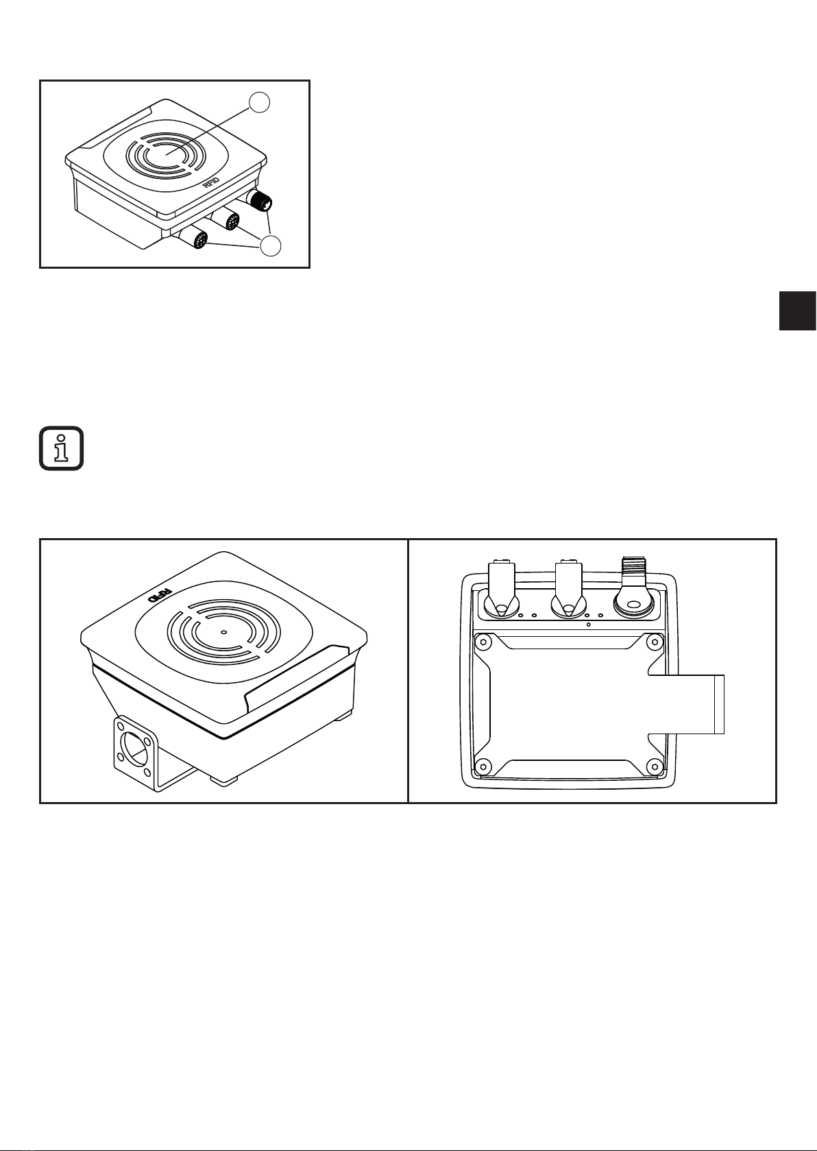
6�5�1 Installation with angle bracket E80335 �������������������������������������������������9
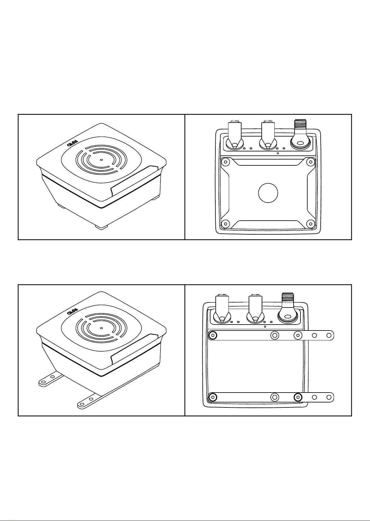
6�5�2 Installation with mounting device E80336 ������������������������������������������10
6�5�3 Installation with fixing bars E80337 ����������������������������������������������������10
6�6 Mounting distances�������������������������������������������������������������������������������������� 11
6�7 Positioning of the ID tags����������������������������������������������������������������������������� 11
7 Electrical connection������������������������������������������������������������������������������������������12
7�1 Voltage supply PWR������������������������������������������������������������������������������������12
7�2 Ethernet �������������������������������������������������������������������������������������������������������13
7�2�1 Factory setting of the Ethernet parameters ����������������������������������������13
7�3 Functional earth connection ������������������������������������������������������������������������14
7�3�1 Mounting plate ������������������������������������������������������������������������������������14
8 Operating and display elements ������������������������������������������������������������������������15
8�1 Reset to factory settings ������������������������������������������������������������������������������15

3
UK
8�2 LED indicators ���������������������������������������������������������������������������������������������16
8�2�1 Power LEDs and signal bar ����������������������������������������������������������������16
8�2�2 LED LINK/ACT ETH 1 / ETH 2 �����������������������������������������������������������16
8�2�3 Special device LED indicators ������������������������������������������������������������17
8�3 LED indicators DTE601 �������������������������������������������������������������������������������18
8�3�1 LED SF �����������������������������������������������������������������������������������������������18
8�3�2 LED BF �����������������������������������������������������������������������������������������������18
8�4 LED indicators DTE602 �������������������������������������������������������������������������������19
8�4�1 LED Mod (module status)�������������������������������������������������������������������19
8�4�2 LED Net (network status) �������������������������������������������������������������������20
8�5 LED indicators DTE603 �������������������������������������������������������������������������������21
8�5�1 RUN LED �������������������������������������������������������������������������������������������21
8�5�2 LED ERR ��������������������������������������������������������������������������������������������21
8�6 LED indicators DTE604 �������������������������������������������������������������������������������22
8�6�1 LED SF �����������������������������������������������������������������������������������������������22
8�6�2 LED BF �����������������������������������������������������������������������������������������������22
9 Technical data����������������������������������������������������������������������������������������������������23
9�1 Data sheet ���������������������������������������������������������������������������������������������������23
9�2 Device manual���������������������������������������������������������������������������������������������23
10 Maintenance, repair and disposal��������������������������������������������������������������������23
11 Approvals/standards ����������������������������������������������������������������������������������������23
11�1 Radio approvals�����������������������������������������������������������������������������������������23
11�1�1 Overview�������������������������������������������������������������������������������������������23
11�1�2 Europe ����������������������������������������������������������������������������������������������23
11�2 EU declaration of conformity����������������������������������������������������������������������23
12 Scale drawing ��������������������������������������������������������������������������������������������������24

4
1 Preliminary note
Technical data, approvals, accessories and further information →
www�ifm�com�
1.1 Symbols used
►Instruction
> Reaction, result
[…] Designation of keys, buttons or indications
→Cross-reference
Important note
Non-compliance may result in malfunction or interference�
Information
Supplementary note
1.2 Warnings used
ATTENTION!
Kind and source of the hazard
> Possible consequences�
►Actions to refrain from�
►Measures to take�
1.3 Copyright and trademarks
© All rights reserved by ifm electronic gmbh� No part of these instructions may be
reproduced and used without the consent of ifm electronic gmbh�
All product names, pictures, companies or other brands used on our pages are the
property of the respective rights owners�
2 Safety instructions
• The device described is a subcomponent for integration into a system�
- The manufacturer is responsible for the safety of the system�
- The system manufacturer undertakes to perform a risk assessment and to
create a documentation in accordance with legal and normative requirements
to be provided to the operator and user of the system� This documentation
must contain all necessary information and safety instructions for the operator,

5
UK
the user and, if applicable, for any service personnel authorised by the
manufacturer of the system�
• Read this document before setting up the product and keep it during the entire
service life�
• The product must be suitable for the corresponding applications and
environmental conditions without any restrictions�
• Only use the product for its intended purpose (→ Functions and features).
• If the operating instructions or the technical data are not adhered to, personal
injury and/or damage to property may occur�
• The manufacturer assumes no liability or warranty for any consequences
caused by tampering with the product or incorrect use by the operator�
• Installation, electrical connection, set-up, operation and maintenance of the
product must be carried out by qualified personnel authorised by the machine
operator�
• Protect the device and the cables against damage�
• Use the device outside petrol stations, fuel depots, chemical plants or blasting
operations�
• Do not transport and store any flammable gases, liquids or explosive
substances near the device�
• Operation of the device can affect the function of electronic devices that are not
correctly shielded�
- Disconnect the device in the vicinity of medical equipment�
- Contact the manufacturer of the corresponding device in case of any
interference�
• Because of the requirements for electromagnetic interference emissions, the
device is intended for use in industrial environments� The device is not suitable
for use in domestic areas�
• Device safety: Use the device indoors only�
3 Functions and features
The DTE60x device is composed of an evaluation unit and an integrated RFID
compact unit with the following functions:
• read and write ID tags which conform to the system without contact,

6
• DTE601: communication with the control level via PROFINET IO,
• DTE602: communication with the control level via EtherNet/IP,
• DTE603: communication with the control level via EtherCAT,
• DTE604: communication with the control level via EtherNet TCP/IP,
• can be configured via a web server�
Example applications:
• material flow control in production lines
• warehouse management by the automatic detection of stored products
• tank management, order picking or product tracking
The device may only be used under the operating conditions specified in
the data sheet�
3.1 Configuration via Ethernet interface
• 10 Mbps and 100 Mbps
• TCP/IP - Transport Control Protocol / Internet Protocol
• IT functionality: HTTP server
• M12, twisted pair
4 Items supplied
• DTE60x RFID compact unit
• Installation instructions
The device is supplied without installation and connection accessories�
In the event of incomplete or damaged items supplied, please contact ifm
electronic�
5 Function
5.1 Operating principle
The ID tags are operated passively, i�e� without battery� The energy required for
operation is supplied by the RFID compact unit�
The physical principle of the energy transfer is based on inductive coupling� The
integrated antenna coil in the RFID compact unit generates a magnetic field

7
UK
which partly penetrates the antenna coil of the ID tag� A voltage is generated by
induction that supplies the data carrier with energy�
5.2 Overview DTE601
Art� no�:
Function:
Type designation:
Operating frequency:
Type:
Max� transmitter power:
DTE601
RFID compact unit
DTRHF HLRWPNUS03
13�56 Mhz
rectangular
2 watts
Fig� 1: Overview DTE601
5.3 Overview DTE602
Art� no�:
Function:
Type designation:
Operating frequency:
Type:
Max� transmitter power:
DTE602
RFID compact unit
DTRHF HLRWEIUS03
13�56 Mhz
rectangular
2 watts
Fig� 2: Overview DTE602
5.4 Overview DTE603
Art� no�:
Function:
Type designation:
Operating frequency:
Type:
Max� transmitter power:
DTE603
RFID compact unit
DTRHF HLRWECUS03
13�56 Mhz
rectangular
2 watts
Fig� 3: Overview DTE603

8
5.5 Overview DTE604
Art� no�:
Function:
Type designation:
Operating frequency:
Type:
Max� transmitter power:
DTE604
RFID compact unit
DTRHF HLRWENUS03
13�56 Mhz
rectangular
2 watts
Fig� 4: Overview DTE604
6 Installation
6.1 General installation instructions
When mounting several RFID compact units adhere to the minimum
distances between the systems�
Installing a RFID compact unit in or on metal reduces the read and write
distance�
The immediate vicinity of powerful HF emission sources such as welding
transformers or converters can affect operation of the RFID compact units�
Available accessories: www�ifm�com
6.2 Notes on ID tag mounting
Installation of the ID tags in and on metal reduces the read and write
distances�
For positioning the ID tags the RFID compact units are marked with
an antenna symbol on the active face� It designates the middle of the
integrated antenna coil and has to correspond with the middle of the ID tag�
The orientation of the RFID compact unit axis must correspond with the
axis of the ID tag coil�
6.3 Avoiding interference
The device generates a modulated electrical field with a frequency of 13�56 MHz�
To avoid interference of the data communication no other devices generating
interference emission in this frequency band must be operated in its vicinity� Such
devices are for example frequency converters and switched-mode power supplies�

9
UK
6.4 Mechanical design
1
2
1: sensing face
2: connection (can be rotated by 270°)
Fig� 5: Mechanical design
6.5 Installation options
For installation, the following optional accessories are available�
The device can be mounted without the accessories� For installation,
please use the threaded sleeves on the back of the device� The necessary
screws are not supplied with the device�
6.5.1 Installation with angle bracket E80335
Fig� 6: Installation with angle bracket E80335

10
6.5.2 Installation with mounting device E80336
The mounting device is used to fix the device to a clamp� The following clamps
can be used:
• E21110 with a rod diameter of 12 mm
• E20795 with a rod diameter of 14 mm
• E21109 with a rod diameter of 14 mm
Fig� 7: Installation with mounting device E80336
6.5.3 Installation with fixing bars E80337
Fig� 8: Installation with fixing bars E80337
►Fix the device with fixing screws to the designated location�

11
UK
6.6 Mounting distances
Fig� 9: Mounting distances
Operating mode Distance side (A) Distance front (B)
Read and write
(at 100% transmitter power)
≥ 850 mm ≥ 600 mm
6.7 Positioning of the ID tags
D
►Align the ID tag on the
antenna central axis�
> Distance D see data
sheet
Fig� 10: Position of the ID tag

12
7 Electrical connection
NOTE
The device must be connected by a qualified electrician�
Device of protection class III (PC III)
Electric supply via SELV circuits only�
►Disconnect power before connecting the device�
►For cable lengths > 30 m use an additional protection against surge voltages to
IEC 61000-4-5�
►A total current consumption of the device of 0�5 A must not be exceeded�
NOTE
The IP rating indicated in the data sheet is only guaranteed if the M12 connectors are
firmly screwed�
The unit can be damaged by insufficiently tightened M12 connectors�
►Firmly screw the M12 connectors to the device�
7.1 Voltage supply PWR
►Connect the device to the voltage supply using an M12 connection cable�
3
12
4
5
Pin Connection
1 24 V DC
2 digital input / output 2
3 0 V
4 digital input / output 1
5 not connected
Fig� 11: Pin connection voltage supply
Matching connection cables are available: www�ifm�com

13
UK
7.2 Ethernet
►Connect the device to a PC using a suitable M12 Ethernet connection cable�
The M12 Ethernet cable must be screened to ensure interference-free
operation�
12
34
Pin Connection
1 TD+
2 RD+
3 TD-
4 RD-
Fig� 12: Pin connection fieldbus connection
7.2.1 Factory setting of the Ethernet parameters
The following values are preset at the factory:
Parameter Factory setting
IP address 192�168�0�79
Gateway address 192�168�0�100
Subnet mask 255�255�255�0
Auto-negotiation on
DHCP off
The settings can be changed via the web server of the device or via the PC�

14
7.3 Functional earth connection
To ensure interference-free operation, the device must be connected to an
earth potential free from external voltage�
7.3.1 Mounting plate
When the device is fixed on a mounting plate, the connection is made via one of
the four mounting bolts on the back� Note that the plate must be connected with
the earth potential�
Fig� 13: Mounting plate

15
UK
8 Operating and display elements
1
2
①
:
②
:
1 power LED (green)
4 LEDs on signal bar (yellow)
2 fieldbus LEDs (green/red)
sensing face
Fig� 14: Operating and display elements
8.1 Reset to factory settings
The Ethernet parameters can be reset to factory setting� To do so, proceed as
follows:
►Remove all cable connections from the device�
►Insert an electrically conductive bridge between pin 2 and pin 4 on the process
connection voltage supply PWR�
►Connect the device to the voltage supply�
> The LEDs of the signal bar (yellow) are on one after the other� Then LED 4 of
the signal bar (yellow) flashes at 8 Hz�
►As soon as the LEDs of the signal bar (yellow) flash at 8 Hz, disconnect the
device�
►Remove the bridge�
►Connect the device to the voltage supply�
> The parameters are reset�

16
8.2 LED indicators
The following LED indicators apply to all DTE60x devices�
8.2.1 Power LEDs and signal bar
LED PWR
(1x green)
LED signal bar
(4x yellow)
Status Note
on off voltage supply OK 18 V ≤ UAUX ≤ 36 V
flashing at
2 Hz off antenna (HF field) is
deactivated
on flashes twice ID tag read/written
successfully
on flashing quickly ID tag read/written incorrectly
If the ID tag has a high receive signal strength, all LEDs of the signal bar
are on (configurable)�
The maximum receive signal strength depends on the type of the ID tag�
8.2.2 LED LINK/ACT ETH 1 / ETH 2
LED green LED yellow Status Note
off off no connection to another
Ethernet counterpart link status "no link"“
on off
connection to Ethernet
counterpart exists, no data
exchange
link status "link", "no traffic"
on flashes
sporadically
connection to Ethernet
counterpart exists, data
exchange running
link status "link", "traffic"

17
UK
8.2.3 Special device LED indicators
LED Status Note
PWR LED (green) on
LEDs of signal bar
(yellow) flashing at 8 Hz
device is in the service mode
"emergency system started"
A firmware update is
necessary and can be
executed via the web server�
PWR LED (green) on
LEDs of signal bar
(yellow) flashing at 8 Hz
major error, device has to be
returned
hardware fault or permanent
data in the device are corrupt
PWR LED (green) on
The LEDs of the signal
bar (yellow) are on one
after the other� Then
LED 4 of the signal bar
(yellow) flashes at 8 Hz�
reset to factory settings -

18
8.3 LED indicators DTE601
The following LED indicators only apply to DTE601�
8.3.1 LED SF
LED red LED green Status Note
off off no voltage supply check the voltage supply
off flashing "node flash test", initiated by
PROFINET IO controller -
off on normal operation -
flashing off error at channel level
- overload
- temperature
- internal fault
on off error at device level - undervoltage
- temperature
flashing flashing self-test starting phase of the device
8.3.2 LED BF
LED red LED green Status Note
off off no voltage supply check the voltage supply
off flashing PROFINET IO controller is in
STOP mode -
off on PROFINET IO controller is in
RUN mode -
flashing off
connection to the PROFINET
IO controller is established,
no valid configuration
check configuration
on off no connection to the
PROFINET IO controller check connection
flashing flashing self-test starting phase of the device

19
UK
8.4 LED indicators DTE602
The following LED indicators only apply to DTE602�
8.4.1 LED Mod (module status)
LED red LED green Status Note
off off no voltage supply check the voltage supply
off flashing ready for operation
Device is not configured�
There is no exchange of data:
►Check the connection of
the Ethernet/IP scanner�
►Check the parameter
setting of the configuration
assembly�
off on normal operation
Connection to the EtherNet/
IP scanner is established�
The device is configured� The
data transfer is running�
flashing off minor error
A connection to the EtherNet/
IP scanner was not
established:
►Check the voltage supply�
►Check the configuration of
the device�
on off major error
Software / hardware error of
the device:
►Reboot the device�
> If the error remains, send
the device to the service�
flashing flashing self-test starting phase of the device

20
8.4.2 LED Net (network status)
LED red LED green Status Note
off off no IP address or no voltage
supply
►check the voltage supply
►If DHCP is activated,
check presence of a
DHCP server in the
network�
off flashing no connection
The device has received an
IP address� An EtherNet/
IP connection was not
established�
►Check the configuration of
the device via EtherNet/IP
scanner�
off on connection exists
At least one EtherNet/IP
connection to the device was
established�
flashing off timeout of the connection
A timeout was found with one
of the existing EtherNet/IP
connections�
►Check the status of
the connection in the
EtherNet/IP scanner�
on off IP address exists already
The same IP address as that
of the device was detected in
the EtherNet/IP network�
►Activate DHCP�
flashing flashing self-test starting phase of the device
This manual suits for next models
3
Table of contents
Other IFM RFID System manuals