IFM DTE801 User manual

Operating instructions
RFID compact unit
DTE801/DTE802/DTE804/DTE805
DTE901/DTE902/DTE904/DTE905
80291447 / 00 07 / 2020
UK

2
Contents
1 Preliminary note���������������������������������������������������������������������������������������������������4
1�1 Symbols used ������������������������������������������������������������������������������������������������4
1�2 Warnings used�����������������������������������������������������������������������������������������������4
1�3 Copyright and trademarks �����������������������������������������������������������������������������4
2 Safety instructions �����������������������������������������������������������������������������������������������4
3 Functions and features ����������������������������������������������������������������������������������������5
3�1 Configuration via Ethernet interface ��������������������������������������������������������������6
4 Items supplied������������������������������������������������������������������������������������������������������6
5 Function���������������������������������������������������������������������������������������������������������������6
5�1 Operating principle ���������������������������������������������������������������������������������������6
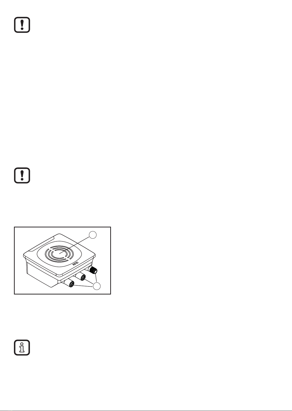
5�2 Overview DTE801������������������������������������������������������������������������������������������7
5�3 Overview DTE901������������������������������������������������������������������������������������������7
5�4 Overview DTE802������������������������������������������������������������������������������������������7
5�5 Overview DTE902������������������������������������������������������������������������������������������8
5�6 Overview DTE804������������������������������������������������������������������������������������������8
5�7 Overview DTE904������������������������������������������������������������������������������������������8
5�8 Overview DTE805������������������������������������������������������������������������������������������8
5�9 Overview DTE905������������������������������������������������������������������������������������������9
6 Installation������������������������������������������������������������������������������������������������������������9
6�1 General installation instructions���������������������������������������������������������������������9
6�2 Notes on ID tag mounting������������������������������������������������������������������������������9
6�3 Avoiding interference �����������������������������������������������������������������������������������10
6�4 Mechanical design���������������������������������������������������������������������������������������10
6�5 Mounting options �����������������������������������������������������������������������������������������10
6�5�1 Installation with angle bracket E80335 ����������������������������������������������� 11
6�5�2 Installation with mounting device E80336 ������������������������������������������ 11
6�5�3 Installation with fixing bars E80337 ����������������������������������������������������12
6�6 Mounting distances��������������������������������������������������������������������������������������12
6�7 Positioning of the ID tags�����������������������������������������������������������������������������13
7 Electrical connection������������������������������������������������������������������������������������������13
7�1 Voltage supply PWR������������������������������������������������������������������������������������14
7�2 Ethernet �������������������������������������������������������������������������������������������������������14
7�2�1 Factory setting of the Ethernet parameters ����������������������������������������15

3
UK
7�3 Functional earth connection ������������������������������������������������������������������������15
7�3�1 Mounting plate ������������������������������������������������������������������������������������15
8 Operating and display elements ������������������������������������������������������������������������16
8�1 Reset to factory settings ������������������������������������������������������������������������������16
8�2 LED indicators ���������������������������������������������������������������������������������������������16
8�2�1 Power LEDs and signal bar ����������������������������������������������������������������17
8�2�2 LED signal bar ������������������������������������������������������������������������������������17
8�2�3 LED LINK/ACT ETH 1 / ETH 2 �����������������������������������������������������������18
8�2�4 Special device LED indicators ������������������������������������������������������������18
8�3 LED indicators DTE801/DTE901�����������������������������������������������������������������19
8�3�1 LED SF �����������������������������������������������������������������������������������������������19
8�3�2 LED BF �����������������������������������������������������������������������������������������������19
8�4 LED indicators DTE802/DTE902�����������������������������������������������������������������20
8�4�1 LED Mod (module status)�������������������������������������������������������������������20
8�4�2 LED Net (network status) �������������������������������������������������������������������21
8�5 LED indicators DTE804/DTE805/DTE904/DTE905 ������������������������������������22
8�5�1 LED SF �����������������������������������������������������������������������������������������������22
8�5�2 LED BF �����������������������������������������������������������������������������������������������22
9 Maintenance, repair and disposal����������������������������������������������������������������������23
10 Approvals/standards ����������������������������������������������������������������������������������������23
10�1 Radio approvals�����������������������������������������������������������������������������������������23
10�1�1 Overview�������������������������������������������������������������������������������������������23
10�1�2 Europe / EU declaration of conformity����������������������������������������������23
10�1�3 USA ��������������������������������������������������������������������������������������������������23
10�1�4 Canada ���������������������������������������������������������������������������������������������24
10�1�5 Taiwan ����������������������������������������������������������������������������������������������24
10�1�6 Australia��������������������������������������������������������������������������������������������25
10�1�7 Singapore �����������������������������������������������������������������������������������������25
11 Scale drawing ��������������������������������������������������������������������������������������������������25

4
1 Preliminary note
Technical data, approvals, accessories and further information →
www�ifm�com�
1.1 Symbols used
►Instruction
> Reaction, result
[…] Designation of keys, buttons or indications
→Cross-reference
Important note
Non-compliance may result in malfunction or interference�
Information
Supplementary note
1.2 Warnings used
NOTE!
Kind and source of the hazard
> Possible consequences�
►Actions to refrain from�
►Measures to take�
1.3 Copyright and trademarks
© All rights reserved by ifm electronic gmbh� No part of these instructions may be
reproduced and used without the consent of ifm electronic gmbh�
All product names, pictures, companies or other brands used on our pages are the
property of the respective rights owners�
2 Safety instructions
• The device described is a subcomponent for integration into a system�
- The system architect is responsible for the safety of the system�
- The system architect undertakes to perform a risk assessment and to create
documentation in accordance with legal and normative requirements to be
provided to the operator and user of the system� This documentation must
contain all necessary information and safety instructions for the operator, the
user and, if applicable, for any service personnel authorised by the architect
of the system�

5
UK
• Read this document before setting up the product and keep it during the entire
service life�
• The product must be suitable for the corresponding applications and
environmental conditions without any restrictions�
• Only use the product for its intended purpose (→ Functions and features).
• If the operating instructions or the technical data are not adhered to, personal
injury and/or damage to property may occur�
• The manufacturer assumes no liability or warranty for any consequences
caused by tampering with the product or incorrect use by the operator�
• Installation, electrical connection, set-up, operation and maintenance of the
product must be carried out by qualified personnel authorised by the machine
operator�
• Protect the device and the cables against damage�
• Use the device outside petrol stations, fuel depots, chemical plants or blasting
operations�
• Do not transport and store any flammable gases, liquids or explosive
substances near the unit�
• Contact the manufacturer of the corresponding device in case of any
interference�
• Because of the requirements for electromagnetic interference emissions, the
device is intended for use in industrial environments� The device is not suitable
for use in domestic areas�
• Device safety: The device is intended for indoor use only�
3 Functions and features
The DTE80x device is composed of an evaluation unit and an integrated RFID
read/write head and provides the following functions
• read and write ID tags which conform to the system without contact,
• DTE801/DTE901:
communication with the control level via PROFINET IO,
• DTE802/DTE902:
communication with the control level via EtherNet/IP,
• DTE804/DTE904: communication with the control level via EtherNet TCP/IP,

6
• DTE805/DTE905:
communication with the control level via EtherNet IoT protocols
• can be configured via a web server�
Example applications:
• material flow control in production lines
• warehouse management by the automatic detection of stored products
• tank management, order picking or product tracking
The device may only be used under the operating conditions specified in
the data sheet�
3.1 Configuration via Ethernet interface
• 10 Mbps and 100 Mbps
• TCP/IP - Transport Control Protocol / Internet Protocol
• IT functionality: HTTP server
• M12, twisted pair
4 Items supplied
• DTE RFID compact unit
• Operating instructions
The device is supplied without installation and connection accessories�
In the event of incomplete or damaged items supplied, please contact ifm
electronic�
5 Function
5.1 Operating principle
The ID tags are operated passively, i�e� without battery� The energy required for
operation is supplied by the RFID compact unit�
The energy is transferred via an electromagnetic wave� The receiving antenna
takes up the wave and transforms it into voltage which supplies the data carrier
with energy�

7
UK
The radiated power is specified in ERP (Effective Radiated Power) for the DTE80x
units and in EIRP (Effective Isotropic Radiated Power) for the DTE90x units� The
respective value can be converted using the following formula:
P [dBm EIRP] = P [dBm ERP] + 2�15 [dB]
5.2 Overview DTE801
Art� no�:
Function:
Type designation:
Operating frequency:
Design:
Typ� transm� power:
DTE801
RFID compact unit
DTRUHFE HLRWPNUS04
865-868 MHz
rectangular
22�5 dBm ERP (178 mW)
5.3 Overview DTE901
Art� no�:
Function:
Type designation:
Operating frequency:
Design:
Typ� transm� power:
DTE901
RFID compact unit
DTRUHFA HLRWPNUS04
902-928 MHz
rectangular
21�5 dBm EIRP (141 mW)
5.4 Overview DTE802
Art� no�:
Function:
Type designation:
Operating frequency:
Design:
Typ� transm� power:
DTE802
RFID compact unit
DTRUHFE HLRWEIUS04
865-868 MHz
rectangular
22�5 dBm ERP (178 mW)

8
5.5 Overview DTE902
Art� no�:
Function:
Type designation:
Operating frequency:
Design:
Typ� transm� power:
DTE902
RFID compact unit
DTRUHFA HLRWEIUS04
902-928 MHz
rectangular
21�5 dBm EIRP (141 mW)
5.6 Overview DTE804
Art� no�:
Function:
Type designation:
Operating frequency:
Design:
Typ� transm� power:
DTE804
RFID compact unit
DTRUHFE HLRWENUS04
865-868 MHz
rectangular
22�5 dBm ERP (178 mW)
5.7 Overview DTE904
Art� no�:
Function:
Type designation:
Operating frequency:
Design:
Typ� transm� power:
DTE904
RFID compact unit
DTRUHFA HLRWENUS04
902-928 MHz
rectangular
21�5 dBm EIRP (141 mW)
5.8 Overview DTE805
Art� no�:
Function:
Type designation:
Operating frequency:
Design:
Typ� transm� power:
DTE805
RFID compact unit
DTRUHFE HLRWITUS04
865-868 MHz
rectangular
22�5 dBm ERP (178 mW)

9
UK
5.9 Overview DTE905
Art� no�:
Function:
Type designation:
Operating frequency:
Design:
Typ� transm� power:
DTE905
RFID compact unit
DTRUHFA HLRWITUS04
902-928 MHz
rectangular
21�5 dBm EIRP (141 mW)
6 Installation
NOTE!
Radiated electromagnetic field strengths
The device sends ultrahigh frequency electromagnetic waves (construed
in accordance with DIN EN 50364, complies with the limit values for the
general public and workers)�
►For workstations adhere to a minimum distance of 10 cm�
►Disconnect the device in the vicinity of medical equipment�
6.1 General installation instructions
Devices installed next to each other interfere if they are not configured
correspondingly�
When mounting several RFID compact units adhere to the minimum
distances between the systems�
Installing a unit in or on metal reduces the read and write distance�
The immediate vicinity of powerful HF emission sources such as welding
transformers or converters can affect operation of the RFID compact units�
6.2 Notes on ID tag mounting
For installation in and on metal the ID tags provided for this purpose must
be used�
The ID tag must be positioned in the area of the sensing face (→ chapter
„6�4 Mechanical design“)� When doing so, the angle of aperture and the
operating distance must be adhered to (→ Data sheet of the device).

10
The orientation of the RFID compact unit axis must correspond with the
axis of the ID tag�
6.3 Avoiding interference
The unit generates a modulated electromagnetic field in the following frequency
ranges:
- DTE80x: 865-868 MHz
- DTE90x: 902-928 MHz
To avoid interference of the data communication no other RFID UHF devices
generating interference emission in this frequency band must be operated in its
vicinity�
►Use in alternating operation�
►Switch on/off the HF field�
During a read or write operation, there must not be any objects or persons
between the device and an ID tag as this has a strong damping influence
on the UHF field�
6.4 Mechanical design
1
2
1: Sensing face
2: Connections (can be rotated by 270°)
6.5 Mounting options
For installation, the following optional accessories are available�
The unit can be mounted without the accessories� For installation, please
use the threaded sleeves on the back of the unit� The necessary screws are
not supplied with the unit�

11
UK
6.5.1 Installation with angle bracket E80335
6.5.2 Installation with mounting device E80336
The mounting device is used to mount the device to a clamp� The following clamps
can be used:
• E21110 with a rod diameter of 12 mm
• E20795 with a rod diameter of 14 mm
• E21109 with a rod diameter of 14 mm

12
6.5.3 Installation with fixing bars E80337
►Fix the unit with fixing screws to the designated location�
6.6 Mounting distances
Operating mode Distance side (A) Distance front (B)
Reading and writing at 100% transmitting
power (simultaneous operation)
>6�0 m >10�0 m
Reading and writing at 100% transmitting
power (alternating operation)
>0�3 m >0�3 m

13
UK
6.7 Positioning of the ID tags
D
►Align the ID tag on the
antenna central axis�
> Distance D see data
sheet
ID tags can also be read behind the unit� Should such cases occur despite
mounting precautions, the RSSI filter is recommended for suppression�
7 Electrical connection
NOTE!
The unit must be connected by a qualified electrician�
Device of protection class III (PC III)
The electric supply must only be made via SELV circuits�
►Disconnect power before connecting the device�
►For cable lengths > 30 m use an additional protection against surge
voltages to IEC 61000-4-5�
NOTE!
The IP rating indicated in the data sheet is only guaranteed if the M12
connectors are firmly screwed�
The device can be damaged by insufficiently tightened M12 connectors�
►Screw the M12 connector to the device applying 1 to 1�5 Nm�

14
7.1 Voltage supply PWR
►Connect the device to the voltage supply using an M12 connection cable�
3
12
4
5
Pin Connection
1 24 V DC
2 Digital input / output 2
3 0 V
4 Digital input / output 1
5 Not connected
Pin connection voltage supply
7.2 Ethernet
►Connect the device to a PC using a suitable M12 Ethernet connection cable�
The M12 Ethernet cable must be screened to ensure interference-free
operation�
12
34
Pin Connection
1 TD+
2 RD+
3 TD-
4 RD-
Pin connection fieldbus connection

15
UK
7.2.1 Factory setting of the Ethernet parameters
The following values are preset at the factory:
Parameter Factory setting
IP address 192�168�0�79
Gateway address 192�168�0�100
Subnet mask 255�255�255�0
Auto-negotiation On
DHCP Off
The settings can be changed via the unit's web server or via the PC�
7.3 Functional earth connection
To ensure interference-free operation, the unit must be connected to an
earth potential free from external voltage�
7.3.1 Mounting plate
When the unit is fixed on a mounting plate, the connection is made via one of the
four mounting bolts on the back� Note that the plate must be connected with the
earth potential�

16
8 Operating and display elements
1
2
①
:
②
:
1 power LED (green)
4 LEDs on signal bar (yellow)
2 fieldbus LEDs (green/red)
sensing face
8.1 Reset to factory settings
The Ethernet parameters can be reset to factory setting� To do so, proceed as
follows:
►Remove all cable connections from the device�
►Insert an electrically conductive bridge between pin 2 and pin 4 on the process
connection voltage supply PWR�
►Connect the unit to the voltage supply�
> The LEDs of the signal bar (yellow) are on one after the other� Then LED 4 of
the signal bar (yellow) flashes at 8 Hz�
►As soon as the LEDs of the signal bar (yellow) flash at 8 Hz, disconnect the
unit�
►Remove the bridge�
►Connect the unit to the voltage supply�
> The settings are reset�
8.2 LED indicators
The following LED indicators apply to all DTE80x/DTE90x units�

17
UK
8.2.1 Power LEDs and signal bar
LED PWR
(1x green)
LED signal bar
(4x yellow)
State Note
On Off Voltage supply OK 18 V ≤ UPWR ≤ 36 V
Flashing
at
2 Hz
Off Antenna (HF field) is
deactivated
On Flashes twice ID tag read / written
successfully
On Flashing quickly ID tag read / written
incorrectly
If the ID tag has a high receive signal strength, all LEDs of the signal bar
are on (configurable)�
The maximum receive signal strength depends on the type of the ID tag�
8.2.2 LED signal bar
LED signal
bar LED 1
LED signal
bar LED 2
LED signal
bar LED 3
LED signal
bar LED 4
State
Off Off Off Off No ID tag detected
On Off Off Off 1 ID tag detected
On On Off Off 2 ID tags detected
On On On Off 3 ID tags detected
On On On On 4 or more ID tags detected

18
8.2.3 LED LINK/ACT ETH 1 / ETH 2
LED green LED yellow State Note
Off Off No connection to another
Ethernet counterpart Link status "no link"
On Off
Connection to Ethernet
counterpart exists, no data
exchange
Link status "link",
"no traffic"
On Flashes
sporadically
Connection to Ethernet
counterpart exists, data
exchange running
Link status "link", "traffic"
8.2.4 Special device LED indicators
LED State Note
PWR LED (green) on
LEDs of signal bar
(yellow) flashing at 8 Hz
Device is in the service mode
"emergency system started"
A firmware update is
necessary and can be
executed via the web server
PWR LED (green) on
LEDs of signal bar
(yellow) flashing at 8 Hz
Major error, device has to be
returned
Hardware fault or permanent
data in the device are corrupt
PWR LED (green) on
The LEDs of the signal
bar (yellow) are on one
after the other� Then
LED 4 of the signal bar
(yellow) flashes at 8 Hz�
Reset to factory settings -

19
UK
8.3 LED indicators DTE801/DTE901
The following LED indicators only apply to DTE801/DTE901�
8.3.1 LED SF
LED red LED green State Note
Off Off No voltage supply Check the voltage supply
Off Flashes "Node flash test", initiated by
PROFINET IO controller -
Off On Normal operation -
Flashes Off Error at channel level - Temperature
- Internal fault
On Off Error at device level Temperature
Flashes Flashes Self-test Starting phase of the device
8.3.2 LED BF
LED red LED green State Note
Off Off No voltage supply Check the voltage supply
Off Flashes PROFINET IO controller is in
STOP mode -
Off On PROFINET IO controller is in
RUN mode -
Flashes Off
Connection to the PROFINET
IO controller is established,
no valid configuration
Check configuration
On Off No connection to the
Profinet IO controller Check connection
Flashes Flashes Self-test Starting phase of the device

20
8.4 LED indicators DTE802/DTE902
The following LED indicators only apply to DTE802/DTE902�
8.4.1 LED Mod (module status)
LED red LED green State Note
Off Off No voltage supply Check the voltage supply
Off Flashes Ready for operation
Device is not configured�
There is no exchange of data:
►Check the connection of
the Ethernet/IP scanner�
►Check the parameter
setting of the configuration
assembly�
Off On Normal operation
Connection to the EtherNet/
IP scanner is established�
The device is configured� The
data transfer is running�
Flashes Off Minor error
A connection to the EtherNet/
IP scanner was not
established:
►Check the voltage supply�
►Check the configuration of
the device�
On Off Major error
Software / hardware error of
the device:
►Restart the device�
> If the error remains, send
the device for service�
Flashes Flashes Self-test Starting phase of the device
Other manuals for DTE801
2
This manual suits for next models
7
Table of contents
Other IFM RFID System manuals