8
pl
Instrukcja obsługi BASIA M www.igloo.pl
Odgłosy wydawane przez urządzenia pracujące są zjawiskiem normalnym. W urządzeniach znajdują się
wentylatory, silniki i sprężarki, które włączają się i wyłączają automatycznie. Każda sprężarka wytwarza
pewien hałas podczas pracy. Dźwięki te wytwarzane są przez silnik agregatu oraz przez czynnik
chłodniczy przepływający w obwodzie. Zjawisko to jest cechą techniczną urządzeń chłodniczych i
nie oznacza ich wadliwej pracy.
Osadzanie się pary wodnej na szybach urządzenia przy dużej wilgotności względnej powietrza
powyżej 60% jest zjawiskiem naturalnym i nie wymaga wzywania serwisu!
6.2. Serwis
T
el. do serwisu IGLOO: +48 (14) 662 19 56 lub +48 605 606 071 e-mail:
[email protected]Jeśli po sprawdzeniu punktów opisanych w rozdziale 6.1 „Identykacja i naprawa usterek” urządzenie nadal nie dzia-
ła prawidłowo, należy skontaktować się z Serwisem Technicznym rmy Igloo, podając dane z tabliczki znamionowej
Rys.11(str.8)
• Numer seryjny (NS)
• Datę produkcji
• Typ (nazwa urządzenia)
oraz
• Datę zakupu urządzenia
• Opis problemu
• Dokładny adres i numer telefonu wraz
z numerem kierunkowym do Państwa
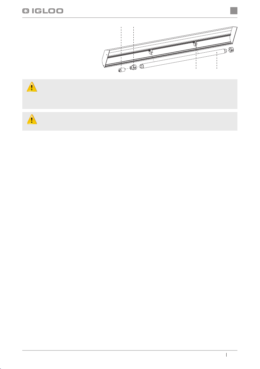
Tabliczka znamionowa znajduje się z tyłu urządzenia,
w prawym, górnym rogu poniżej blatu Rys.1/13 (str.2)
Powyższy rysunek przedstawia poglądową tabliczkę
znamionową, a dane w niej zawarte są danymi przykła-
dowymi nieodnoszącymi się do „Kingi W”!
(Dotyczy term. „CAREL”) Regulator wyświetla E0 lub E1 lub L0 lub HI lub EE lub Ed lub DF zamiast tempe-
ratury:
• E0 -uszkodzenie czujnika temperatury wewnątrz komory- wezwać autoryzowany serwis
• E1 -uszkodzenie czujnika parownika - wezwać autoryzowany serwis
• L0 –alarm niskiej temperatury (niższej niż zadany zakres wewnątrz urządzenia) - wezwać autoryzowany serwis
• HI - alarm wysokiej temperatury - wezwać autoryzowany serwis
• EE -błąd wewnętrzny regulatora - wezwać autoryzowany serwis
• Ed – przekroczenie max. czasu odszraniania
• DF – odszranianie w toku (to nie jest sygnał alarmowy)
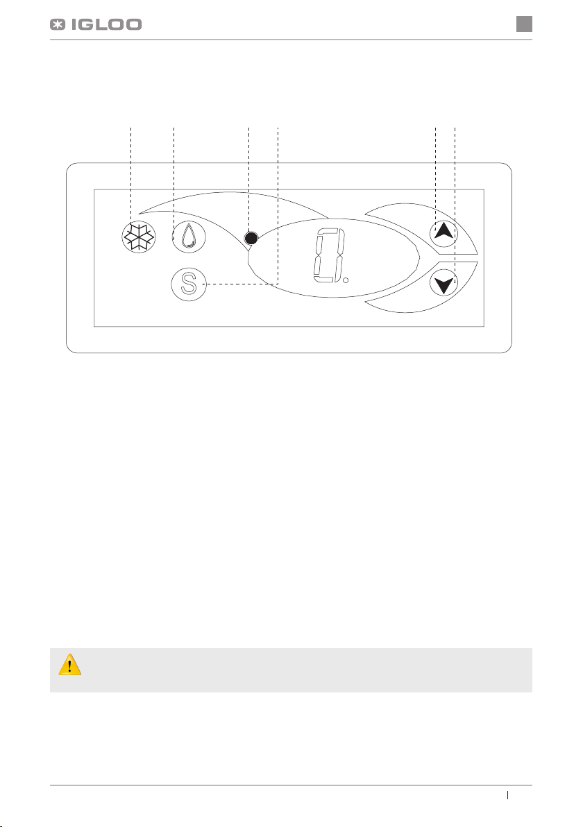
(Dotyczy term. „IGLOO”) Urządzenie pracuje, włączona sygnalizacja dźwiękowa...- Upewnić się, czy
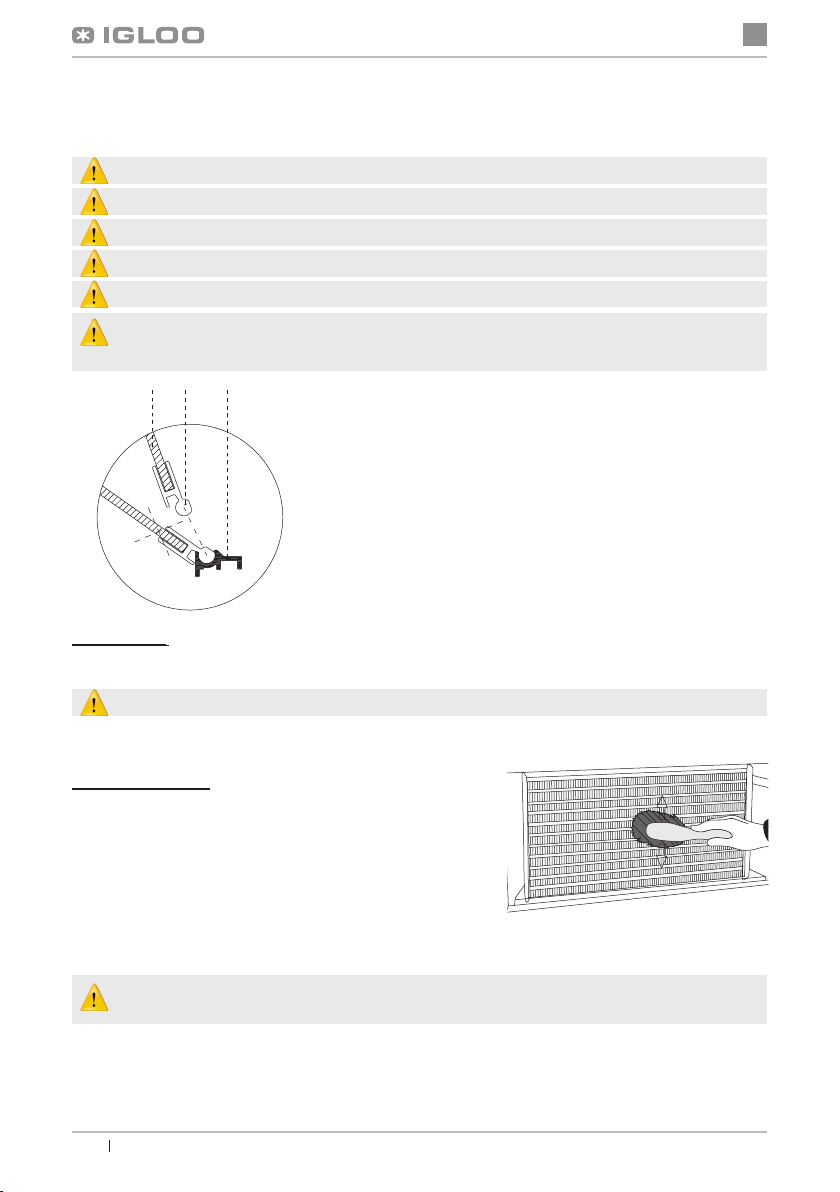
• Skraplacz nie jest zanieczyszczony, w razie potrzeby wyczyścić
• Pracuje wentylator skraplacza
• Temperatura otoczenia nie przekracza 25ºC
Urządzenie pracuje zbyt głośno...- Upewnić się, czy
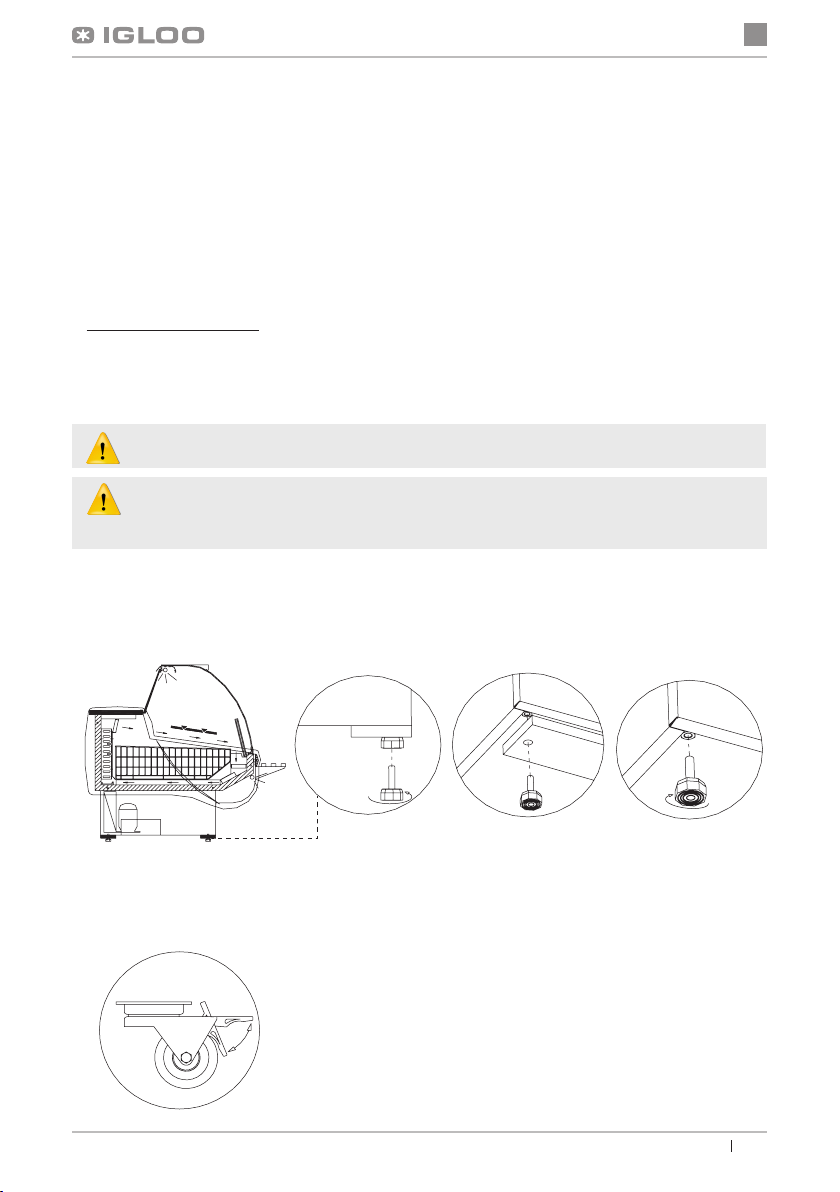
• Urządzenie stoi stabilnie i jest prawidłowo wypoziomowane
• Przylegające do urządzenia meble nie drgają podczas pracy sprężarki agregatu chłodniczego
Rys.11 Tabliczka znamionowa
W przypadku przekroczenia warunków otoczenia wg trzeciej klasy klimatycznej (wilgotność
względna powietrza powyżej 60%) może występować zjawisko przelewania wody z układu z au-
tomatycznym odparowaniem kondensatu (wyparki). Przypadek ten nie oznacza wadliwej pracy
urządzenia i nie wymaga wzywania serwisu.