IKA AOD 1.1 User manual

BETRIEBSANLEITUNG D2
OPERATING INSTRUCTIONS GB 10
MODE D’EMPLOI F18
IKA AOD 1.1
INDICACIONES DE SEGURIDAD E26
VEILIGHEIDSINSTRUCTIES NL 28
NORMI DI SICUREZZA I30
SÄKERHETSANVISNINGAR S32
SIKKERHEDSHENVISNINGER DK 34
SIKKERHEDSHENVISNINGER N36
TURVALLISUUSOHJEET SF 38
Υποδείξεις ασφάλειας
GR 40
INSTRUÇÕES DE SEGURANÇA P42
AOD1.1 18.12.2002 15:16 Uhr Seite 1

2
Mit diesem Symbol sind Informationen gekennzeichnet,
die für die Sicherheit Ihrer Gesundheit von absoluter
Bedeutung sind. Missachtung kann zu Gesundheitsbe-
einträchtigung und Verletzungen führen.
Zeichenerklärung . . . . . . . . . . . . . . . . . . . . . . . . . . . . . . . . . . .2
Inhaltsverzeichnis . . . . . . . . . . . . . . . . . . . . . . . . . . . . . . . . . .2
Sicherheitshinweise . . . . . . . . . . . . . . . . . . . . . . . . . . . . . . . . .2
Lieferumfang AOD 1.1 . . . . . . . . . . . . . . . . . . . . . . . . . . . . . . .4
Öffnen des Aufschlußgefäßes . . . . . . . . . . . . . . . . . . . . . . . . .4
Baumwollfaden befestigen . . . . . . . . . . . . . . . . . . . . . . . . . . .4
Verbrennungen durchführen . . . . . . . . . . . . . . . . . . . . . . . . . .5
Reinigung des Aufschlußgefäßes . . . . . . . . . . . . . . . . . . . . . . .5
Halogene und Aufschluß . . . . . . . . . . . . . . . . . . . . . . . . . . . .5
Pflege und Wartung . . . . . . . . . . . . . . . . . . . . . . . . . . . . . . . . .5
Identifikation des Aufschlußgefäßes . . . . . . . . . . . . . . . . . . . .7
Zubehör . . . . . . . . . . . . . . . . . . . . . . . . . . . . . . . . . . . . . . . . . .8
Technische Daten AOD 1.1 . . . . . . . . . . . . . . . . . . . . . . . . . . .9
Garantie . . . . . . . . . . . . . . . . . . . . . . . . . . . . . . . . . . . . . . . . .9
Ersatzteilbild AOD 1.1 . . . . . . . . . . . . . . . . . . . . . . . . . . . . . . .9
Das Betreiben des Aufschlußgefäßes ist nur in Verbindung mit dem
IKA AOD 1 System zulässig.
Betriebsbedingungen:
Der maximale Energieeintrag in das Aufschlußgefäß darf 30000 J
nicht überschreiten. (Wählen Sie die Probemasse dementsprechend)
Der zulässige Betriebsdruck von 195 bar darf nicht überschritten wer-
den. Die maximal zulässige Betriebstemperatur darf 50°C nicht über-
schreiten.
Füllen Sie das Aufschlussgefäß nicht mit zuviel Probe. Füllen Sie das
Aufschlussgefäß mit Sauerstoff nur bis zu einem Druck von max.
40bar. Kontrollieren Sie den eingestellten Druck am Druckminderer.
Führen Sie vor jeder Verbrennung eine Dichtigkeitsprüfung durch
(siehe Seite 5).
Explosivstoffe:
Manche Stoffe neigen zu einer explosionsartigen Verbrennung (z.B.
aufgrund von Peroxidbildung), die das Aufschlußgefäß zum Bersten
bringen könnten.
Das Aufschlußgefäß AOD 1.1 darf nicht für Untersuchungen an
explosionsfähigen Proben benutzt werden. Für diese Stoffe ist
unbedingt ein spezielles Hochdruckaufschlußgefäß zur
Aufnahme der Probe zu verwenden!
Hinweise zur Probe:
Stoffe, deren Brennverhalten nicht bekannt ist, müssen vor einer
Verbrennung im Aufschlußgefäß AOD 1.1 auf ihr Brennverhalten
untersucht werden (Explosionsgefahr).
Wenn Sie unbekannte Proben verbrennen, verlassen Sie den Raum
oder halten Sie Abstand vom Aufschlussgefäß.
Benzoesäure darf nur in gepresster Form verbrannt werden! Brenn-
bare Stäube und Pulver müssen zuerst gepresst werden.
Ofentrockene Stäube und Pulver wie z.B. Holzspäne, Heu, Stroh usw.
verbrennen explosionsartig! Sie müssen zuerst angefeuchtet werden!
Leicht brennbare Flüssigkeiten mit einem niedrigen Dampfdruck dür-
fen nicht direkt mit dem Baumwollfaden in Berührung gelangen! (z.B.
Tetramethyl-dihydrogendisiloxan)
Zeichenerklärung
Inhaltsverzeichnis
Mit diesem Symbol sind Informationen gekennzeichnet,
die für den einwandfreien Betrieb sowie für den Umgang
mit dem Aufschlußgefäß von Bedeutung sind.
Mißachtung kann ungenaue Meßergebnisse oder
Beschädigungen am Aufschlußgefäß zur Folge haben.
Sicherheitshinweise
AOD1.1 18.12.2002 15:16 Uhr Seite 2

3
stehen, die bei etwa gleicher Beanspruchung hinsichtlich Druck und
Temperatur durchgeführt wird. Versuchsautoklaven müssen in beson-
deren Kammern / Schutzeinrichtung betrieben werden.
Wiederkehrende Prüfungen
Die Aufschlussgefäße sind wiederkehrenden Prüfungen (innere
Prüfungen und Druckprüfungen) durch den Sachkundigen zu unter-
ziehen, deren Zeitpunkt aufgrund der Erfahrungen, der Betriebsweise
und des Beschickungsgutes vom Betreiber festzulegen ist.
Die Garantie wird ungültig, wenn an den Versuchsautoklaven
mechanische Veränderungen vorgenommen werden oder wenn
infolge sehr starker Korrosion (z.B. Lochfraß durch Halogene) die
Festigkeit nicht mehr gewährleistet ist.
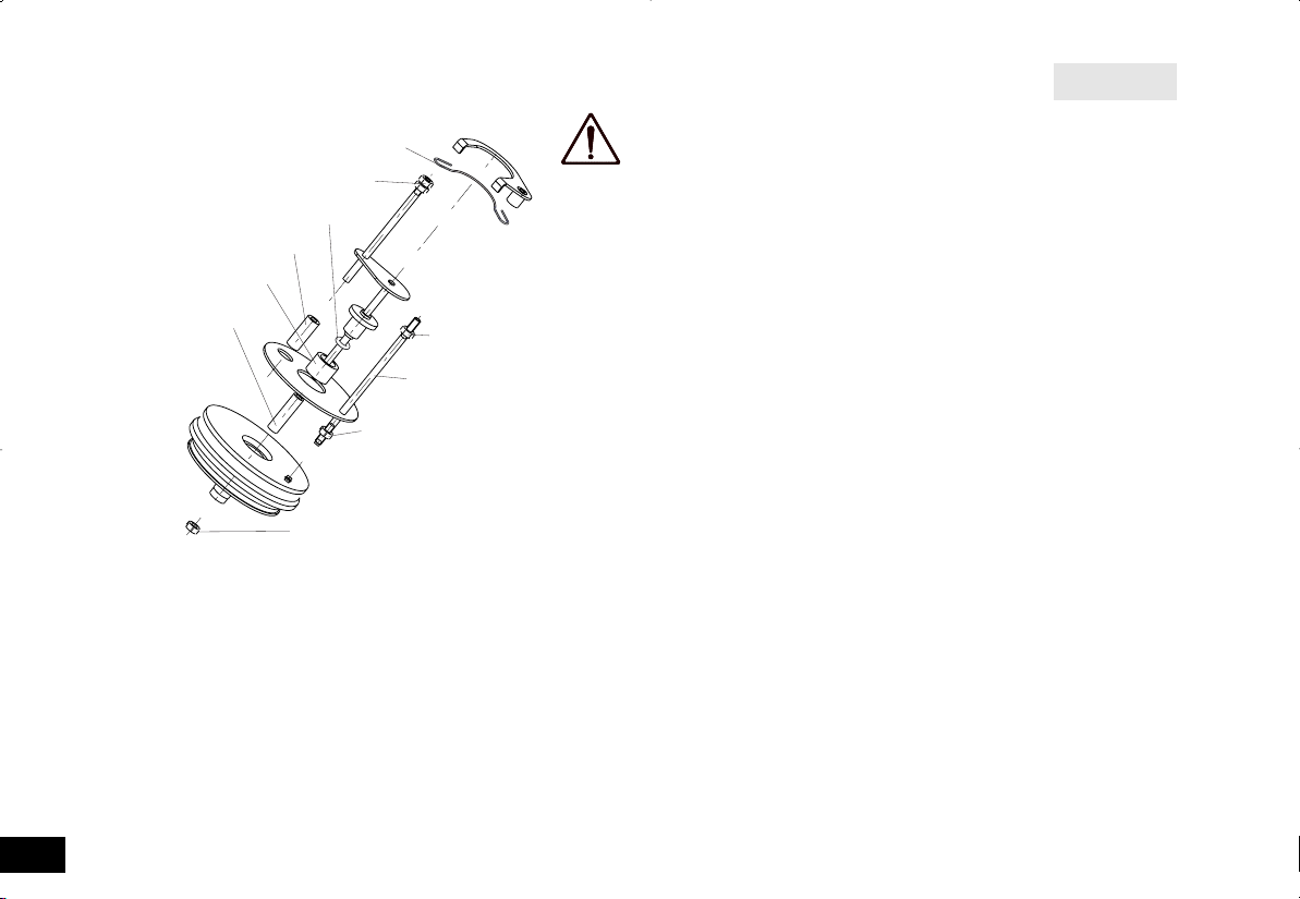
Besonders die Gewinde am Körper des Aufschlussgefäßes und der
Überwurfmutter unterliegen einer hohen Beanspruchung und sind
darum regelmäßig auf Verschleiß zu kontrollieren.
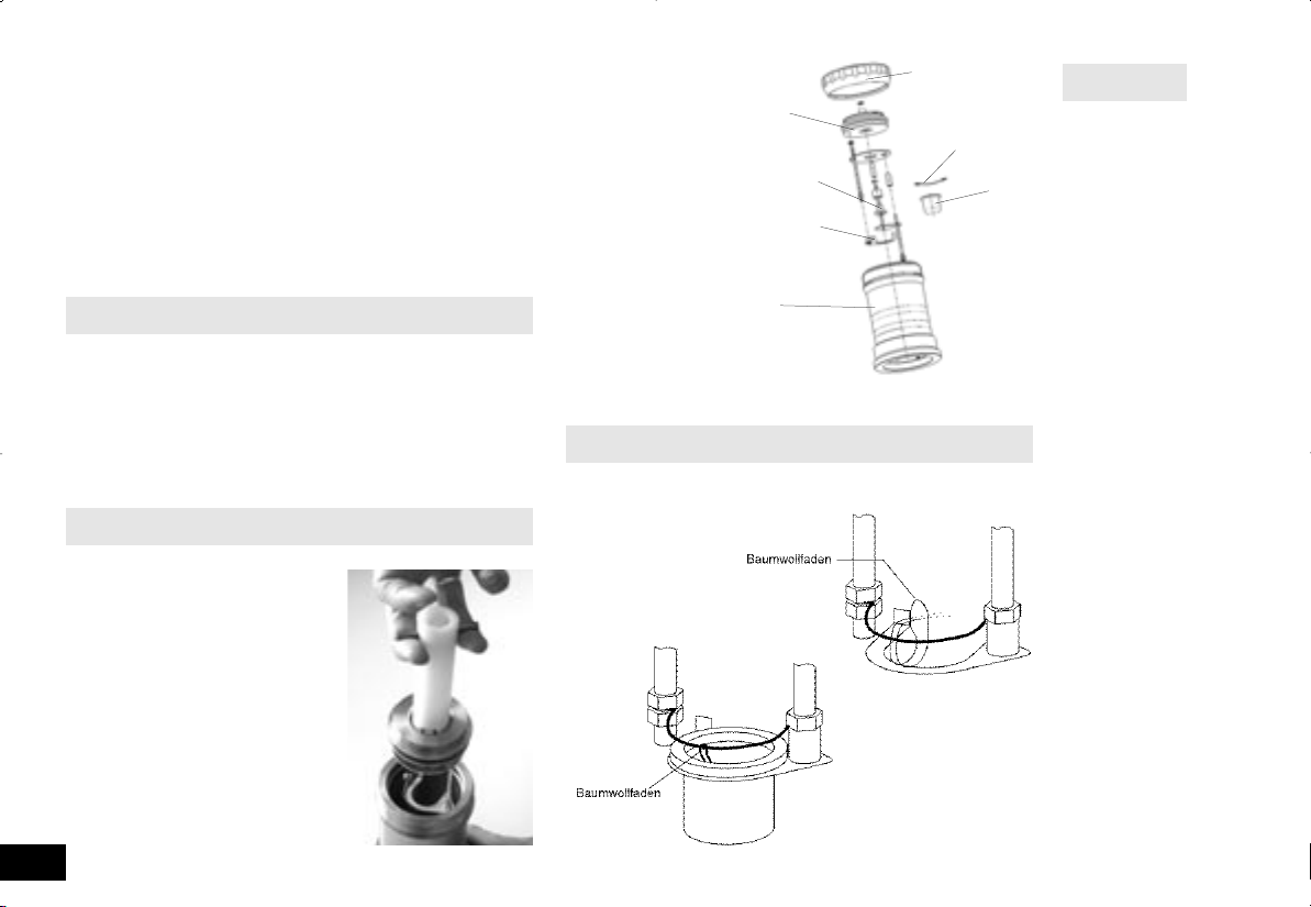
Der Zustand der Dichtungen ist zu kontrollieren und durch eine
Dichtigkeitsprüfung die Funktion sicherzustellen.
(siehe Kap. “Wartung und Pflege; Dichtigkeitsprüfung”)
Druckprüfungen und Servicearbeiten am Aufschlussgefäß dürfen nur
von Sachkundigen vorgenommen werden.
Wir schreiben vor, das Aufschlußgefäß nach jeweils 1000
Versuchen oder nach einem Jahr oder je nach Anwendung auch
früher zur Überprüfung ggf. zur Reparatur in unser Werk einzu-
senden.
Definition Sachkundiger
Sachkundiger im Sinne dieser Betriebsanleitung ist nur, wer
1. auf Grund seiner Ausbildung, seiner Kenntnisse und seiner durch
praktische Tätigkeit gewonnenen Erfahrungen die Gewähr dafür
bietet, dass er die Prüfungen ordnungsgemäß durchführt
2. die erforderliche Zuverlässgkeit besitzt
3. hinsichtlich der Prüftätigkeit keinen Weisungen unterliegt
4. falls erforderlich, über geeignete Prüfeinrichtungen verfügt
5. einen geeigneten Nachweis für die in 1. genannten Vorraus-
setzungen erbringt.
Betrieb von Druckbehältern
Für den Betrieb von Druckbehältern sind die nationalen Richtlinien und
Gesetze zu berücksichtigen!
Verbrennungsrückstände, Hilfsstoffe
Weiterhin sind z.B. toxische Verbrennungsrückstände in Form von
Gasen, Asche oder Niederschlägen an der Innenwand des
Aufschlußgefäßes möglich.
Beachten Sie die für die Tätigkeit und den Arbeitsplatz geltenden
Unfallverhütungsvorschriften. Tragen Sie Ihre persönliche
Schutzausrüstung.
Beim Umgang mit Verbrennungsproben, Verbrennungsrückstän-
den und Hilfsstoffen sind die jeweiligen Sicherheitsvorschriften zu
beachten. Gefahren können z.B. von folgenden Stoffen ausgehen:
ätzenden
leicht entzündlichen
explosionsfähigen
bakteriologisch verseuchten
toxischen
Sauerstoff
Beachten Sie beim Umgang mit Sauerstoff die entsprechenden
Vorschriften.
Gefahrenhinweis: Sauerstoff ist als verdichtetes Gas brandfördernd;
unterstützt intensiv Verbrennungen; kann heftig mit brennbaren Stoffen
reagieren. Kein Öl oder Fett verwenden!
Verwendung von Tiegel aus Edelstahl
Bei Verwendung von Tiegeln aus Edelstahl ist nach jedem Versuch
deren Zustand genau zu kontrollieren.
Durch eine Veringerung der Materialstärke kann der Tiegel verbrennen
und das Aufschlußgefäß AOD 1.1 beschädigen.
Nach max. 25 Verbrennungen dürfen die Tiegel aus Sicherheitsgründen
nicht mehr benutzt werden.
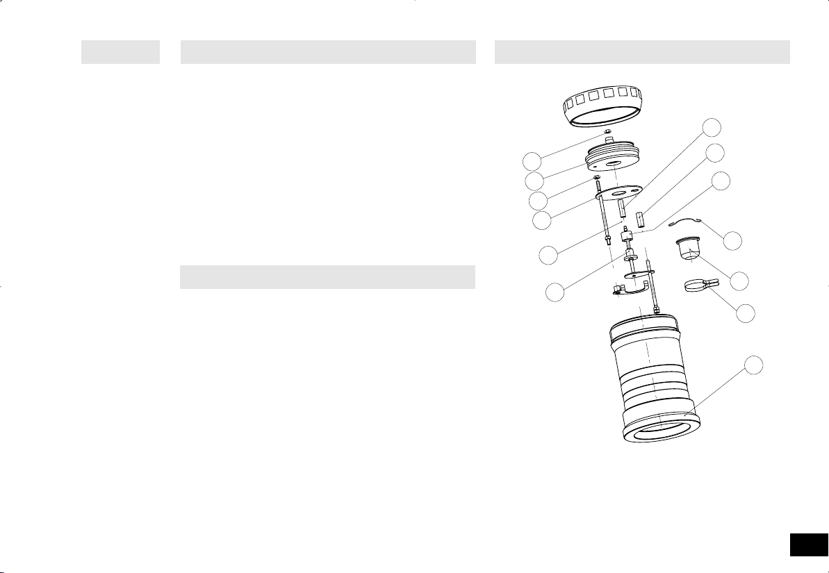
Spezifikation des Aufschlussgefäßes:
Das Aufschlussgefäß wird nach der Richlinie für Druckgeräte 97/23/EG
hergestellt.
Das Aufschlussgefäß wurde einer Druckprüfung mit dem
Prüfdruck von 280 bar und einer Dichtigkeitsprüfung mit Sauerstoff
von 30 bar unterzogen.
Das Aufschlussgefäß AOD 1.1 ist ein Versuchsautoklav und muss
nach jeder Verwendung von einem Sachkundigen geprüft werden.
Unter einer einzelnen Verwendung ist auch eine Versuchsreihe zu ver-
AOD1.1 18.12.2002 15:16 Uhr Seite 3

Wer einen Druckbehälter betreibt, hat diesen in ordnungsgemäßem
Zustand zu halten, ordnungsgemäß zu betreiben, zu überwachen, not-
wendige Instandhaltungs- und Instandsetzungsarbeiten unverzüglich
vorzunehmen und die den Umständen nach erforderlichen
Sicherheitsmaßnahmen zu treffen.
Ein Druckbehälter darf nicht betrieben werden, wenn er Mängel auf-
weist, durch die Beschäftigte oder Dritte gefährdet werden.
Die Druckgeräterichtlinie können Sie im Carl Heymanns Verlag oder
Beuth Verlag beziehen.
1 x Aufschlußgefäß 1 x Betriebsanleitung
1 x Zünddraht 1 x Quarztiegel C 4
1 x O-Ring-Set 1 x Doppelmaulschlüssel SW5,5
1 x C710.4 Baumwollfaden 1 x Sicherungsring
1 x Griff
Überwurfmutter abschrauben
und den Deckel mit Hilfe
des Griffes herausnehmen.
4
Lieferumfang AOD 1.1
Öffnen des Aufschlußgefäßes
Das Aufschluß-
gefäß besteht aus
folgenden Einzel-
teilen:
Das Aufschlußgefäß ist mit einem festen Zünddraht ausgestattet.
Um eine Verbrennung
durchzuführen muß ein
Baumwollfaden am
Zünddraht befestigt
werden.
Baumwollfaden gemäß
Illustration befestigen.
Baumwollfaden befestigen
Überwurfmutter
Tiegelhalter
Deckel
Zünddraht
Tiegel
Aufschluss-
gefäß
elektrischer
Zündkontakt
AOD1.1 18.12.2002 15:16 Uhr Seite 4

5
Für die Vorgehensweise beim Beschicken des Aufschlußgefäßes mit
der Brennstoffprobe und für die generelle Vorgehensweise bei der
Durchführung einer Verbrennung, verweisen wir auf die
Bedienungsanleitung des IKA AOD 1 Systems.
Nach jeder Verbrennung sind alle Teile des Aufschlußgefäßes, die mit
den Verbrennungsprodukten in Berührung kommen, von Kondensat
zu reinigen. Es genügt, die Teile mit einem saugfähigen, nichtfasern-
den Tuch auszuwischen. Verbrennungsrückstände im Tiegel, z.B. Ruß
oder Asche werden auf die gleiche Weise beseitigt. Kann das Auf-
schlußgefäß nicht auf die beschriebene Art gereinigt werden (z.B. auf-
grund von Einbrennungen oder Lochfraß) darf es auf keinen Fall einer
mechanischen Reinigung unterzogen werden.
Bitte setzen Sie sich in solchen Fällen mit Ihrer zuständigen
Servicestelle in Verbindung oder schicken Sie das Aufschlußgefäß zur
Überprüfung und zur Reinigung ins Werk.
Für die quantitative Bestimmung von Halogenen und Schwefel wird
das Aufschlußgefäß AOD 1.1 in konditioniertem Zustand ausgeliefert.
Dies bedeutet, daß die Innenflächen sowie die Armaturen des
Aufschlußgefäßes durch ein patentiertes Verfahren katalytisch akti-
viert wurden.
Die so behandelten Teile sind an ihrer trüben, angelaufenen und
zum Teil fleckigen Oberfläche zu erkennen. Das Aussehen dieser
Oberfläche ist gewollt und darf nicht mit evtl. Gebrauchsspuren
verwechselt werden.
Dieser Zustand ist für die folgende Analytik von großer Wichtigkeit
Reinigen des Aufschlußgefäßes
Verbrennung durchführen
Halogene und Aufschluß
und darf nicht mit Bürsten oder anderen harten Materialien bear-
beitet werden.
Die im folgenden beschriebenen Arbeiten dürfen nur von Sach-
kundigen bzw. von IKA durchgeführt werden.
Alle Arbeiten an den Armaturen des Aufschlußgefäßes erfordern
eine erneute Dichtigkeitsprüfung.
Desweiteren verweisen wir an dieser Stelle noch einmal auf die
Richtlinie für Druckgeräte 97/23/EG.
Auswechseln des Zünddrahtres
Das Aufschlußgefäß AOD 1.1 ist mit einem festen Zünddraht aus-
gestattet. Da dieser während der Verbrennung einer hohen
Materialbeanspruchung unterliegt, sollte er spätestens nach ca.
100 Versuchen ausgetauscht werden. Diese Angabe hängt jedoch
stark von der Art der verbrannten Proben ab.
•Lösen Sie die obere Sechskantmutter (Pos. 11) auf der Zünd-
elektrode (Pos. 5) bzw. Tiegelhalter (Pos. 12) mit einem im
Lieferumfang enthaltenen Doppelmaulschlüssel SW 5,5.
Auswechseln der Zündelektrode
Die Zündelektrode müssen Sie auswechseln, wenn sie durch die
Verbrennungen im Aufschlußgefäß verschlissen ist.
•Öffnen Sie das Aufschlußgefäß wie unter „Öffnen des Auf-
schlußgefäßes“ beschrieben.
•Nehmen Sie die komplette Deckeleinheit in die Hand.
•Entfernen Sie den Zünddraht.
•Lösen Sie die Sechskantmutter Pos. 11 mit Hilfe eines
Doppelmaulschlüssel SW 5,5 gegen den Uhrzeigersinn und halten
dabei die Zündelektrode Pos. 5 fest. Drehen Sie die Sechskant-
mutter vollständig von der Zündelektrode herunter und legen Sie
diese für den Zusammenbau zur Seite.
•Ziehen Sie die Zündelektrode aus dem Deckel heraus. Achten
Sie darauf, daß die Isolierbuchse Pos. 8 und die Lagerbuchse Pos. 9
mit der Elektrode ausgebaut werden. Reinigen Sie beide Teile
nach Bedarf.
Pflege und Wartung
AOD1.1 18.12.2002 15:16 Uhr Seite 5

6
Beim Einsetzen der neuen Elektrode ist ein neuer O-
Ring Pos. 7 zu verwenden.
Wie Sie den O-Ring wechseln,
erfahren Sie weiter unten in die-
sem Kapitel. Achten Sie beim
Zusammenbau darauf, daß
sich keine Schmutzteil-
chen im Deckel befin-
den. Reinigen Sie
deshalb die Dicht-
flächen mit ei-
nem Papier-
tuch.
Der Einbau
erfolgt in um-
gekehrter
Reihenfolge.
•Fädeln
Sie die Iso-
lierbuchse
Pos. 8 und
13, sowie die
Lagerbuchse
Pos. 9 auf die
Zündelek-
trode.
•Setzen Sie die neue Zündelektrode aus dem Elektroden-
Schirmblech-Set Pos. 2002 in den Deckel ein.
•Die Sechskantmutter Pos. 11 wird nur leicht mit dem
Schlüssel festgezogen.
Führen Sie nach dem Zusammenbau des Aufschlußgefäßes eine
Dichtigkeitsprüfung durch.
•Befüllen Sie dazu das Aufschlußgefäß mit Sauerstoff.
Benutzen Sie dazu die Sauerstofffüllstation C48.
•Halten Sie das Aufschlußgefäß mit dem Deckel nach unten in
ein mit Wasser gefülltes Gefäß. Achten Sie darauf, daß das
Aufschlußgefäß maximal bis zur Hälfte eingetaucht werden darf.
•Kontrollieren Sie das Aufschlußgefäß auf austretenden Sauer-
stoff in Form von Blasen.
Die Dichtigkeitsprüfung ersetzt nicht die Druck-
prüfung !
Wartung Sauerstoffventil
Das Sauerstoffventil wird zum Befüllen und Entleeren des
Aufschlußgefäßes benötigt. Es ist ein Rückschlagventil, das erst
schließt, wenn das Aufschlußgefäß mit Sauerstoff befüllt ist. Die
Zündelektrode Pos. 5 dient hier gleichzeitig als Ventilkolben. Die
Dichtfläche sitzt im Deckel des Aufschlußgefäßes.
Die O-Ring-Dichtung verschleißt durch den Gebrauch, sowie
durch aggressive Verbrennungsgase. Dadurch kann das Auf-
schlußgefäß undicht werden.
Kontrollieren Sie in den von den Sicherheitshinweisen vorge-
gebenen regelmäßigen Abständen die Dichtungen auf
Verschleiß. Wird das Aufschlußgefäß während einer
Verbrennung im Kalorimeter undicht, kann der austretende
Sauerstoff das Aufschlußgefäß und das Kalorimeter beschä-
digen.
•Um den O-Ring zu wechseln, muß die Zündelektrode wie
bereits beschrieben, aus dem Deckel ausgebaut werden.
•Entfernen Sie den O-Ring Pos. 7 indem Sie zuerst die
Lagerbuchse Pos. 9 von der Zündelektrode Pos. 5 abziehen und
danach den O-Ring entfernen.
•Setzen Sie den neuen O-Ring von oben auf die Zündelektrode
Pos. 5 auf und schieben danach die Lagerbuchse Pos. 9 bis zum
Absatz wieder auf die Zündelektrode Pos. 5 auf.
Achten Sie hier besonders darauf, daß der O-Ring nicht durch
scharfe Kanten beschädigt wird.
Die Lagerbuchse Pos. 9 wird durch die Sechskantmutter Pos. 11
nach dem Einbau der Zündelektrode gegen Verschieben gesichert.
8
13
9
12
31
11
11
11
11
7
☞
AOD1.1 18.12.2002 15:16 Uhr Seite 6

•Entfernen Sie Zünddraht und Zündelektrode wie zuvor
beschrieben.
•Lösen Sie gegen den Uhrzeigersinn die an der Deckelinnen-
seite anliegende Sechskantmutter des Tiegelhalters mit dem
Doppelmaulschlüssel SW5,5.
•Schrauben Sie den Tiegelhalter aus dem Deckel heraus.
Der Einbau des neuen Tiegelhalters erfolgt in umgekehrter
Reihenfolge. Bevor Sie die Sechskantmutter wieder festziehen,
müssen Sie den Tiegelhalter entsprechend der Abbildung Seite 6
ausrichten. Die Sechskantmutter wird nur leicht mit dem
Schlüssel festgezogen.
Die Einzelteile des Aufschlußgefäßes sind durch die eingravierte
Fabrikationsnummer und die technischen Daten eindeutig ge-
kennzeichnet. Die Angaben entsprechen der Richtlinie für
Druckgeräte.
Die Einzelteile mehrerer Aufschlußgefäße (Deckel, Überwurfmut-
ter und Unterteil) dürfen nicht untereinander ausgetauscht wer-
den. Bei Beschädigung eines der genannten Teile, muß das kom-
plette Aufschlußgefäß zur Prüfung ins Werk eingeschickt werden.
Wechsel der Hauptdichtung
Die Hauptdichtung Pos. 4 dient zum Abdichten des Deckels Pos.
2 gegenüber dem Unterteil Pos. 1.
Die Hauptdichtung sowie die Dichtfläche am Unterteil muß vom
Sachkundigen nach jeder Verbrennung auf Verschleiß kontrolliert
werden. Ist Verschleiß zu erkennen, muß die Hauptdichtung aus-
gewechselt werden.
•Die Hauptdichtung Pos. 4 entfernen Sie indem Sie mit einem
geeigneten Werkzeug den O-Ring aus der Nut im Deckel Pos. 2
heraushebeln.
•Ziehen Sie den O-Ring auf die im Durchmesser kleinere Seite
des Deckels herunter.
Achten Sie darauf, daß Sie mit dem Werkzeug den Deckel nicht
beschädigen. Dies kann dazu führen, daß das Aufschlußgefäß
undicht wird. Die alte Dichtung darf nicht wiederverwendet wer-
den. Ersetzen Sie die alte Dichtung.
•Die neue Dichtung wird ebenfalls von der im Durchmesser
kleineren Seite aufgezogen. Legen Sie den O-Ring auf einer Seite
in die Nut im Deckel.
•Ziehen Sie den O-Ring mit den Fingern über den Deckelrand
bis er selbstständig in die Nut einschnappt.
Führen Sie nach dem Zusammenbau des Aufschlußgefäßes eine
Dichtigkeitsprüfung durch.
•Befüllen Sie dazu das Aufschlußgefäß mit Sauerstoff. Benut-
zen Sie dazu die Sauerstoffstation C 48.
•Halten Sie das Aufschlußgefäß mit dem Deckel nach unten in
ein mit Wasser gefülltes Gefäß.
•Kontrollieren Sie das Aufschlußgefäß auf austretenden
Sauerstoff in Form von Blasen.
Die Dichtigkeitsprüfung ersetzt nicht die
Druckprüfung !
Tiegelhalter wechseln
Den Tiegelhalter müssen Sie auswechseln, wenn er durch die Ver-
brennungen im Aufschlußgefäß verschlissen ist.
•Öffnen Sie das Aufschlußgefäß wie unter „Öffnen des Auf-
schlußgefäßes“ beschrieben.
7
Identifikation des Aufschlussgefäßes
Überwurfmutter
Deckel
Unterteil
Typ
Prüfdatum Seriennummer
AOD1.1 18.12.2002 15:16 Uhr Seite 7

C14
C5010.4
Entlüftungsgriff C 7010.8
Quarzschälchen C 4
Zünddrähte (2 Stck) C 5012.3
Baumwollfäden (500 Stck) C 710.4
Gelatinekapseln (100 Stck) C 9
Acetobutyratkapseln (100 Stck) C 10
Benzoesäure (NBS) (30 g) C 43
Benzoesäure (100 g) C 43A
Benzoesäure tablettiert (50 Stck) C 723
Verbrennungstütchen 40x35 (100 Stck) C 12
Verbrennungstütchen 70x40 (100 Stck) C 12A
Einwegtiegel C 14
Auflage C 5010.4
Weiteres Zubehör finden Sie auch im IKA-Katalog. Die Adresse
finden Sie auf der Rückseite dieser Betriebsanleitung.
Verwendung von Einwegtiegeln
Für das Aufschlussgefäß AOD 1.1 sind Einwegtiegel erhältlich.
Diese Einwegtiegel C14 erleichtern und verkürzen
die
Vorbereitung einer Verbrennung. Sie bestehen aus einem trans-
parenten Kunststoff, der vollständig zu CO2und H2O verbrennt.
Vorteile:
•Die Probe kann direkt in den Einwegtiegel eingewogen werden.
•Das Gewicht der Einwegtiegel C14 kann von der Waage, zur
Berechnung der Fremdenergie, an das Kalorimeter übergeben
werden.
•Es wird kein Baumwollfaden mehr benötigt.
•Der Einwegtiegel C14 ist eine Brennhilfe. Proben die im norma-
len Tiegel unvollständig verbrennen, werden mit dem Einweg-
tiegel C14 besser verbrannt. Dadurch werden bessere Messer-
gebnisse erzielt.
8
Zubehör Auswechseln der Tiegelhalterung
Für die Verwendung des Einwegtiegels
C14 muss in das Aufschlussgefäß
AOD 1.1die Auflage C 5010.4 ein-
gesetzt werden.
Diese Auflage C 5010.4 ersetzt die
normale Tiegelhalterung.
Nehmen Sie die Deckeleinheit und lösen
Sie wie bereits beschrieben den Zünddraht
am Tiegelhalter.
Schrauben Sie die Tiegel-
halterung vom Schaft her-
unter und ersetzen Sie diese
gegen die Auflage C 5010.4.
Einsetzen des Einwegtiegel C14
Der Einwegtiegel C14 muss so
in die Tiegelhalterung der Auf-
lage C 5010.4 eingesetzt wer-
den, dass der Zünddraht den
Einwegtiegel C14 berührt. Am
besten wird er unter den Zünd-
draht geklemmt.
C 5010.4
AOD1.1 18.12.2002 15:16 Uhr Seite 8

Betriebsdruck max. 195 bar
Prüfdruck 280 bar
Volumen 210 ml
Kerntemperaturen ≥1300 °C
Betriebstemperatur max. 50°C
Probenaufschluß isochor
Sauerstoffventil Rückschlagventil
(kein Vakuumbetrieb möglich)
Tiegelhalter
Produktberührendes Material
Unterteil
Deckel
Verschraubung
n. DIN 51 900
2.4610.40
2.4610.40
1.4439
Sie haben ein Original IKA-Laborgerät erworben, das in Technik und
Qualität höchsten Ansprüchen gerecht wird.
Entsprechend den IKA - Verkaufs- und Lieferbedingungen beträgt die
Garantiezeit 24 Monate. Im Garantiefall wenden Sie sich bitte an Ihren
Fachhändler. Sie können aber auch das Gerät unter Beifügung der
Lieferrechnung und Nennung der Reklamationsgründe direkt an unser
Werk senden. Frachtkosten gehen zu Ihren Lasten.
9
Technische Daten AOD 1.1 Ersatzteilbild AOD 1.1
11
11
4
12
32
7
5
13
9
8
31
30
14
Pos. 4 O-Ring
Pos. 5 Elektrode C7011FZ
Pos. 7 O-Ring 4 x 1,5
Pos. 8 Isolierbuchse
Pos. 9 Lagerbuchse
Pos.11 Sechskt. Mutter M3
Pos. 12 Schalenträger
Pos. 13 Isolierbuchse
Pos. 14 Distanzring
Pos. 30 Sicherungsring
Pos. 31 Zünddraht C5010
Pos. 32 Quarzschälchenl C4
Garantie
AOD1.1 18.12.2002 15:16 Uhr Seite 9

10
This symbol identifies information that is absolutely
essential for your safety and health. Failure to obser-
ve this information may result in negative effects for
your health and injuries.
Explanation of symbols . . . . . . . . . . . . . . . . . . . . . . . . . . . . .10
Contens . . . . . . . . . . . . . . . . . . . . . . . . . . . . . . . . . . . . . . . . .10
Safety Instructions . . . . . . . . . . . . . . . . . . . . . . . . . . . . . . . . .10
Included with delivery AOD 1.1 . . . . . . . . . . . . . . . . . . . . . . .12
Opening the decomposition vessel . . . . . . . . . . . . . . . . . . . .12
Fastening cotton thread . . . . . . . . . . . . . . . . . . . . . . . . . . . . .12
Combustion procedure . . . . . . . . . . . . . . . . . . . . . . . . . . . . .13
Cleaning the decomposition vessel . . . . . . . . . . . . . . . . . . . .13
Halogens and decomposition . . . . . . . . . . . . . . . . . . . . . . . . .13
Care and maintenance . . . . . . . . . . . . . . . . . . . . . . . . . . . . . .13
Decomposition vessel identification . . . . . . . . . . . . . . . . . . . .15
Accessories . . . . . . . . . . . . . . . . . . . . . . . . . . . . . . . . . . . . . .16
Technical data for AOD 1.1 . . . . . . . . . . . . . . . . . . . . . . . . . .17
Guarantee . . . . . . . . . . . . . . . . . . . . . . . . . . . . . . . . . . . . . . .17
Spare parts diagram for theAOD 1.1 . . . . . . . . . . . . . . . . . . .17
Operation of decomposition vessels is only permitted in combi-
nation with the AOD 1 system.
Operating requirements:
The maximum amount of energy input into the decomposition
vessel must not exceed 30000 J. (Select the weight of the sam-
ple accordingly). The permissible operating pressure of 195 bar
must not be exceeded. The maximum permissible operating
temperature must not exceed 50 ° C.
Do not fill the decomposition vessel too full of the sample. Only
fill the decomposition vessel with oxygen up to a maximum pres-
sure of 40 bar. Monitor the adjusted pressure on the pressure
reducer. Perform a check before every combustion to ensure
there are no leaks (see page 13).
Explosive substances:
Many substances tend to combust in an explosive manner (for
example because of the formation of peroxide). This may cause
the decomposition vessel to burst.
The AOD 1.1 decomposition vessel must not be used for
examinations on samples that are capable of exploding. It is
absolutely essential to use a special high-pressure decom-
position vessel to contain the sample in these cases!
Notes on the sample:
Substances of which the combustion behavior is not known
must be examined for their combustion behavior before combu-
stion in the decomposition vessel AOD 1.1 (danger of explosion).
If you are burning unknown samples, leave the room or keep a
safe distance between you and the calorimeter.
Benzoic acid must only be burned in the form of pellets!
Combustible dust and powder must be compressed into pellets
before combustion. Oven-dry dust and powder such as wood
chips, hay, straw, etc. burn in an explosive manner! They must be
moistened first! Readily combustible liquids with a low vapor pres-
sure must not be come in direct contact with the cotton thread (for
example tetramethyl dihydrogen disiloxan)!
Explanation of symbols
Contents
This symbol identifies information that is important for
problem-free operation as well as for working with the
decomposition vessel. Failure to observe these
instructions may result in inaccurate measurement
results or damage to the decomposition vessel.
Safety Instructions
AOD1.1 18.12.2002 15:16 Uhr Seite 10

must be operated in special chambers / protectiv device.
Repeated tests
The decomposition vessel must be subject to repeated tests
(internal tests and pressure tests) by a person with professional
training. The intervals between tests must be determined by the
operator based on experience, operating manner and the material
used in the decomposition vessel.
The guarantee loses its validity if mechanical modifications
are made to the experiment autoclaves or if stability can no
longer be guaranteed as a result of heavy corrosion (for exam-
ple holes eaten in it by halogens).
The threading on the body of the decomposition vessel and cap
screw in particular are subject to a high level of mechanical stress
and must therefore be monitored regularly for wear and tear.
The condition of the seals must be checked for functionality must
be ensured by means of a test for leaks.
(see the sections entitled ”Care and maintenance; Leak test”)
Pressure tests and service tasks on the decomposition vessel
must only be performed by persons with professional training.
We recommend that the decomposition vessel be sent
into
our factory for inspection and repairs if necessary after
either 1000 experiments or after one year or, depending on
the application, even sooner than this.
Definition of person with professional training
A person with professional training as defined in these operating
instructions is someone
1. whose training, knowledge and experience gained through
practical activities ensures that that person will perform the tests
in a proper manner.
2. who is sufficiently reliable
3.
who is not subject to any instructions in terms of testing activity
4. who is equipped with suitable testing equipment if necessary
5. who can provide suitable proof demonstrating compliance with
the requirements listed in 1.
Operating pressure containers
National regulations and laws for operating pressure containers
must be observed!
11
Combustion residue, auxiliary materials
In addition, toxic residues of combustion are possible in the form
of gasses, ash or precipitates on the inner wall of the decomposi-
tion vessel, for example.
Observe the accident prevention requirements applicable to
the activity and the work station. Wear personal safety equip-
ment.
When handling combustion samples, combustion residues and
auxiliary materials, the appropriate safety requirements must be
observed. The following are examples of substances that may
cause dangers:
corrosive, easily flammable, capable of exploding
contaminated with bacteria, toxic
Oxygen
When working with oxygen, observe the appropriate require-
ments.
Danger warning: As a compressed gas, oxygen promotes combu-
stion, supports combustion intensively and may react violently
with combustible substances. Do not use any oil or grease!
Using a crucible made of stainless steel
When using crucibles made of stainless steel, their condition
should be carefully checked after every experiment.
A reduction in the thickness of the material may cause the crucible
to burn and may damage the AOD 1.1 decomposition vessel.
For reasons of safety, crucibles must not be used any more after
a maximum of 25 combustion procedures.
Specification of the decomposition vessel:
The decomposition vessel is manufactured in accordance with the
regulation for pressure vessels 97/ 23/ EC. The decomposition
vessel has been subjected to a pressure test at a test pressure of
280 bar and a leak test with oxygen at 30 bar.
The AOD 1.1 decomposition vessel is an experiment autoclave
and must be tested by a professionally trained person each time
before they are used.
An individual application is understood here to mean a series of
experiments that are performed under roughly the same conditi-
ons in terms of pressure and temperature Experiment autoclaves
AOD1.1 18.12.2002 15:16 Uhr Seite 11

12
Anyone who operates a pressure container must maintain it in pro-
per condition, must monitor it and perform necessary maintenan-
ce and repair tasks without delay, and must take measures appro-
priate for the circumstances to ensure safety.
A pressure container must not be operated if it exhibits defects
that could endanger those working with it or third parties.
You can obtain a copy of the pressure vessel regulation from Carl
Heymann Press or Beuth Press.
1 x decomposition vessel 1 x operating instructions
1 x ignition wire 1 x C 4 combustion crucible
1 x O-ring set 1 x SW5,5 double open ended wrench
1 x C710.4 cotton threat 1 x
snap ring
1 x grip
Unscrew union nut and use
the handle in order
to pull out the cover.
Unscrew union nut
and use the handle
in order to pull out
the cover.
The decomposition vessel is equipped with a fixed ignition wire.
A cotton thread has to
be fastened to the igni-
tion wire in order to
carry out combustion.
Fasten cotton thread as
shown in the diagram.
Included with delivery of AOD 1.1
Opening the decomposition vessel
Union nut
Crucible
holder
Cover
Ignition wire
Crucible
Decomposi-
tion vessel
Electrical
ignition wire
Fastening cotton thread
Cotton thread
Cotton thread
AOD1.1 18.12.2002 15:16 Uhr Seite 12

13
For the decomposition vessel charging procedure with fuel sam-
ples and the general procedure for performing combustion plea-
se refer to the operating instructions for the IKA AOD 1 system.
After each combustion the condensate has to be cleaned from
all of the parts of the decomposition vessel which come into
contact with the combustion products. It suffices to wipe out
the parts with an absorbent, non-fibrous cloth. Combustion
residues in the crucible, e.g. carbon black or ash are removed
in the same manner. The decomposition vessel may not be
mechanically cleaned under any circumstances if it is not capa-
ble of being cleaned in the manner described (e.g. due to burn-
in or pitting).
In such cases please contact your competent service center or
send in the decomposition vessel to the factory for inspection
and cleaning.
Decomposition vessel AOD 1.1 is obtainable in a modified
form for determining halogens and sulfur. This means that the
inner surfaces and the fittings of the decomposition vessel are
catalytically activated by means of a patented procedure.
Parts thus treated are recognizable because of their opaque, tar-
nished and partly spotty surfaces. This appearance of this surfa-
ce is intentional and should not be confused with traces of wear.
This state is important for the following analysis and may not
be treated with brushes or other hard materials.
The work described in the following may only be performed by
personnel with professional training or IKA.
All work on the fittings of the decomposition vessel require a
leak test and new pressure testing.
Furthermore, reference is made to the regulation for pressure
vessels 97/23/EC.
Replacing the ignition wire
The AOD 1.1 decomposition vessel is equipped with a fixed igni-
tion wire. Since the ignition wire is subjected to a high degree of
material stress during combustion, it should be replaced after
about 100 tests at the latest. However, this largely depends on
the type of samples fired.
•Unscrew the upper hexagonal nut (item 11) on the ignition
electrode (item 5) or the crucible holder (item 12) using a double
open ended spanner SW 5,5 which is included in the delivery
quantity.
Replacing the ignition electrode
The ignition electrode has to be replaced if it has become worn
as a combustion in the decomposition vessel.
•Open the decomposition vessel as described under
„Opening the decomposition vessel“.
•Take hold of the complete cover unit.
•Remove the ignition wire
•Unscrew the hexagonal nut (item 11) in a counterclockwise
direction using the double open ended spanner (SW 5,5) while
firmly holding the ignition electrode (item 5). Screw the hexago-
nal nut completely off of the ignition electrode and put it aside for
later assembly.
•Pull the ignition electrode out of the cover. Make certain that
the insulating bushing (item 8) and the bearing bush (item 9) are
removed with the electrode. Clean both parts if required.
Combustion procedure
Cleaning the decomposition vessel
Halogens and decomposition
Care and maintenance
AOD1.1 18.12.2002 15:16 Uhr Seite 13

A new o-ring (item 7) should be used when the new
electrode is inserted.
Information on how to replace the
0-ring is provided further on in
this chapter. Make certain
that there are no dirt par-
ticles in the cover when
reasembling the unit.
Use a paper towel
to clean the sea-
ling surfaces.
Installation is
performed in
the reverse
order.
•Put the
rate insula-
ting bushing
(item 8 and
13) and the
bearing bus-
hing (item 9)
on to ignition
electrode.
•Insert
the new ignition electrode contained in the set of electrodes with
deflector (item 2002) into the cover.
•The hexagonal nut (item 11) should only be slightly tightened
with the spanner.
A leak test should be performed after assembly of the decom-
position vessel has been completed.
•Fill the decomposition vessel with oxygen. Use the C 48
oxygen station in order to do so.
•Hold the decomposition vessel with the cover upside down
in a vessel that is completely filled with water.
Be careful to only immerse only half of the decomposition vessel
at most.
•Check the decomposition vessel for escaping bubbles of
oxygen.
The leak test does not replace pressure testing !
Oxygen valve maintenance
The oxygen valve is used to fill and emptycthe decomposition
vessel. It is a non-returnable valve that only closes when the
decomposition vessel is full with oxygen.
The ignition electrode (item 5) serves at the same time as a valve
piston. The sealing surface is in the cover of the decomposition
vessel. The O-ring sealing wears through use and because of
aggressive combustion gases, which means that the decompo-
sition vessel may not be tight.
Check the sealings for wear in accordance with regular inter-
vals stipulated by the safety provisions. If the decompositi-
on leaks during combustion in the calorimeter the escaping
oxygen may damage the decomposition vessel and the calo-
rimeter.
•In order to replace the O-ring the ignition electrode must be
removed from the cover as described.
•Remove the O-ring (item 7) by first pulling the bearing bus-
hing (item 9) off of the ignition electrode and then removing the
O-ring.
•Place the new O-ring from the set of O-rings onto the igniti-
on electrode (item 5) from above and then push the bearing bus-
hing (item 9) until it again reaches the ignition electrode.
Make certain that the O-ring does not become damaged by
sharp edges.
After installation of the ignition electrode the bearing bushing is
teightened with the hexagonal nut (item 11) in order to prevent
it from slipping out of place.
14
8
13
9
12
31
11
11
11
11
7
☞
AOD1.1 18.12.2002 15:16 Uhr Seite 14

15
Replacing the main seeling
The main sealing (item 4) is used to seal off the cover (item 2)
from the bottom part (item 1).
The main sealing and the sealing surface on the bottom part
must be checked for wear by an expert after each combustion
operation. The main sealing must be replaced if wear is evident.
•Remove the main sealing (item 4) by using a suitable tool to
pry the O-ring out of the groove in the cover (item 2).
•Pull the O-ring toward the side of the cover that is smaller in
diameter.
Make certain not to damage the cover with tool. This may cause
the decomposition vessel to leak. The sealing that has thus been
replaced may not be reused. Replaced the old sealing with a new
one from the set of O-rings.
•The new sealing is also mounted on the side of the cover
that is smaller in diameter. Place the O-ring on one side the groo-
ve in the cover.
•Use your fingers to pull the O-ring over the edge of the cover
until it snaps into groove on its own.
Perform a leak test after the decomposition vessel has been
assembled.
•Fill the decomposition vessel with oxygen (C 48).
•Hold the decomposition vessel with the cover upside down
in a vessel that is filled with water.
•Check the decomposition vessel for escaping bubbles of oxy-
gen.
The leak test does not replace pressure testing !
Replacing the crucible holder
The crucible holder must be replaced it if has become worn as a
result of the combustion operations.
•Open the decomposition vessel as described under
„Opening the decomposition vessel“.
•Remove ignition wire and ignition electrode as discribed
before.
•Unscrew the hexagonal nut adjacent to the inside cover of
the crucible holder in a counterclockwise direction using the SW
5,5 double open ended spanner.
•Screw the crucible holder out of the cover.
Installation of the new crucible holder is performed in the rever-
se order. The crucible holder has to be aligned (see page 14)
before tightening the hexagonal nut (item 14). The hexagonal
nut is tightened only slightly with the spanner.
The individual parts of the decomposition vessel are clearly iden-
tified by means of the engraved serial number and the technical
data. The data is in accordance with the regulation for pressure
device.
The individual parts of several decomposition vessels (cover, cap
screw and bottom part) are not interchangeable.
If one of the
parts indicated becomes damaged then the complete decomposi-
tion vessel has to be sent to the factory for testing.
Decomposition vessel identification
Union nut
Cover
Upper part
Typ
Proof date
Seriel number
AOD1.1 18.12.2002 15:16 Uhr Seite 15

C14
C5010.4
Venting handle C 7010.8
Quartz crucible C 4
Ignition wire (5 pieces) C 5012.3
Cotton threads (500 pieces) C 710.4
Gelatin capssules (100 pieces) C 9
Acetobutyrate capsules (100 pieces) C 10
Benzoic acid (NBS) (30 g) C 43
Benzoic acid (100 g) C 43A
Benzoic acid tablets (50 pieces) C 723
Combustion bags 40x35 (100 pieces) C 12
Combustion bags 70x40 (100 pieces) C 12A
Oneway crucible C 14
Foundation C 5010.4
Other accessories can also be found in our IKA-Catalogue. The
adress is included on the back of these operating instructions.
Use of oneway crucible
For the decomposition vessels AOD 1.1 are oneway crucibles C14
ease and shorten the preparation of combustion. They consist of
a transparent plastik which burns completely to CO2and H2O.
Advantages:
•The sample can be directly weighted in the oneway crucible.
•The weight of the oneway crucible C14 can be delivered from
the weighing-machine to the calorimeter for the caculate the
foreign energy.
•There’s no more need for an cotton thread.
•The one way crucible C14 is a burning help. Samples burning
incomplete in normal crucibles are burned better with the one
way crucible C14. Thgere by better measuring results are rea-
ched.
16
Accessories
Replacing of the crucible holder
For the use of the oneway crucible
C14 the decomposition vessels
AOD 1.1 must be put in the
foundation C 5010.4.
This foundation C 5010.4 replaces
the normal crucible holding.
Take thecover part and until the ignition
wire on the crucible holder like
discribed before.
Screw down the cru-
cible holder from the
shaft and replace it with
the foundation
C 5010.4.
Installation of the oneway crucible C14
The oneway crucible C14 must
be put into the crucible holding
of the foundation C 5010.4 so
that the ignition wire touches
the oneway crucible C14.
It would the best to stick it
under the ignition wire.
C 5010.4
AOD1.1 18.12.2002 15:16 Uhr Seite 16

17
Operating pressure max. 195 bar
Test pressure 280 bar
Volume 210 ml
Nuclear temperatures ≥1300 °C
Operation temperatures max. 50°C
Sample decomposition isochor
Oxygen valve non-returnable valve
(Vacuum operation not possible)
Crucible holder as in DIN 51 900
Material in contact with the product
Lower part 2.4610.40
Cover 2.4610.40
Threated joint 1.4439
You have purchased an original IKA laboratory machine which
meets the highest engineering and quality standards.
In accordance with IKA guarantee conditions, the guarantee
period is 24 months. For claims under the guarantee please
contact your local dealer.
You may also send the machine direct to our works, enclosing
the delivery invoice and giving reasons for the claim. You will
be liable for freight costs.
Guarantee
Technical data AOD 1.1 Spare parts diagram for AOD 1.1
11
11
4
12
32
7
5
13
9
8
31
30
14
Pos. 4 O-ring
Pos. 5 electrode C7011FZ
Pos. 7 O-ring 4 x 1,5
Pos. 8 insulating bushing
Pos. 9 bearing bushing
Pos.11 hexagonal nut M3
Pos. 12 dish holderr
Pos. 13 insulating bushing
Pos. 14 distance ring
Pos. 30 securing ring
Pos. 31 ignition wire C5010
Pos. 32 quart crucible C4
AOD1.1 18.12.2002 15:16 Uhr Seite 17

18
Ce symbole est placé devant des informations qu’il
est capital de respecter pour protéger la santé. Un
non-respect peut affecter la santé et conduire à des
blessures.
Explication des symboles . . . . . . . . . . . . . . . . . . . . . . . . .18
Sommaire . . . . . . . . . . . . . . . . . . . . . . . . . . . . . . . . . . . .18
Consgnes de sécurité . . . . . . . . . . . . . . . . . . . . . . . . . . .18
Matérial fourni avec le AOD 1.1 . . . . . . . . . . . . . . . . . . . .20
Ouverture de la bombe calorimétrique . . . . . . . . . . . . . . .20
Fixation de la mèche en coton . . . . . . . . . . . . . . . . . . . . .20
Réalisation de la combustion . . . . . . . . . . . . . . . . . . . . . .21
Nettoyage de la bombe calorimétrique . . . . . . . . . . . . . . .21
Halogènes et combustion . . . . . . . . . . . . . . . . . . . . . . . . .21
Soin et entretien . . . . . . . . . . . . . . . . . . . . . . . . . . . . . . .21
Identification de la bombe calorimétrique . . . . . . . . . . . . .23
Accessoires . . . . . . . . . . . . . . . . . . . . . . . . . . . . . . . . . . .24
Caractéristiques techniques AOD 1.1 . . . . . . . . . . . . . . . .25
Garantie . . . . . . . . . . . . . . . . . . . . . . . . . . . . . . . . . . . . . .25
Pièces d’étachées AOD 1.1 . . . . . . . . . . . . . . . . . . . . . . .25
Les bombes ont seulement le droit d’être utilisées en combi-
naison avec les modèles de AOD 1 système.
Conditions d’utilisation :
L’énergie maximale apportée à la bombe ne doit pas dépasser
3000 J. (Sélectionner la masse d’échantillon en conséquence).
La pression de service ne doit pas excéder 195 bars. La
température de service est limitée à 50°C.
Ne pas verser une trop grande quantité d’échantillon dans la
bombe. Remplir le récipient d’oxygène seulement jusqu’à une
pression de 40 bars au maximum. Contrôler la pression réglée
au réducteur de pression.
Vérifier l’étanchéité avant toute combustion (voir page 21)
Substances explosives :
Certaines matières tendent à brûler de façon explosive (par ex.
en raison de la formation de péroxyde), ce qui peut faire écla-
ter la bombe.
Les bombes calorimétriques AOD 1ne sont pas conçues
pour l’examen d’échantillons explosifs. L’analyse de telles
substances nécessite l’emploi d’une bombe spéciale haute
pression !
Remarques sur les échantillons :
Il est nécessaire de déterminer, avant la combustion dans les
bombes AOD 1.1, le comportement à la combustion d’échan-
tillons pour lesquels cette caractéristique n’est pas connue (ris-
que d’explosion).
Si on brûle des échantillons non connus, quitter la pièce ou se
tenir à l’écart du calorimètre. L’acide benzoïque a seulement le
droit d’être brûlé sous forme pressée ! Les poussières et poud-
res inflammables doivent être pressées préalablement. Les
poussières et poudres sèches, telles que les copeaux, le foin et
la paille, brûlent de façon explosive. Elles doivent être humidi-
fiées auparavant ! Les liquides facilement inflammables à faible
pression de vapeur (par ex. tétraméthyle disiloxane dihydrogè-
ne) n’ont pas le droit d’entrer en contact avec le fil de coton.
Explication des symboles
Sommaire
Ce symbole est placé devant des informations per-
mettant un bon fonctionnement et une manipulati-
on sûre de la bombe. Un non-respect peut entraî-
ner des mesures inexactes ou un endommagement
du récipient.
Consignes de sécurité
AOD1.1 18.12.2002 15:16 Uhr Seite 18

19
Résidus de combustion, agents accessoires
En outre, il peut se déposer par exemple des résidus de com-
bustion toxiques sous forme de gaz, de cendres ou de précipi-
tations sur les parois de la bombe.
Respecter les consignes relatives à la prévention des acci-
dents qui s’appliquent à la tâche et au lieu de travail. Porter
un équipement de protection individuelle.
En cas de manipulation d’échantillons ou de résidus de combu-
stion et d’agents accessoires, respecter les consignes de sécu-
rité correspondantes. Les types de substances suivants, par
exemple, peuvent présenter des risques :
agressifs / facilement inflammables / explosifs
à contamination bactériologique / toxiques
Oxygène
Manipuler l’oxygène conformément aux prescriptions corre-
spondantes.
Remarque sur les risques : sous forme de gaz concentré, l’oxy-
gène favorise le feu, accélère fortement la combustion, peut
réagir violemment avec des matières combustibles. Ne pas uti-
liser d’huile ou de graisse !
Utilisation d’un creuset en acier inoxydable
En cas d’emploi d’un creuset en acier inoxydable, il est néces-
saire de contrôler avec soin l’état de cette pièce après chaque
essai. Si l’épaisseur du matériau diminue, le creuset peut brûler
et endommager la bombe AOD 1.1.
Par mesure de sécurité, les creusets n’ont plus le droit d’être
utilisés après environ 25 combustions.
Spécification de la bombe :
La bombe présente une conception conforme à la directive
Appareils à pression 97/23/CE. La bombe a été soumise à un
contrôle de pression à 280 bars et un contrôle d’étanchéité avec
de l’oxygène à 30 bars.
Le bombe AOD 1.1 est un autoclave d’essai et doivent être con-
trôlées par un spécialiste après chaque emploi.
Une série d’essai effectuée à des conditions de pression et de
température presque identiques est assimilée à un cycle d’ex-
ploitation. Les autoclaves d’essai doivent être mis en service
dans des chambres spéciales / dispositif protecteur.
Contrôles périodiques
Les bombes doivent être contrôlées régulièrement (contrôles
internes et contrôles de pression) par le spécialiste. La périodi-
cité des contrôles doit être déterminée par l’exploitant en fonc-
tion des expériences, du mode opératoire et des produits char-
gés. La garantie devient invalide si les autoclaves font l’ob-
jet de transformations mécaniques ou si la résistance n’est
plus assurée suite à une corrosion importante (par ex. cor-
rosion perforante par halogènes).
Surtout les filetages du corps de la bombe et de l’écrou-raccord
subissent une forte contrainte et doivent par conséquent être
contrôlés régulièrement.
L’état des joints doit être vérifié et la qualité assurée par un con-
trôle d’étanchéité (voir chapitre “Maintenance et entretien ;
contrôle d’étanchéité”).
Les contrôles de pression et travaux de maintenance sur la
bombe sont réservés à des spécialistes. Nous prescrivons
l’envoi de la bombe à notre usine après 1000 essais ou un
an d’utilisation, selon la sollicitation même plus tôt.
Définition du terme “spécialiste”
Ce mode d’emploi entend par spécialiste une personne
1. qui en raison de sa formation, de ses connaissances et de son
activité a acquis une expérience garantissant l’exécution correc-
te des contrôles
2. possédant la fiabilité requise
3. effectuant des contrôles indépendants
4. disposant si nécessaire de systèmes de contrôle adéquats
5. capable de justifier la qualification exigée au point 1.
Exploitation de récipients sous pression
L’utilisation de récipients sous pression exige le respect des
directives et lois nationales !
Celui qui met en service un récipient sous pression doit veiller à
le maintenir dans un état correct, à assurer une utilisation et une
surveillance conformes, à effectuer immédiatement les travaux
d’entretien et de remise en état nécessai
res et à prendre les
mesures de sécurité adaptées aux conditions d’utilisation.
AOD1.1 18.12.2002 15:16 Uhr Seite 19

20
La mise en service est proscrite si le récipient sous pression
présente des défauts susceptibles de constituer un danger pour
les employés ou des tiers. La directive sur les appareils à pres-
sion est disponible auprès des éditeurs Carl Heymanns Verlag
ou Beuth Verlag.
1 x Bombe calorimétrique 1 x Mode d'emploi
1 x Fil d'allumage 1 x Creuset de combustion C 4
1 x Jeu de joints toriques 1 x Clé à deux encoches SW5,5
1 x Mèche en coton C 710.4 1 x Anneau de sûreté
1 x Anse
Dévisser l'écrou-chapeau et retirer
le couvercle à l'aide de l'étrier
d'assemblage.
Matérial fourni avec le AOD 1.1
Ouverture de la bombe calorimétrique
La bombe calo-
rimétrique com-
prend les éléments
suivants:
La bombe calorimétrique est équipée d’un fil d’allumage fixe.
Pour effectuer une
combustion, une mèche
en coton doit être fixée
sur le fil d’allumage.
Ecrou-chapeau
Support
de creuset
Couvercle
Fil d’allumage
Creuset
Bombe calo-
rimétrique
Contact d’igni-
tion électrique
Fixation de la mèche en coton
Mèche en
coton
Mèche en
coton
AOD1.1 18.12.2002 15:17 Uhr Seite 20
This manual suits for next models
1
Table of contents
Other IKA Laboratory Equipment manuals

IKA
IKA RV 10 basic User manual

IKA
IKA M20 User manual

IKA
IKA RW 47 D User manual

IKA
IKA MS 3 digital User manual

IKA
IKA RC 5 basic User manual

IKA
IKA MIDI MR 1 digital User manual

IKA
IKA IKAMAG RCT basic User manual

IKA
IKA C 3000 isoperibol User manual

IKA
IKA MultiDrive MI 250 User manual

IKA
IKA Topolino User manual

IKA
IKA TWISTER User manual

IKA
IKA A10 basic User manual

IKA
IKA Color Squid User manual

IKA
IKA MATRIX DELTA PLUS User manual

IKA
IKA ULTRA -TURRAX Tube Drive User manual

IKA
IKA RW 47 D User manual

IKA
IKA RET control-visc User manual

IKA
IKA HBR 4 control User manual

IKA
IKA T 10 basic User manual

IKA
IKA SHA2000 User manual