Inflight Fitness CT-MSEC User manual

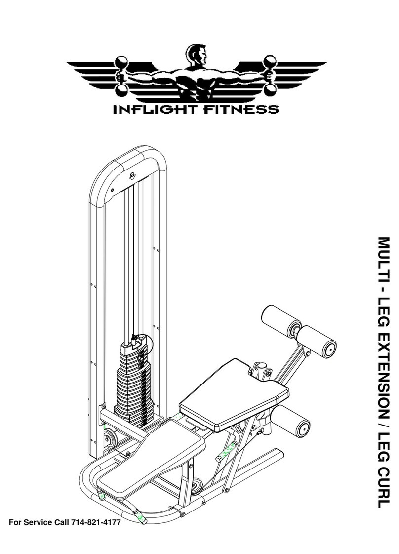
SEATED LEG EXTENSION/LEG CURL

SEATED LEG EXTENSION/LEG CURL

CT-MSEC ASSEMBLY INSTRUCTIONS
IMPORTANT NOTICES
Read all warning labels, instruction placardsand this manual before attempting
to use this machine. Always consult your physician and an exercise professional
before beginning any exercise program/regimen.
Before any test or use check for proper assembly of the machine including (but
not limited to): bolts and other hardware fastened properly, cables in pulley
grooves and routed correctly. For safety use only the top weight for the first
machine movement.
Maintain your machine in good working order by following the maintenance
schedule provided on the equipment.
It is strongly recommended that a qualified dealer assemble this
CT-MSEC Seated Leg Extension/Leg Curl machine.
Should there be any question during assembly contact your authorized Inflight Fitness
dealer or call direct to 714 821 4177.
Before beginning assembly read this instruction manual thoroughly. Unpack and verify
all parts and hardware quantities against the parts and hardware lists.
Follow the assembly steps in sequence. Failure to follow the order of assembly will
result in disassembly later and possible damage to the machine components.
The 3/8” nuts provided with this machine are “centerlocking”. They provide a more
secure assembly than nylon locking nuts. Please note they do require more force to
tighten than nylon locking nuts.
1
1

CT-MSEC PARTS AND HARDWARE
PARTS
PLATINUM FRAME PARTS
Main Upright Seat Frame Base Tube
Exercise Arm Frame Support Ass’y Handle Ass’y
Guide Rod Bracket Forward Seat Support
CUSHION FRAME PARTS
Back Support Back Pad Bottom Pad
Exercise Pad Ass’y Thigh Pad Ass’y
CABLES AND PULLEYS
Upper MSEC Cable Lower MSEC Cable 4 ½” Pulleys (8)
MISCELLANEOUS
Guide Rods (2) Lube Weight Stack Cushions (2)
Pulley Bracket Instruction Placard Triangular Plate
Weight Labels Manual Top Weight
Weight Pin with Lanyard 10 – 10# Weight Plates 10 – 5# Weight Plates
2
2

CT-MSEC PARTS AND HARDWARE
HARDWARE
DESCRIPTION QUANTITY
Bolts
1/2” x 5 ½” 1
3/8” x 4 ¾” 12
3/8” x 4” 1
3/8” x 3 ¾” 1
3/8” x 3” w/ blue patch 1
3/8” x 2 ½” 2
3/8” x 2 ½” w/ blue patch 2
3/8” x 2 ¼” 1
3/8” x 2” 4
3/8” x 2” w/ blue patch 3
3/8” x 1 ¾” 2
3/8” x 1” w/ blue patch 1
3/8” x ¾” w/ blue patch 2
3/8” x ½” w/ blue patch 1
Washers
1/2” Flat Washers 2
3/8” Flat Washers 37
3/8” Curved Washers 16
Cam Washer 1
Nuts and Miscellaneous
3/8” Nuts 23
3

CT-MSEC ASSEMBLY INSTRUCTIONS
MAIN STRUCTURE ASSEMBLY
A1. Assemble the Seat Frame to the Base Tube using 2 – 3/8” x 4 ¾” bolts, 4 – curved
washers and 2 – 3/8” nuts. Do not fully tighten the bolts at this time.
A2.Assemble the Main Upright to the assembly created in Step A1using 2 – 3/8” x 4
¾” bolts, 4–flat washers, and 2 – 3/8” nuts. Do not fully tighten the bolts at this time.
4
4

1 - Seat Frame
1 - Base Tube
2 - 3/8" x 4 3/4" Bolts
4 - Curved Washers
2 - 3/8" Nuts
A1
A2
5
1 - Main Upright
2 - 3/8" x 4 3/4' Bolts
4 - Flat Washers
2 - 3/8" Nuts
5
CT-MSEC ASSEMBLY INSTRUCTIONS
SHROUD INSTALLATION
F1. Attach five double shroud brackets to the Main Upright using the preinstalled button
head screws and washers.
F2. Attach the one single side shroud bracket to the Main Upright behind the lower
pulley using the pre-installed button head screw and washer.
F3. Attach the front shroud to the brackets using 5 – 1/4” x ¾” button head screws and
1/4”washers.
F4. Attach the rear shroud to the brackets using 6 – 1/4” x ¾” button head screws and
1/4”washers.
16

CT-MSEC ASSEMBLY INSTRUCTIONS
MAIN STRUCTURE ASSEMBLY (continued)
B1.Assemble the Exercise Arm Frame Assembly to the assembly made in Step A2
using 2 –3/8” x 4 ¾” bolts, 4 –curved washers and 2 –3/8” nuts. Do not fully tighten
the bolts at this time.
B2.Assemble the Support Assembly to the lower tube of the Exercise Arm Frame
Assembly and to the Main Upright using 4 –3/8” x 4 ¾” bolts, 8 –curved washers,
and 4 –3/8” nuts. Do not fully tighten the bolts at this time.
B3.Assemble the Support Assembly to the pivot flange of the Exercise Arm Assembly
using 2 –3/8” x 2 ½” bolts, 2 – 3/8” flat washers, and 2 – 3/8” nuts.
B4.Attach the Forward Seat Support to the Seat Frame using 2- 3/8” x ¾” bolts with
blue patch and 2 –3/8” flat washers, and to the Exercise Arm Assembly using 1 –
3/8” x ½” bolt with blue patch and 1 –3/8” washer.
FULLY TIGHTEN ALL BOLTS AT THIS TIME
B5.Attach the Handle Assembly to the Seat Frame using 2 -3/8” x 4 ¾” bolts, 4 –3/8”
washers and 2 – 3/8” nuts. Tighten these bolts.
6
6

1 - Exercise Arm Frame Assembly
2 - 3/8" x 4 3/4" Bolts
4 - Curved Washers
2 - 3/8" Nuts
1 - Support Assembly
4 - 3/8" x 4 3/4" Bolts
8 - Curved Washers
4 - 3/8" Nuts
2 - 3/8" x 2 1/2" Bolts
4 - 3/8" Flat Washers
2 - 3/8" Nuts
(Cam hidden for clarity)
1 - Handle Assembly
2 - 3/8" x 4 3/4" Bolts
4 - 3/8" Flat Washers
2 - 3/8" Nuts
1 - Forward Seat Support
1 - 3/8" x 1/2" Bolt
w/ blue patch
2 - 3/8" x 3/4" Bolt
w/ blue patch
3 - 3/8" Flat Washers
7
B1
B3
B4
B5
B2
7
CT-MSEC ASSEMBLY INSTRUCTIONS
CABLE ADJUSTMENT
F1. Adjust cable tension per the following:
1. Raise the exercise arm to the highest leg curl position.
2. Make sure bolt was installed in second weight plate (STEP D5).*
3. Use the cam washer first to remove slack from the cable.
4. Use the threaded fitting on the top weight if needed to remove more slack.
5. Cable adjustment should be tight enough to raise the pulley arm to the stop
without raising the top weight.
6. Check that the weight pin engages in each weight plate.
Note: If installing shrouds skip Step F2 and proceed to step G1.
F2. Remove backing from foam tape on Instruction Placard. Attach Instruction Placards
to Loop Upright aligning outside edge of placard to top and outside edge of Loop
Upright. Remove the protective clear cover.
14

CT-MSEC ASSEMBLY INSTRUCTIONS
PAD ASSEMBLY
C1. Assemble the Exercise Pad to the Exercise Arm using 1 – ¾” x 2 ½” Shaft, 1 –3/8”
x 3 ¾” bolt, 2 – 3/8” flat washers and 1 – 3/8” nut.
C2. Insert the 1” x 4” Shaft into the bushings of the Thigh Pad Assembly. Assemble the
Thigh Pad Assembly to the Exercise Arm Frame Assembly by first pulling the pop
pin. Then insert the guide pin into the slot and rotate the bushing and shaft down
between the plates at the top hole. Release the pop pin. Secure the Thigh Pad
Assembly using 1–1/2” x 5 ½” bolt, 2 –1/2” flat washers, and 1 – 1/2” nut.
C3. Depress the ratchet lever on the Seat Frame and insert the chrome Back Support.
Secure with a 3/8” x 1” bolt with blue patch in the threaded fitting below.
C4. Attach the Back Pad to the Back Support using 2 - 3/8” x 2 ½” bolts with blue patch
and 2 –3/8’ flat washers.
C5. Attach the Bottom Pad to the Seat Frame using 2 -3/8” x 2” bolts with blue patch, 1-
3/8” x 3” bolt with blue patch and 3 – 3/8” washers.
8
8
1 - 4 1/2" Pulley
1 - 3/8" x 2" Bolt
2 - 3/8" Flat Washers
1 - 3/8" Nut
1 - 4 1/2" Pulley
1 - 3/8" x 1 3/4" Bolt
2 - 3/8" Flat Washers
1 - 3/8" Nut
1 - 4 1/2" Pulley
1 - 3/8" x 2" Bolt
w/ blue patch
1 - 3/8" Flat Washers
1 - 4 1/2" Pulley
1 - 3/8" x 2 1/4" Bolt
2 - 3/8" Flat Washers
1 - 3/8" Nut
1 - 4 1/2" Pulley
1 - 3/8" x 1 3/4" Bolt
2 - 3/8" Flat Washers
1 - 3/8" Nut
E2
E3
E4
E5
E6
B
1 - Lower Cable
1 - 4 1/2" Pulley
1 - Pulley Bracket
1 - 3/8" x 2" Bolt
2 - 3/8" Flat Washers
1 - 3/8" Nut
Cable end in hook
13
E7
E1

Back Support
1 - 3/8" x 1" Bolt
w/ blue patch
(Depress ratchet lever to install)
1 - Back Pad
2 - 3/8" x 2 1/2" Bolts
w/ blue patch
2 - 3/8" Flat Washers
1 - Bottom Pad
1 - 3/8" x 3" Bolt
w/ blue patch
2 - 3/8" x 2" Bolt
w/ blue patch
3 - 3/8" Flat Washers
C1
C2
C3
C5
C4
1 - Exercise Pad
1 - 3/4" x 2 1/2" Shaft
1 - 3/8" x 3 3/4" Bolt
2 - 3/8" Flat Washers
1 - 3/8" Nut
1 - Thigh Pad Ass'y
1 - 1" x 4" Shaft
1 - 1/2" x 5 1/2" Bolt
2 - 1/2" Washers
1 - 1/2" Nut
(Pull pop pin to install)
9
9
CT-MSEC ASSEMBLY INSTRUCTIONS
WEIGHT STACK AND CABLE ASSEMBLY
E1. Attach a ball end of the MSEC Lower Cable to the “U”-Bracket. Place a 4 ½” pulley
onto the MSEC Upper Cable below the Triangular Bracket and fasten using the “U”-
Bracket, 1 –3/8” x 2” bolt, 2 –3/8” flat washers, and 1 –3/8” nut.
E2. Route the cable down between the plates welded to the base of the Loop Upright.
Install a 4 ½” pulley over the cable and attach to the plates using 1 –3/8” x 2” bolt, 2
–3/8” flat washers, and 1 –3/8” nut.
E3. Route the cable around a 4 ½” pulley and place the pulley into the pulley bracket
welded on the base of the Exercise Arm Assembly. Fasten the pulley using 1 –3/8”
x 2” bolt with blue patch and 1 –3/8” flat washer.
E4. Route the cable under a 4 ½”pulley and place in the pulley bracket welded at the
base of the Support Assembly. Attach the pulley using 1 – 3/8” x 1 ¾” bolt, 2 –3/8”
flat washers, and 1 –3/8” nut.
E5. Route the cable up to and through the pulley bracket welded at the top of the
Support Assembly. Place a 4 ½” pulley under the cable inside the pulley bracket
and fasten using 1 – 3/8” x 1 ¾” bolt, 2 –3/8” flat washers, and 1 –3/8” nut.
E6. Route the cable under a 4 ½” pulley and place inside the pulley arm of the Exercise
Arm Frame and fasten using 1 –3/8” x 2 ¼” bolt, 2 –3/8” flat washers, and 1 –3/8”
nut.
E7.Route the cable up to and inside the cam. Insert the ball end into the hook welded
inside the cam.
12

CT-MSEC ASSEMBLY INSTRUCTIONS
WEIGHT STACK AND CABLE ASSEMBLY
D1. Insert Guide Rods into the base of the Loop Upright. Allow Guide Rods to lean back
away from the machine. Place one weight stack cushion on each Guide Rod and
slide down to the base. Apply lubricant to the Guide Rods from the weight stack
cushions to the tops of the Guide Rods.
Making sure that the recess for the weight labels is facing towards the machine and
that the three pads are facing down slide onto the Guide Rods: 10 – 10lb. weight
plates and 10 –5lb weight plates. Place the Top Weight with Cable on the Guide
Rods with the drilled hole facing the machine and slide down to the stack.
D2. Before proceeding with the cable installation slide the loop of the weight pin lanyard
over the end of the Upper MSEC Cable down to the top weight.
D3. Install Guide Rod Bracket onto top of guide rods. Place the Upper MSEC Cable
over one 4 ½” pulley and slide up between the plates of the Loop Upright at the slot.
Stand the weight stack assembly upright and bolt the Guide Rod Bracket, Pulley and
Loop Upright together using 1 –3/8” x 2” bolt, 1 -Cam Washer, 2 –3/8” flat
washers, and 1 –3/8” nut. Do not tighten at this time.
D4. Place a pulley under the cable and insert between the plates of the Loop Upright.
Fasten the pulley and the triangular plate using 1 –3/8” x 2” bolt, 2 –3/8” flat
washers, and 1 –3/8” nut. Use the pre-installed pin and E-clip to attach the end of
the cable to the hole in the triangular plate.
D5. Bolt the second 5lb. weight to the selector stem using 1 -3/8” x 4” bolt and 1 –3/8”
nut.NOTE: If a heavy stack is being installed bolt the first weight plate to the
selector stem using the bolt provided with the heavy stack.
10
10
2 - Weight Stack Cushions
2 - Guide Rods
10 - 10lb. Weight Plates
10 - 5lb. Weight Plates
1 - Top Weight w/ cable
1 - 4 1/2" Pulley
1 - Guide Rod Bracket
1 - 3/8" x 2" Bolt
1 - Cam Washer
2 - 3/8" Flat Washers
1 - 3/8" Nut
1 - Upper Cable
1 - Weight Pin
w/Lanyard
1 - 4 1/2" Pulley
1 - Triangular Plate
1 - 3/8" x 2" Bolt
2 - 3/8" Flat Washers
1 - 3/8" Nut
1 - Pin and clip (in cable)
1 - 3/8" x 4" Bolt
1 - 3/8" Nut
11
D3
D5
D4
D2
D1

CT-MSEC ASSEMBLY INSTRUCTIONS
WEIGHT STACK AND CABLE ASSEMBLY
D1. Insert Guide Rods into the base of the Loop Upright. Allow Guide Rods to lean back
away from the machine. Place one weight stack cushion on each Guide Rod and
slide down to the base. Apply lubricant to the Guide Rods from the weight stack
cushions to the tops of the Guide Rods.
Making sure that the recess for the weight labels is facing towards the machine and
that the three pads are facing down slide onto the Guide Rods: 10 – 10lb. weight
plates and 10 –5lb weight plates. Place the Top Weight with Cable on the Guide
Rods with the drilled hole facing the machine and slide down to the stack.
D2. Before proceeding with the cable installation slide the loop of the weight pin lanyard
over the end of the Upper MSEC Cable down to the top weight.
D3. Install Guide Rod Bracket onto top of guide rods. Place the Upper MSEC Cable
over one 4 ½” pulley and slide up between the plates of the Loop Upright at the slot.
Stand the weight stack assembly upright and bolt the Guide Rod Bracket, Pulley and
Loop Upright together using 1 –3/8” x 2” bolt, 1 -Cam Washer, 2 –3/8” flat
washers, and 1 –3/8” nut. Do not tighten at this time.
D4. Place a pulley under the cable and insert between the plates of the Loop Upright.
Fasten the pulley and the triangular plate using 1 –3/8” x 2” bolt, 2 –3/8” flat
washers, and 1 –3/8” nut. Use the pre-installed pin and E-clip to attach the end of
the cable to the hole in the triangular plate.
D5. Bolt the second 5lb. weight to the selector stem using 1 -3/8” x 4” bolt and 1 –3/8”
nut.NOTE: If a heavy stack is being installed bolt the first weight plate to the
selector stem using the bolt provided with the heavy stack.
10
2 - Weight Stack Cushions
2 - Guide Rods
10 - 10lb. Weight Plates
10 - 5lb. Weight Plates
1 - Top Weight w/ cable
1 - 4 1/2" Pulley
1 - Guide Rod Bracket
1 - 3/8" x 2" Bolt
1 - Cam Washer
2 - 3/8" Flat Washers
1 - 3/8" Nut
1 - Upper Cable
1 - Weight Pin
w/Lanyard
1 - 4 1/2" Pulley
1 - Triangular Plate
1 - 3/8" x 2" Bolt
2 - 3/8" Flat Washers
1 - 3/8" Nut
1 - Pin and clip (in cable)
1 - 3/8" x 4" Bolt
1 - 3/8" Nut
11
D3
D5
D4
D2
D1
11

CT-MSEC ASSEMBLY INSTRUCTIONS
WEIGHT STACK AND CABLE ASSEMBLY
E1. Attach a ball end of the MSEC Lower Cable to the “U”-Bracket. Place a 4 ½” pulley
onto the MSEC Upper Cable below the Triangular Bracket and fasten using the “U”-
Bracket, 1 –3/8” x 2” bolt, 2 –3/8” flat washers, and 1 – 3/8” nut.
E2. Route the cable down between the plates welded to the base of the Loop Upright.
Install a 4 ½” pulley over the cable and attach to the plates using 1 – 3/8” x 2” bolt, 2
–3/8” flat washers, and 1 – 3/8” nut.
E3. Route the cable around a 4 ½” pulley and place the pulley into the pulley bracket
welded on the base of the Exercise Arm Assembly. Fasten the pulley using 1 –3/8”
x 2” bolt with blue patch and 1 – 3/8” flat washer.
E4. Route the cable under a 4 ½”pulley and place in the pulley bracket welded at the
base of the Support Assembly. Attach the pulley using 1 –3/8” x 1 ¾” bolt, 2 – 3/8”
flat washers, and 1 –3/8” nut.
E5. Route the cable up to and through the pulley bracket welded at the top of the
Support Assembly. Place a 4 ½” pulley under the cable inside the pulley bracket
and fasten using 1 –3/8” x 1 ¾” bolt, 1 –3/8” flat washers, 1 3/8”small washer (on
weld side) and 1 –3/8” nut.
E6. Route the cable under a 4 ½” pulley and place inside the pulley arm of the Exercise
Arm Frame and fasten using 1 –3/8” x 2 ¼” bolt, 2 – 3/8” flat washers, and 1 – 3/8”
nut.
E7. Route the cable up to and inside the cam. Insert the ball end into the hook welded
inside the cam.
12

1 - 4 1/2" Pulley
1 - 3/8" x 2" Bolt
2 - 3/8" Flat Washers
1 - 3/8" Nut
1 - 4 1/2" Pulley
1 - 3/8" x 1 3/4" Bolt
2 - 3/8" Flat Washers
1 - 3/8" Nut
1 - 4 1/2" Pulley
1 - 3/8" x 2" Bolt
w/ blue patch
1 - 3/8" Flat Washers
1 - 4 1/2" Pulley
1 - 3/8" x 2 1/4" Bolt
2 - 3/8" Flat Washers
1 - 3/8" Nut
1 - 4 1/2" Pulley
1 - 3/8" x 1 3/4" Bolt
1 - 3/8" Flat Washer
1 - 3/8" Small Flat Washer
(on weld side)
1 - 3/8" Nut
E2
E3
E4
E5
E6
B
1 - Lower Cable
1 - 4 1/2" Pulley
1 - Pulley Bracket
1 - 3/8" x 2" Bolt
2 - 3/8" Flat Washers
1 - 3/8" Nut
Cable end in hook
13
E7
E1

CT-MSEC ASSEMBLY INSTRUCTIONS
CABLE ADJUSTMENT
F1. Adjust cable tension per the following:
1. Raise the exercise arm to the highest leg curl position.
2. Make sure bolt was installed in second weight plate (STEP D5).*
3. Use the cam washer first to remove slack from the cable.
4. Use the threaded fitting on the top weight if needed to remove more slack.
5. Cable adjustment should be tight enough to raise the pulley arm to the stop
without raising the top weight.
6. Check that the weight pin engages in each weight plate.
Note: If installing shrouds skip Step F2 and proceed to step G1.
F2. Remove backing from foam tape on Instruction Placard. Attach Instruction Placards
to Loop Upright aligning outside edge of placard to top and outside edge of Loop
Upright. Remove the protective clear cover.
14
14

CT-MSEC ASSEMBLY INSTRUCTIONS
MAIN STRUCTURE ASSEMBLY (continued)
B1.Assemble the Exercise Arm Frame Assembly to the assembly made in Step A2
using 2 –3/8” x 4 ¾” bolts, 4 –curved washers and 2 –3/8” nuts. Do not fully tighten
the bolts at this time.
B2.Assemble the Support Assembly to the lower tube of the Exercise Arm Frame
Assembly and to the Main Upright using 4 –3/8” x 4 ¾” bolts, 8 –curved washers,
and 4 –3/8” nuts. Do not fully tighten the bolts at this time.
B3.Assemble the Support Assembly to the pivot flange of the Exercise Arm Assembly
using 2 –3/8” x 2 ½” bolts, 2 – 3/8” flat washers, and 2 – 3/8” nuts.
B4.Attach the Forward Seat Support to the Seat Frame using 2- 3/8” x ¾” bolts with
blue patch and 2 –3/8” flat washers, and to the Exercise Arm Assembly using 1 –
3/8” x ½” bolt with blue patch and 1 –3/8” washer.
FULLY TIGHTEN ALL BOLTS AT THIS TIME
B5.Attach the Handle Assembly to the Seat Frame using 2 -3/8” x 4 ¾” bolts, 4 –3/8”
washers and 2 – 3/8” nuts. Tighten these bolts.
6
1- Placard
Only install if not installing shrouds
Remove protective film after installation
20 - Weight Labels
1.
5.
F2
Cable Adjustment
15
1. Make sure bolt was installed in
second weight plate (STEP D5).*
2. Raise the exercise arm to the
highest leg curl position.
3. Use the cam washer first to
remove slack from the cable.
4. Use the threaded fitting on the top
weight if needed to remove more slack.
5. Cable adjustment should be tight
enough to raise the pulley arm to the stop
without raising the top weight.
6. Check that the weight pin
pins in each weight plate.
2.
3. 4.
Maximum 1" from
under bolt head to
bottom of jam nut
*First weight plate if installing a heavy stack
F1
F2
15

1 - Seat Frame
1 - Base Tube
2 - 3/8" x 4 3/4" Bolts
4 - Curved Washers
2 - 3/8" Nuts
A1
A2
5
1 - Main Upright
2 - 3/8" x 4 3/4' Bolts
4 - Flat Washers
2 - 3/8" Nuts
CT-MSEC ASSEMBLY INSTRUCTIONS
SHROUD INSTALLATION
F1. Attach five double shroud brackets to the Main Upright using the preinstalled button
head screws and washers.
F2. Attach the one single side shroud bracket to the Main Upright behind the lower
pulley using the pre-installed button head screw and washer.
F3. Attach the front shroud to the brackets using 5 – 1/4” x ¾” button head screws and
1/4”washers.
F4. Attach the rear shroud to the brackets using 6 – 1/4” x ¾” button head screws and
1/4”washers.
16
16

CT-MSEC ASSEMBLY INSTRUCTIONS
MAIN STRUCTURE ASSEMBLY
A1. Assemble the Seat Frame to the Base Tube using 2 – 3/8” x 4 ¾” bolts, 4 – curved
washers and 2 – 3/8” nuts. Do not fully tighten the bolts at this time.
A2.Assemble the Main Upright to the assembly created in Step A1using 2 – 3/8” x 4
¾” bolts, 4–flat washers, and 2 – 3/8” nuts. Do not fully tighten the bolts at this time.
4
5 - Double Shroud Brackets
1 - Single Shroud Bracket
1 - Rear Shroud
6 - 1/4" Screws
6 - 1/4" Washers
1 - Front Shroud
5 - 1/4" Screws
5 - 1/4" Washers
F1
F2
17
F4
F3
17

Table of contents
Other Inflight Fitness Fitness Equipment manuals

Inflight Fitness
Inflight Fitness CT-ILPC User manual

Inflight Fitness
Inflight Fitness CT-MHP User manual

Inflight Fitness
Inflight Fitness Mab User manual

Inflight Fitness
Inflight Fitness MULTI-FLY/DELT User manual

Inflight Fitness
Inflight Fitness VANGUARD User manual
Inflight Fitness
Inflight Fitness VANGUARD User manual
Inflight Fitness
Inflight Fitness Multi-Lat/Arm User manual

Inflight Fitness
Inflight Fitness SMITH MACHINE User manual
Inflight Fitness
Inflight Fitness MEC User manual

Inflight Fitness
Inflight Fitness Liberator User manual