manuals.online logo
Brands
  1. Home
  2. •
  3. Brands
  4. •
  5. Inflight Fitness
  6. •
  7. Fitness Equipment
  8. •
  9. Inflight Fitness VANGUARD User manual

Inflight Fitness VANGUARD User manual

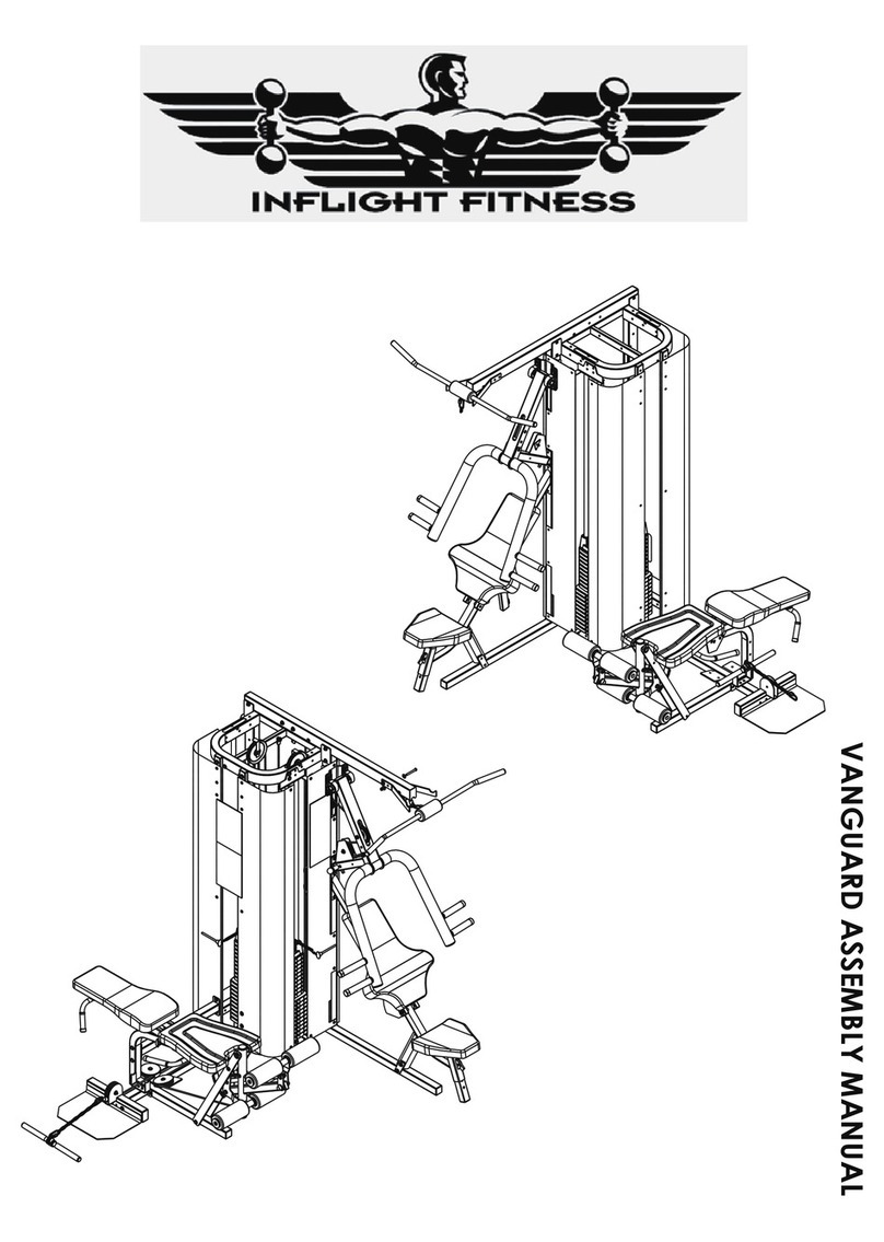
VANGUARD with LEG PRESS OPTION
ASSEMBLY MANUAL
VANGUARD with LEG PRESS OPTION
ASSEMBLY MANUAL
1
VANGUARD/LPO ASSEMBLY INSTRUCTIONS
IMPORTANT NOTICES
IF YOU ARE ASSEMBLING THIS VANGUARD FITNESS MACHINE WITH THE
CABLE COLUMN OPTION YOU WILL NEED TO USE THIS ASSEMBLY MANUAL
AND THE ASSEMBLY MANUAL INCLUDED WITH THE CLM OPTION.
Read all warning labels, instruction placardsand this manual before attempting
to use this machine. Always consult your physician and an exercise professional
before beginning any exercise program/regimen.
Before any test or use check for proper assembly of the machine including (but
not limited to): bolts and other hardware fastened properly, cables in pulley
grooves and routed correctly. For safety use only the top weight for the first
machine movement.
Maintain your machine in good working order by following the maintenance
schedule provided on the equipment.
It is strongly recommended that a qualified dealer assemble this
Vanguard exercise machine.
Should there be any question during assembly contact your authorized Inflight Fitness
dealer or call direct to 714 821 4177.
Before beginning assembly read this instruction manual thoroughly. Unpack and verify
all parts and hardware quantities against the parts and hardware lists. Please note that
there is an additional cable packed (P13-0452) that is not required when building a
Vanguard with an LPO.
Follow the assembly steps in sequence. Failure to follow the order of assembly will
result in disassembly later and possible damage to the machine components.
The 3/8” nuts provided with this machine are “centerlocking”. They provide a more
secure assembly than nylon locking nuts. Please note they do require more force to
tighten than nylon locking nuts.
1
2 3
VANGUARD/LPO PARTS AND HARDWARE
PARTS
PLATINUM FRAME PARTS
Main Upright Base Tube Mid-Frame
Base Frame MEC Lower Attach Top Beam
Top Frame Vertical Tubes (2) Low Row Tube
Low Row Connector Main MEC Frame Round Cable Retainer (2)
“L” Pulley Plate Notched G.R. Bracket Angled G.R. Bracket
Seat Frame Press Arm Angle Cable Retainer (2)
L/H Bracket R/H Bracket Bearing Brackets (2)
Press Arm Support Flat Pulley Plates (2) Bent Pulley Plate (1-hole)
MEC Exercise Arm Double Pulley Bracket Bent Pulley Plate (2-hole)
MEC Support Tube LPO Seat Frame LPO Connector Tube
Leg Press Arm Threaded Yoke
BLACK FRAME PARTS
Foot Plate MEC Seat Plate MEC Back Support Tube w/ Plate
Leg Curl Handle Seat Handles (2) MEC Back Support Tube (21”)
Long Back Support (23”) Short Back Support L/H Lat Bar Holder
R/H Lat Bar Holder Lat Bar Bar Rest
LPO Footplate LPO Handle
2
VANGUARD/LPO PARTS AND HARDWARE
HARDWARE
DESCRIPTION
Vanguard Hardware Pack (3)
Vanguard LPO Hardware Pack
NOTE: USE THE BOLTS WITH BLUE PATCH WHERE INDICATED BY THIS MANUAL
CABLES AND PULLEYS
P13-0453 Cable P13-0454 Cable P13-0455 Cable
P13-0458 Cable P13-0459 Cable 4 ½” Pulleys (18)
6” Pulleys (3) (Additional P14-0452 cable is not needed with LPO)
PADS
MEC Seat Pad Back Pad Rollers (4)
Back/Thigh Pad Six-sided Pad 9” x 16” Pad (2)
MISCELLANEOUS
Guide Rods (4) Lube (2) Weight Stack Cushions (4)
Low Row/Bicep Bar Seat Stem Chrome Retainer Plates (4)
LPO Back Tube 3/4” x 3” Shaft Top Weights (2)
Quick Links (2) Instruction Placards (4) Weight Pins w/Lanyard (2)
20 –10# Weight Plates 20 –5# Weight Plates Pillow Block Bearings (4)
Roller Tubes (4) Weight Labels Touch Up Paint
3
4 5
VANGUARD/LPO ASSEMBLY INSTRUCTIONS
MAIN STRUCTURE ASSEMBLY
A1. Assemble the Base Frame to the Main Upright and Base tube using 1–3/8” x 3”
bolts, 2 – 3/8” x 2 ¾” bolts, 6 – 3/8” flat washers and 3 – 3/8” nuts. Do not fully
tighten the bolts at this time.
A2.Assemble the Mid-Frame and LPO Connector to the assembly created in Step A1.
using 2 – 3/8” x 3½” bolts, 1 – 3/8” x 3 ¼” bolts, 4 – 3/8” flat washers, and 2 – 3/8”
nuts. Do not fully tighten the bolts at this time.
A3.Assemble the MEC Lower Attach to the assembly created in Step A2.using 2 – 3/8”
x3” bolts, 4 – 3/8” washers, and 2 – 3/8” nuts. Do not fully tighten the bolts at this
time.
A4. Attach the One Hole Bent Pulley Bracket and the Two Hole Bent Pulley Bracket to
the MEC Lower Attach using 2 –3/8” x 3” bolts, 4 –3/8” washers and 2 –3/8” nuts.
A5. Attach the Leg Press Option (LPO) Seat Frame to the LPO Connector using 2 –
3/8” x 2 ¾” bolts, 4 –3/8” washers and 2 –3/8” nuts.
4
Base Frame
Main Upright
Base Tube
2 - 3/8" x 2 3/4" Bolts
1 - 3/8" x 3" Bolts
6 - Washers
3 - Nuts
Mid-Frame
LPO Connector*
2 - 3/8" x 3 1/2" Bolts*
1 - 3/8" x 3 1/4" Bolt
6 - Washers
3 - Nuts
1 - Bent Pulley Bracket
(1-hole)
1 - Bent Pulley Bracket
(2-hole)
2 - 3/8" x 3" Bolts
4 - Washers
2 - Nuts
MEC Lower Attach
2 - 3/8" x 3" Bolts
4 - Washers
2 - Nuts
A1
A2
A3
A4
NOTE: DO NOT FULLY TIGHTEN BOLTS UNTIL AFTER
STEP B3.
LPO Seat Frame*
2 - 3/8" x 2 3/4" Bolts*
4 - Washers*
2 - Nuts*
A5
* ITEMS IN LPO BOX
5
6 7
VANGUARD/LPO ASSEMBLY INSTRUCTIONS
MAIN STRUCTURE ASSEMBLY
B1.Assemble the Top Frame to the Main Upright using 2 –3/8” x 3” bolts, 4 –3/8” flat
washers and 2 –3/8” nuts. Do not fully tighten the bolts at this time.
B2.Assemble the Vertical Tubes to the Lower Frame and Top Frame using 4 –3/8” x 3
½” bolts, 8 –3/8” flat washers, and 4 –3/8” nuts. Do not fully tighten the bolts at this
time.
B3.Assemble the Top Beam to the Main Upright and Top Frame using 1 –3/8” x 3”
bolts, 2 –3/8” x 2 ¾” bolts, 6 –3/8” washers, and 3 –3/8” nuts.
FULLY TIGHTEN ALL BOLTS AT THIS TIME
B4.Attach the “L” Pulley Plate to the Lower Frame using 2- 3/8” x 2¾” bolts, 4 –3/8”
flat washers, and 2 – 3/8” nuts. Tighten these bolts.
B5.Attach the Main MEC Frame and Low Row Connector to the MEC Lower Attach
using 2 -3/8” x 3” bolts, 4 –3/8” washers and 2 – 3/8” nuts.Do NOT fully tighten
these bolts until after Step K2.
B6.Attach the Footplate and Low Row Tube to the Low Row Connector using 2 -3/8” x
3” bolts, 4 – 3/8” washers and 2 –3/8” nuts. Tighten these bolts.
6
2 - Vertical Tubes
4 - 3/8" x 3 1/2" Bolts
8 - Washers
4 - Nuts
Top Beam
1 - 3/8" x 3" Bolt
2 - 3/8" x 2 3/4" Bolt
6 - Washers
3 - Nuts
1 - "L" Pulley Plate
2 - 3/8" x 2 3/4" Bolts
4 - Washers
2 - Nuts
1 - Footplate
1 - Low Row Tube
2 - 3/8" x 3" Bolts
4 - Washers
2 - Nuts
1 - Main MEC Frame
1 - Low Row Connector
2 - 3/8" x 3" Bolts
4 - Washers
2 - Nuts
DO NOT FULLY TIGHTEN
NOTES:
Fully tighten all bolts except
Step B5
.
At this time check the position of the
frame in the room. Center the footplate
over the LPO seat frame if necessary.
After the weight stacks are installed
the machine will be too heavy to move.
B1
B3
B2
B4
B5
B6
7
WARNING:
Do
not
put a bolt into this hole
Top Frame
2 - 3/8" x 3" Bolts
4 - Washers
2 - Nuts
8 9
VANGUARD/LPO ASSEMBLY INSTRUCTIONS
WEIGHT STACK INSTALLATION
C1. Insert 2 - Guide Rods into the two large holes in the Mid Frame near the center of
the machine. Allow Guide Rods to lean together out the side of the machine. Place
one weight stack cushion on each Guide Rod and slide down to the base. Apply
lubricant to the Guide Rods from the weight stack cushions to the tops of the Guide
Rods.
Making sure that the recess for the weight labels is facing out from the frame and
that the three pads are facing down slide onto the Guide Rods: 10 –10lb. weights
and then 10 –5lb. weights. Place a Top Weight on the Guide Rods with the drilled
hole facing out from the machine and slide down to the stack. Slide the loop of the
weight pin lanyard over the threaded boss in the center of the top weight.
Insert the pins of the Notched Guide Rod Bracket into the rubber cushions on top of
guide rods. Give the guide rods a little shake to help align the weight plates. Bolt
the Notched Guide Rod Bracket to the Top Frame using 2 –3/8” x 2 ¾” bolts, 4 –
3/8” washers and 2 –3/8” nuts.
C2. Insert 2 -Guide Rods into the two large holes in the Base Frame near the side of
the machine where you will assemble the multi-press. Allow Guide Rods to lean
together away from the machine. Place one weight stack cushion on each Guide
Rod and slide down to the base. Apply lubricant to the Guide Rods from the weight
stack cushions to the tops of the Guide Rods.
Install the weight plates as in Step C1.
Install the Angled Guide Rod Bracket onto top of guide rods to the Top Frame (with
the Upper Shroud Bracket from the shroud box if shrouds will be installed later)
using 2 –3/8” x 2 ¾” bolts, 4 –3/8” washers and 2 –3/8” nuts.
C3. If shrouds will be installed, bolt the Lower Shroud Bracket from the shroud box to
the Base Frame using 2 – 3/8” x 2 ¾” bolts, 4 –3/8” washers, and 2 –3/8” nuts
8
2 - Guide Rods
2 - Weight Cushions
10 - 10lb. Weight Plates
10 - 5lb. Weight Plates
1 - Top Weight
1 - Notched G.R. Bracket
2 - 3/8" x 2 3/4" Bolts
4 - Washers
2 - Nuts
2 - Guide Rods
2 - Weight Cushions
10 - 10lb. Weight Plates
10 - 5lb. Weight Plates
1 - Top Weight
1 - Angled G. R. Bracket
1 - Upper Shroud Bracket*
2 - 3/8" x 2 3/4" Bolts
4 - Washers
2 - Nuts
Lower Shroud Bracket*
2 - 3/8" x 2 3/4" Bolts*
4 - Washers*
2 - Nuts*
9
C1
C2
C3*
Top Frame hidden for clarity
NOTE:
Steps and parts marked with* are
only if shrouds are to be installed -
parts are in shroud box.
10 11
VANGUARD/LPO ASSEMBLY INSTRUCTIONS
LPO STRUCTURE ASSEMBLY
D1.Attach the Leg Press Arm to the LPO Seat Frame using 2 –1” Pillow Block
bearings, 4 -3/8” x 1 ¼” bolts, 8 -3/8” flat washers and 4–3/8” nuts. The setscrews
are oriented to the outside. Make sure the Leg Press Arm moves in line with the
LPO Seat Frame before tightening the nuts and the bearing setscrews.
D2.Attach the LPO Footplate to the Leg Press Arm using 1 – 1/2” x 4¼” bolts, 2 – 1/2”
flat washers and 1–1/2” nut.
D3.Assemble the LPO Handle to the LPO Seat Frame using 2 – 3/8” x 2 ¾” bolts, 4 –
3/8” washers, and 2 – 3/8” nuts.
D4.Insert the LPO Back Tube into the LPO Seat Frame and install 1-1/4” x ¾” cap
screw.
10
1 - Leg Press Arm
2 - 1" Pillow Block
Bearings
4 - 3/8" x 1 1/4" Bolts
8 - Washers
4 - Nuts
1 - LPO Footplate
1 - 1/2" x 4 1/4" Bolt
2 - 1/2" Washers
1 - 1/2" Nut
1 - LPO Back Tube
1 - 1/4" x 3/4" Cap Screw
1 - LPO Handle
2 - 3/8" x 2 3/4" Bolts
4 - Washers
2 - Nuts
D1*
D2*
D3*
D4*
11
* ITEMS IN LPO BOX
12 13
VANGUARD/LPO ASSEMBLY INSTRUCTIONS
MEC STATION STRUCTURE ASSEMBLY
E1. Attach the two Bearing Flats to the Main MEC Frame using 2 –3/8” x 4 ½” bolts, 4 –
½” barrel spacers, 4 -3/8” flat washers and 2 –3/8” nuts.
E2. Attach the MEC Exercise Arm to the Bearing Flats using 1 –3/4” x 4” Shaft, 2 – 3/8”
x 1” button head screws and 2 –3/8” small flat washers.
E3. Assemble the two Seat Handles to the Main MEC Frame using 2 – 3/8” x 3”bolts, 4
–3/8” washers, and 2 – 3/8” nuts.
E4. Assemble the MEC Back Supports to the MEC Frame using 1 –1/2” x 5 ¼” bolt, 2 –
1/2” washers and 1 –1/2” nut.
E5. Attach the Seat Plate to the MEC Frame using 1 –1/2” x 7” bolt, 2 –1/2” washers
and 1 –1/2” nut.
12
2 - Seat Handles
2 - 3/8" x 3" Bolts
4 - Washers
2 - Nuts
1 - MEC Back Support
w/ Plate (21")
1 - Back Support (21")
1 - 1/2" x 5 1/4" Bolt
2 - 1/2" Washers
1 - 1/2" Nut
1 - MEC Seat Plate
1 - 1/2" x 7" Bolt
2 - 1/2" Washers
1 - 1/2" Nut
1 - MEC Exercise Arm
1 - 3/4" x 4" Shaft
2 - 3/8" x 1" Screws
2 - Small Washers
E4
E3
E5
E2
2 - Bearing Flats
4 - 1/2" Barrel Spacers
2 - 3/8" x 4 1/2" Bolts
4 - Washers
2 - Nuts
E1
13
14 15
VANGUARD/LPO ASSEMBLY INSTRUCTIONS
MPS/MLA STATION STRUCTURE ASSEMBLY
F1. Attach the Seat Frame to the Main Upright using 2-3/8” x 3 ¾” bolts, 4 –3/8”
washers, and 2 –3/8” nuts.
F2. Attach the Seat Frame to the Base Tube using 1 L/H Bracket, 1 –R/H Bracket, 2 –
3/8” x 3” bolts, 4 –3/8” washers and 2 –3/8” nuts.
F3. Insert the Seat Stem into the Seat Frame with the positioning holes facing forward.
Install the 1/4” x ¾” socket head cap screw into the hole at the back of the Seat
Stem.
F4. Assemble the Press Arm Support Ass’y to the Main Upright using 1 –3/8” x 3 ½”
bolt with the blue patch, 1 – 3/8” x 3 ¾” bolt, 3 –3/8” washers, and 1 – 3/8” nut.
F5. Attach the two Bearing Brackets to the Main Upright using 2 –3/8” x 3” bolts, 4 –
3/8” flat washers and 2 –3/8” nuts.
F6. The Press Arm and Pillow Block Bearings attach to the Bearing Brackets using 4 –
3/8” x 1 ¼” bolts, 8 –3/8” washers, and 4 –3/8” nuts. Note: The pillow Block
Bearings install with the setscrews to the outside. The Press Arm installs with the
long slot towards the frame. Square and center the Press Arm before tightening the
bolts.
F7. Attach the Back Supports to the Seat Frame using 1 –1/2” x 5 ¼” bolt, 2 –1/2”
washers and 1 –1/2” nut.
14
1 - Seat Frame
2 - 3/8" x 3 3/4" Bolts
4 -Washers
2 - Nuts
1 - L/H Bracket
1 - R/H Bracket
2 - 3/8" x 3" Bolts
4 - Washers
2 - Nuts
1 - Seat Stem
1 - 1/4" x 3/4" Socket
Head Cap Screw
1 - Press Arm Support
1 - 3/8" x 3 3/4" Bolt
1 - 3/8" x 3 1/2" Bolt
with Blue Patch
3 - Washers
1 - Nuts
1 - Press Arm
2 - Pillow Block Bearings
4 - 3/8" x 1 1/4" Bolts
8 - Washers
4 - Nuts
2 - Bearing Brackets
2 - 3/8" x 3" Bolts
4 - Washers
2 - Nuts
F5
F6
F2
F4
F1
F3
15
1 - Short Back Tube
1 - Long Back Tube
1 - 1/2" 5 1/4" Bolt
2 - 1/2" Washers
1 - 1/2" Nut
F7
16 17
VANGUARD/LPO ASSEMBLY INSTRUCTIONS
MPS/MLA/LPO STATION CABLE ASSEMBLY
G1.Install the P13-0453 Cable starting from the slot at the end of the Top Beam. Slide
the end of the cable without the large diameter ball into the Top Beam into the Top
Beam and out down through the slots in the Top Beam and Top Frame. Install a 4
1/2” pulley underthe cable into the slot at the end of the Top Beam and bolt in place
using 1 –3/8” x 2 ½” bolt, 2 –½” step spacers and 1 -3/8” nut.
G2.Install a 4 ½” pulley under the cable up into the slots where the other end of the
cable exits the frame. Bolt the pulley in place using 1 -3/8” x 2 ¾” bolt, 1 –½” step
spacer (interior side), 1 –¾” step spacer (exterior side), and1–3/8” nut.
G3.Route the cable over a 4 ½” pulley and through the slot in the frame behind the
Press Arm. Attach the pulley using 1 -/8” x 2 ½” bolt, 2 –½” step spacers, and 1 –
3/8” nut.
G4.Route the cable around a 4 ½” pulley and install into the Press Arm using 1 –3/8” x
3 ½” bolt, 2 –1” step spacers and 1 3/8” nut.
G5.Route the cable around a 4 ½” pulley and install into the Press Arm Support using 1
–3/8” x 2” bolt, 1 –Cam washer, 2 –3/8” washers and 1 –3/8” nut. Place the Cam
washer so that the bolt is as close as possible to the triangle cam rest. Do not
tighten this bolt until it is time to adjust the cable tension.
G6.Attach the end of the cable inside the Press Arm using 1 –3/8” x 4” bolt, 2 –1 ¼”
step spacers and 1 –3/8” nut.
16
1 - P13-0453 Cable
1 - 4 1/2" Pulley
1 - 3/8" x 2 1/2" Bolt
2 - 1/2" Step Spacers
1 - Nut
1 - 4 1/2" Pulley
1 - 1/2" Step Spacer
1 - 3/4" Step Spacer
1 - 3/8" x 2 3/4" Bolt
1 - Nut
1 - 4 1/2" Pulley
2 - 1/2" Spacers
1 - 3/8" x 2 1/2" Bolt
1 - Nut
G1
G2
G3
G4
G5
G6
17
1 - 3/8" x 4" Bolt
2 - 1 1/4" Step Spacers
1 - Nut
(Cable End)
1 - 4 1/2" Pulley
1 - 3/8" x 2" Bolt
1 - Cam Washer
2 - Washers
1 - Nut
1 - 4 1/2" Pulley
2 - 1" Step Spacers
1 - 3/8" x 3 1/2" Bolt
1 - Nut
18 19
VANGUARD/LPO ASSEMBLY INSTRUCTIONS
MPS/MLA/LPO STATION CABLE ASSEMBLY (continued)
G7.Thread the P13-0458cable into the threaded boss in the Top Weight. Remember
to slide the loop of the weight pin lanyard onto the cable/topweight if you have not
done so already.
Note: There is a maximum 1” allowable from under the head of the threaded cable
end to the top of the threaded boss where the jam nut rests.
G8.Route the other end of the cable up through the guide rod bracket, through the slot
in the top frame, around a 6” pulley and back down through the slot. Attach the
pulley within the top frame using 1 – 3/8” x 2 ¾” bolt, 2 –½” step spacers, 1 –Angle
Cable Retainer, 1 –3/8” washer and 1 –3/8” nut.
G9.Route the cable end around a 6” pulley and attach the pulley to the “L” pulley
bracket using 1 –3/8” x 1 ¾” bolt, 2 –3/8” washers, and 1 –3/8” nut.
G10.Assemble one 4 ½” pulley between the two Flat Pulley Plates using 1 –3/8” x 1 ¾”
bolt, 2 –3/8” washers and 1 –3/8” nut. Place this assembly over the upper cable
installed in Steps G1-6. Route the lower cable over a 4 ½” pulley and bolt it between
the pulley plates using 1 –3/8” x 1 ¾” bolt, 2 –3/8” washers and 1 –3/8” nut.
G11.Attach the end of the cable to the Top Frame using 1 –3/8” x 3” Bolt, 2 –3/8”
washers and 1 –3/8” nut.
G12.Place a 4 ½” pulley over the cable between the end of the cable and the two
pulleys in the Flat Pulley Plates. Assemble the Threaded Yoke from the LPO to this
pulley using 1 – 3/8” x 1 ¾” bolt, 2 –3/8” washers, and 1 -3/8” nut. Install the
threaded end of the P13-0459 cable into the Threaded Yoke.
18
2 - 4 1/2" Pulleys
2 - Flat Pulley Plates
2 - 3/8" x 1 3/4" Bolts
4 - Washers
2 - Nuts
1 - 4 1/2" Pulley
1 - Threaded Yoke
1 - P13-0459 Cable
1 - 1 3/4" Bolt
2 - Washers
1 - Nut
1 - 3/8" x 3" Bolt
2 - Washers
1 - Nut
Finger tight only
1 - 6" Pulley
1 - Cable Retainer
1 - 3/8" x 2 3/4" Bolt
2 - 1/2' Step Spacers
1 - Washer
1 - Nut
G7
G8
G10
G11*
G12*
1 - 6" Pulley
1 - 3/8" x 1 3/4"
Bolt
2 - Washers
1 - Nut
G9
19
*ITEMS IN LPO BOX
Maximum 1" from
under Bolt Head to
under the Jamnut
Slide Loop of Lanyard
down to Top Weight
if possible
1 - P13-0458 Cable*
1 - Weight Pin w/
Lanyard
20 21
VANGUARD/LPO ASSEMBLY INSTRUCTIONS
MPS/MLA/LPO STATION CABLE ASSEMBLY (continued)
G13.Route the P13-0459 cable down to the pulley bracket on the LPO connector.
Install a 4 ½” pulley over the cable and install the pulley into the bracket using 1 –
3/8” x 2” bolt, 2 –3/8” washers, and 1 –3/8” nut.
G14.Route the cable to the other end of the LPO connector and around a 4 ½” pulley.
Attach the pulley with a Round Cable Retainer to the LPO Connector using 1 –3/8”
x 2 ½” bolt with blue patch, and 1 –3/8” washer. There is a nut already welded
below the hole.
G15.Route the cable end under a4 ½” pulley and through the slot in the LPO Seat
Frame. Install the pulley using 1 –3/8” x 2 ½” bolt, 2 –1/2”step spacers, and 1 –
3/8” nut.
G16. Route the cable over a 4 ½” pulley and bolt it between the pulley plates using 1 –
3/8” x 3 ½” bolt, 2 – 1” step spacers and 1 –3/8” nut.
G17. Attach the end of the cable to the LPO Seat Frame using 1 –3/8” x 2½” Bolt, 2 –
3/8” washers and 1 –3/8” nut.
G18. At this time there should be tension on the cables which will hold the upper cable
above the hole indicated on the drawing page. Install 1 –3/8” x 3” bolt, 2 –3/8”
washers and 1 –3/8” nut into this hole. If this bolt is difficult to pass through the hole
loosen the bolts installed at Step B3 and then re-tighten.
20
1 - 3/8" x 2 1/2" Bolt
2 - Washers
1 - Nut
(End of Cable)
1 - 4 1/2" Pulley
1 - 3/8" x 3 1/2" Bolt
2 - 1" Step Spacers
1 - Nut
1 - 4 1/2" Pulley
1 - 3/8" x 2 1/2" Bolt
2 - 1/2" Step Spacers
1 - Nut
1 - 4 1/2" Pulley
1 - Round Pulley Cover
1 - 3/8" x 2 1/2" Bolt
1 - Washers
1 - 4 1/2" Pulley
1 - 3/8" x 2" Bolt
2 - Washers
1 - Nut
1 - 3/8" x 3" Bolt
2 - Washers
1 - Nut
Be certain cable is
above this bolt.
G18
G13*
G14*
G15*
G16*
G17*
21
* ITEMS IN LPO BOX
22 23
VANGUARD/LPO ASSEMBLY INSTRUCTIONS
MEC/LOW ROW STATION CABLE ASSEMBLY
H1. Thread the P13-0454 cable into the threaded boss in the Top Weight. Remember
to slide the loop of the weight pin lanyard onto the cable/topweight if you have not
done so already.
Note: There is a maximum 1” allowable from under the head of the threaded cable
end to the top of the threaded boss where the jam nut rests.
H2. Route the other end of the cable between the guide rodsand around a 6” pulley.
Attach the pulley and cable with an Angle Cable Retainer to the Top Frame using 1
–3/8” x 2 ¾” bolt, 2 –3/8” washers, and 1 –3/8” nut.
H3. Attach the end of the cable to the top frame using the pre-installed hardware from
Step G11. Pull the excess cable down.
H4. Place a 4 ½” Pulley over the loop of upper cable and install it within one side of the
Double Pulley Bracket using 1 –3/8” x 2” bolt, 2 –3/8” washers and 1 –3/8” nut.
22
1 - 6" Pulley
1 - Angle Cable
Retainer
1 - 3/8" x 2 3/4" Bolt
2 - Washers
1 - Nut
H2
H1
H4
1 - Double Pulley
Bracket
1 - 4 1/2" Pulleys
1 - 3/8" x 2" Bolts
2 - Washers
1 - Nut
23
Slide Loop of Lanyard
down to Top Weight
if possible
1 - P13-0454 Cable
1- Weight Pin with
Lanyard
Maximum 1" from
under Bolt Head to
under the Jamnut
Attach cable end using
hardware from
Step G11
H3
24 25
VANGUARD/LPO ASSEMBLY INSTRUCTIONS
MEC/LOW ROW STATION CABLE ASSEMBLY
H5.Attach the end of the P13-0455 Lower MEC Cable that does not have a ball to the
MEC Exercise Arm using the pre-installed pin and E-clip.
H6.Route the cable back between the Bearing Flats and around a 4 ½” pulley Attach
the pulley with a Round Cable Retainer to the closest hole of the two hole Bent
Pulley Bracket using 1 –3/8” x 2” bolt, 2 –3/8” washers, and 1 –3/8” nut.
H7.Assemble one 4 ½” pulley over the cable near the ball end. Install the pulley in the
Low Row Tube bracket using 1 –3/8” x 2” bolt, 2 –3/8” washers and 1 –3/8” nut.
H8.Route the cable back to the one hole Bent Pulley Bracket and place the cable within
the groove of a 4 ½” pulley. Install the pulley with a Round Cable Retainer to the
bracket using 1 –3/8” x 2” bolt, 2 –washers and 1 –3/8” nut.
H9.Push excess cable under the weight stack between the two rubber cushions. Wrap
the cable around two 4 ½” Pulleys and attach them to the Mid-Frame using 1 –3/8”
x 3 ½” bolt, two 3/8” washers and 1 –3/8” nut. Take care to keep the cables straight
and within the pulley grooves.
H10.Lift the loop of lower cable and wrap it around a 4 ½” pulley. Install the pulley
within the lower side of the Double Pulley Bracket using 1 –3/8” x 2” bolt, 2 –3/8”
washers and 1 –3/8” nut.
24
1 - P13-0455 Cable
1 - Pin and E-Clip
(Pre-installed)
1 - 4 1/2" Pulley
1 - Round Cable
Retainer
1 - 3/8" x 2" Bolt
2 - Washers
1 - Nut
1 - 4 1/2" Pulley
1 - 3/8" x 2" Bolt
2 - Washers
1 - Nut
1 - 4 1/2" Pulley
1 - Round Cable
Retainer
1 - 3/8" x 2" Bolt
2 - Washers
1 - Nut
2 - 4 1/2" Pulleys
1 - 3/8" x 3 1/2" Bolt
2 - Washers
1 - Nut
1 - 4 1/2" Pulleys
1 - 3/8" x 2" Bolts
2 - Washers
1 - Nut
25
H5
H6H7
H8
H9
H10
26 27
VANGUARD/LPO ASSEMBLY INSTRUCTIONS
PAD ASSEMBLY
I1. Attach a 9” x 16” Pad to the sliding LPO Back Tube using 2 –3/8” x 1 ½” bolts with
blue patch, and 2 – 3/8” washers.
I2. Attach a 9” x 16” Pad to the LPO Sat Frame using 1 –3/8” x 1 ½” bolt with blue
patch, 1 –3/8” x 3” bolt with blue patch, and 2 –3/8” washers.
I3. Install the MEC Back Pad and Leg Curl Handle using 2 -3/8” x 3 ¼” bolts with blue
patch, 2 –3/8” x 3” bolts, 4 –3/8” washers and 2 –3/8” nuts.
I4. Install the MEC Seat Pad using 2 –3/8” x 1 ¼” bolts with blue patch and 2 –3/8”
washers.
I5. Insert the two Roller Tubes into the MEC Exercise Arm. Slide a plastic washer, a
Roller Pad, and another plastic washer onto each side of the Roller Tubes. Secure
each side using 1 –Chrome Retainer Plates and 1 -3/8” x 1” Flat Head Screw.
I6. Install the Back/Thigh Pad using 3 –3/8” x 3” bolts with blue patch and 3 –washers.
I7. Install the Six-Sided Pad to the Seat Stem using 2 –3/8” x 1 ¼” bolts with blue patch
and 2 –3/8” washers.
26
1 - Back Pad
1 - Leg Curl Handle
2 - 3/8" x 3 1/4" Bolts
with blue patch
2 - 3/8" x 3" Bolts
with blue patch
4 - Washers
1 - MEC Seat Pad
2 - 3/8" x 1 1/4" Bolts
with blue patch
2 - Washers
4 - Rollers
8 - Plastic Washers
4 - Chrome Retainers
4 - 3/8" x 1" Flat Head
Screws
1 - Back/Thigh Pad
3 - 3/8" x 3" Bolts
with blue patch
3 - Washers
1 - Six Sided Pad
2 - 3/8" x 1 1/4" Bolt
with blue patch
2 - Washers
27
* ITEMS IN LPO BOX
1 - 9 x 16 Pad
1 - 3/8" x 1 1/2" Bolt
with blue patch
1 - 3/8" x 3" Bolt
with blue patch
2 - Washers
1 - 9 x 16 Pad
2 - 3/8" x 1 1/2" Bolt
with blue patch
2 - Washers
I1*
I2*
I4
I6
I5 I7
I3
28 29
VANGUARD/LPO ASSEMBLY INSTRUCTIONS
FLAT SHROUD ASSEMBLY
NOTE: If you are not installing shrouds proceed to Step K2 on pages 30 and 31. Then
proceed to pages 34 and 35 for placard installation. Then proceed to pages 36 and 37
for cable adjustment.
NOTE: Some of the screws and washers are pre-installed in the frame. Some screws
and washers may be found in the shroud kit with the shrouds and shroud brackets. If
you are installing shrouds the Upper and Lower Shroud Brackets should have been
installed on page 9 of these instructions.
J1.Attach an Angle Shroud Bracket under the top of the frame.
J2.Attach an Angle Shroud Bracket at the bottom of the frame.
J3.Attach the Flat Shroud using 8 –¼” x 1 ¾” screws, 2 -¼” x 1 ½” screws, 10 –¼”
washers and 10 –1” spacers. Install the eight outer screws(1 ¾”) first and then
install the center top and bottom screws (1 ½”) into the angle brackets.
28
1 - Flat Shroud*
10 - 1" Spacers*
8 - 1/4" x 1 3/4" Screws*
10 - 1/4" Washers*
2 - 1/4" x 1 1/2" Screws*
J1
J3
J2
* ITEMS IN SHROUD BOX
29
1 - Angle Shroud Bracket*
1 - 1/4" x 3/4" Screw*
1 - 1/4" Washer*
1 - Angle Shroud Bracket*
1 - 1/4" x 3/4" Screw*
1 - 1/4" Washer*
1 - Flat Shroud*
10 - 1" Spacers*
8 - 1/4" x 1 3/4" Screws*
10 - 1/4" Washers*
2 - 1/4" x 1 1/2" Screws*
J1
J3
J2
* ITEMS IN SHROUD BOX
29
1 - Angle Shroud Bracket*
1 - 1/4" x 3/4" Screw*
1 - 1/4" Washer*
1 - Angle Shroud Bracket*
1 - 1/4" x 3/4" Screw*
1 - 1/4" Washer*
30 31
VANGUARD/LPO ASSEMBLY INSTRUCTIONS
SHROUD AND/OR MEC SUPPORT ASSEMBLY
NOTE: If you are not installing shrouds proceed to Step K2. Then proceed to pages
34 and 35 for placard installation. Then proceed to pages 36 and 37 for cable
adjustment.
NOTE: There is a large slot in the Large Curved Shroud to accommodate the Cable
Column Option. This slot will be near the top.
NOTE: Some of the screws and washers are pre-installed in the frame. Some screws
and washers may be found in the shroud kit with the shrouds and shroud brackets. If
you are installing shrouds the Upper and Lower Shroud Brackets should have been
installed on page 9 of these instructions.
K1.Attach the Large Curved Shroud first to the Main Frame using 4 –¼” x ¾” screws
and 4 –¼” washers. Then attach the other side of the shroud to the Vertical Tube
with 5 –¼” x ¾” screws and 5 –¼” washers. Leave these screws a little loose to
align the next step.
K2.Take care not to scratch the shroud during this step. If you are not installing
shrouds ignore the shroud references. Attach the MEC Support Tube to the MEC
Frame using 2 -3/8” x 2 ¾” bolts, 4 –3/8” washers and 2 –3/8” nuts. Attach the
other end to the Vertical Tube through the Large Curved Shroud using 2 –3/8” x 2”
bolts, 4 –3/8” washers and 2 –3/8” nuts.
Now tighten the bolts installed at Step B5 and tighten all the bolts and screws in
Steps K1 and K2.
30
1 - Large Curved Shroud*
9 - 1/4 x 3/4" Screws
9 - 1/4" Washers
1 - MEC Support Tube
2 - 3/8" x 2 3/4" Bolts
2 - 3/8" x 2" Bolts
8 - Washers
4 - Nuts
TIGHTEN THESE BOLTS WITH
STEP K2
K1
K2
31
Remove extra screws
before installing shroud
VIEW LESS SHROUDS
32 33
VANGUARD/LPO ASSEMBLY INSTRUCTIONS
SHROUD ASSEMBLY CONTINUED
NOTE: If you are not installing shrouds you should have performed Step K2 on pages
30 and 31. Proceed to pages 34 and 35 for placard and accessory installation. Then
proceed to pages 36 and 37 for cable adjustment.
NOTE: Some of the screws and washers are pre-installed in the frame. Some screws
and washers may be found in the shroud kit with the shrouds and shroud brackets. If
you are installing shrouds the Upper and Lower Shroud Brackets should have been
installed on page 9 of these instructions.
L1.Attach the Small Curved Shroud first to the Vertical Tube using 2 –3/8” x 1 ¾” bolts,
4 – 3/8” washers, 2 –3/8” nuts, 5 – ¼” x ¾” screws and 5 – ¼” washers. Then
attach the other side of the shroud to the Upper and Lower Shroud Brackets using 2
–¼” x ¾” screws and 2 – ¼” washers.
L2.Attach the Small Flat Shroud to the Main Frame behind the Press Arm using 6 –¼”
x ¾” screws and 6 –¼” washers. Attach the Small Flat Shroud to the Upper and
Lower Shroud Brackets using 2 –¼” x ¾” screws and 2 –¼” washers.
32
1 - Small Curved Shroud*
7 - 1/4" x 3/4" Screws(2*)
7 - 1/4" Washers(2*)
2 - 3/8" x 1 3/4" Bolts*
4 - Washers*
2 - Nuts*
1 - Flat Shroud*
8 - 1/4" x 3/4" Screws(2*)
8 - 1/4" Washers(2*)
VIEW WITH SHROUD
OMITTED FOR CLARITY
Remove extra screws
before installing shrouds
*ITEM IS IN SHROUD BOX
33
L1
L2
34 35
VANGUARD/LPO ASSEMBLY INSTRUCTIONS
PLACARD, LABEL AND ACCESSORY ASSEMBLY
M1.Attach the L/H and R/H Lat Bar Holders using 2 –3/8” x 3” Bolts, 4 –3/8” Washers
and 2 –3/8” Nuts.
M2.Attach the Lat Bar to the chain link pre-installed on the cable end using the pre-
installed quick link on the lat bar.
M3. Attach the Bar Rest to the top of the Low Row Connector using 2 –1/4” x ½” Flat
Head Screws.
M4. Connect the Rotating Bar and chain using the quick link pre-installed on the chain.
M5. Remove the backing from the adhesive tape on the Leg Extension/ Leg Curl
placard. Place the placard approximately 9 ½” down from the top of the shrouds (1”
below the ¼” screws)and centered on the Vertical Tubes or on the shrouds if
shrouds are installed.
Remove the backing from the adhesive tape on the Low Row/Bicep Curl placard.
Place the placard just below the Leg Extension/Leg Curl placard.
M6. If no shrouds are being installed attach the placard holder using the pre-installed ¼”
screws and washers behind the press arm station (below the pillow block bearings
and frame pulley).
Remove the backing from the adhesive tape on the Multi-Press/Lat Pull placard.
Place the placard behind the press arm/lat station approximately 8 ¼” down from the
top of the shroud and 1/2” from the left edge of the shroud (or even with the top and
left edge of the placard holder).
M7. Remove the backing from the adhesive tape on the LPO placard. Place the placard
approximately 8 ¼” down from the top of the shrouds (even with the Multi-Press/Lat
placard) and to the left on the shrouds if shrouds are installed. If there are no
shrouds install the placard centered at the top of the frame just below the bolts.
M8. Remove the backing from the adhesive tape from the 2” x 3” Attention label. Place
this label on the shroud to the left of the weight stack even with the top weight. If
there are no shrouds place the label on the guide rod bracket directly above the
weight stack.
M9. Attach Weight Labels in recess provided on front of Weight Plates. All the recesses
should be aligned and to the right as you face the weight stack.
34
1 - LH Lat Bar Holder
1 - RH Lat Bar Holder
2 - 3/8" x 3" Bolts
4 - Washers
2 - Nuts
1 - Bar Rest
2 - 1/4" x 1/2"
Flat Head Screws
Rotating Bar
with Chain
Lat Bar
M8
VIEW WITHOUT SHROUDS
Weight Stack Labels
ATTENTION Label
(without shrouds)
VIEW WITHOUT SHROUDS
Multi Press/Lat Placard
USE PLACARD HOLDER HERE WHEN
NO SHROUDS ARE INSTALLED
Leg Extension/Curl Placard
Bicep/Low Row Placard
35
M1
M2
M5
M8
M3
M4
M6
M7
M9
LPO Placard
ATTENTION Label
(with shrouds)
NOTE: REMEMBER TO REMOVE THE PROTECTIVE PLASTIC FROM THE PLACARDS
36 37
VANGUARD/LPO ASSEMBLY INSTRUCTIONS
CABLE TENSION ADJUSTMENT
N1. Adjust the cable tension on the MEC station by loosening the jam nut on the
threaded stop behind the MEC exercise arm and threading the stop in or out. Re-
tighten the jam nut.
N2. Adjust the cable tension at the MPS/Lat station by rotating the cam against the
triangular stop on the Press Arm Support. Tighten the bolt and nut.
N3. Adjust the cable tension on the LPO station by loosening the jam nut on the
threaded stop beneath the Leg Press Arm and threading the stop in or out. Re-
tighten the jam nut.
NOTE: Adjusting either the Leg Press threaded stop or the MPS/Lat Cam Washer will
affect cable tension on both stations.
N4. If more cable adjustment is needed loosen the jam nut at the cable and top weight
and thread the threaded cable fitting further into the top weight. Re-tighten the jam
nut. Remember there should be no more than 1” from below the head of the
threaded fitting to below the tightened jam nut.
36
USE THREADED STOP TO
ADJUST CABLE TENSION
USE THREADED STOP TO
ADJUST CABLE TENSION
USE CAM WASHER TO
ADJUST CABLE TENSION
CABLE LENGTH MAY ALSO BE ADJUSTED AT
EACH WEIGHT STACK BY THREADING
THE CABLE END INTO OR OUT OF
THE TOP WEIGHT.
37
N1
N2
N3
MAXIMUM OF 1" (25mm)
FROM UNDER BOLT HEAD
TO UNDER JAM NUT
N4

Other manuals for VANGUARD

1

Other Inflight Fitness Fitness Equipment manuals

Inflight Fitness CT-MSEC User manual

Inflight Fitness

Inflight Fitness CT-MSEC User manual

Inflight Fitness VANGUARD User manual

Inflight Fitness

Inflight Fitness VANGUARD User manual

Inflight Fitness MULTI-FLY/DELT User manual

Inflight Fitness

Inflight Fitness MULTI-FLY/DELT User manual

Inflight Fitness Multi-Lat/Arm User manual

Inflight Fitness

Inflight Fitness Multi-Lat/Arm User manual

Inflight Fitness CT-ILPC User manual

Inflight Fitness

Inflight Fitness CT-ILPC User manual

Inflight Fitness Mab User manual

Inflight Fitness

Inflight Fitness Mab User manual

Inflight Fitness SMITH MACHINE User manual

Inflight Fitness

Inflight Fitness SMITH MACHINE User manual

Inflight Fitness MEC User manual

Inflight Fitness

Inflight Fitness MEC User manual

Inflight Fitness CT-MHP User manual

Inflight Fitness

Inflight Fitness CT-MHP User manual

Inflight Fitness Liberator User manual

Inflight Fitness

Inflight Fitness Liberator User manual

Inflight Fitness FT1000 User manual

Inflight Fitness

Inflight Fitness FT1000 User manual

Popular Fitness Equipment manuals by other brands

gorilla sports 100872 manual

gorilla sports

gorilla sports 100872 manual

York Fitness LC-XT owner's manual

York Fitness

York Fitness LC-XT owner's manual

Huffy M800001 owner's manual

Huffy

Huffy M800001 owner's manual

Wonder Core 2 WC-83 User instructions

Wonder

Wonder Core 2 WC-83 User instructions

Schwinn AD6 installation guide

Schwinn

Schwinn AD6 installation guide

Titan Fitness 401136 Operator's manual

Titan Fitness

Titan Fitness 401136 Operator's manual

Taurus SESS7009 Assembly and operating instructions

Taurus

Taurus SESS7009 Assembly and operating instructions

Gymnic GC1010017554 quick start guide

Gymnic

Gymnic GC1010017554 quick start guide

Precor Discovery Series Assembly guide

Precor

Precor Discovery Series Assembly guide

Sool Fit Poplar installation manual

Sool Fit

Sool Fit Poplar installation manual

Batca fusion 4 owner's manual

Batca

Batca fusion 4 owner's manual

Cosmed T150 DE LC MED Original instruction

Cosmed

Cosmed T150 DE LC MED Original instruction

LSG GBN-006 user manual

LSG

LSG GBN-006 user manual

BH FITNESS R250BM Instructions for assembly and use

BH FITNESS

BH FITNESS R250BM Instructions for assembly and use

XFT Medical G3 Series user manual

XFT Medical

XFT Medical G3 Series user manual

Insportline R600i user manual

Insportline

Insportline R600i user manual

Merrithew Health & Fitness STOTT PILATES Foam Roller quick start guide

Merrithew Health & Fitness

Merrithew Health & Fitness STOTT PILATES Foam Roller quick start guide

Gymrex GR-BH60 user manual

Gymrex

Gymrex GR-BH60 user manual

manuals.online logo
manuals.online logoBrands
  • About & Mission
  • Contact us
  • Privacy Policy
  • Terms and Conditions

Copyright 2025 Manuals.Online. All Rights Reserved.