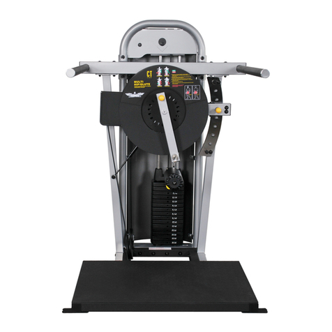
Inflight Fitness FT1000 User manual


FT1000 ASSEMBLYINSTRUCTIONS
IMPORTANT NOTICES
Readallwarning labels, theinstruction placardand thismanual before
attempting tousethis machine. Alwaysconsult your physician and an
exerciseprofessionalbeforebeginning anyexerciseprogram/regimen.
Beforeany testoruse checkforproper assemblyof themachine including
(but not limited to):bolts andotherhardwarefastenedproperly, cables in
pulley groovesand routed correctly. For safety useonly the topweightfor
the firstmachine movement.
Maintainyour machinein goodworkingorderby following themaintenance
schedule provided on theequipment.
Itisstronglyrecommended thata qualified dealer assemblethis
FT1000 FunctionalTrainer.
Shouldthere beanyquestionduringassembly contact your authorized Inflight
Fitnessdealer orcall direct to714 8214177.
Before beginning assemblyread thisinstruction manualthoroughly. Unpackand
verifyall partsand hardware quantitiesagainstthe partsandhardware lists.
Follow the assemblystepsin sequence. Failureto follow the order ofassembly
will result in disassemblylater and possibledamage to themachine components.
Thismanual includesthe instructionsforboth the standard 2:1 cablepull
functionaltrainerandthe optional4:1 cablepull functionaltrainer.
The3/8 nuts providedwith thismachine are “centerlocking .They provide a
more secureassembly thannylon lockingnuts.Pleasenotethey dorequire
more force to tightenthannylon lockingnuts.
1

FT1000 PARTSAND HARDWARE
PARTS
PLATINUM FRAMEPARTS
L/H MainFrameR/H Main FrameUpperCross Tube
LowerCross Tube
BLACK FRAMEPARTS
L/H ShroudR/H Shroud
CABLES AND PULLEYS- STANDARD
3 ½ Pulleys(10)4 ½ Pulleys(6)2:1 Cable (2)
2:1 Topweight Bracket(2)
CABLES AND PULLEYS 4:1 OPTION
3 ½ Pulleys(10)4 ½ Pulleys(10)4:1 L/H Upper Pulley Br’k’t
4:1 Topweight Br’k’t(2) 4:1 Cable (2) 4:1 R/H UpperPulley Br’k’t
MISCELLANEOUS
Guide Rods (4) LubeWeight StackCushions(4)
Weight LabelsManualTopWeight(2)
SelectorStem (2)PulleyCovers(6) Weight Pinw/ Lanyard(2)
10 –10# WeightPlates10 –5#Weight Plates
2

FT1000 PARTSAND HARDWARE
HARDWARE PACKS
DESCRIPTION QUANTITY
Bolts2:1 4:1
3/8 x4 ¼ 22
3/8 x3 ¾ 88
3/8 x3 ¼ 02
3/8 x2 ¾ 22
3/8 x2 ½ 04
3/8 x2 22
3/8 x1 ¾ 1212
Screws
¼ x ¼ Button HeadScrews10
Washers
3/8 Flat Washers3244
3/8 Curved Washers16
¼ Flat Washer 10
1
Nuts and Miscellaneous
3/8 Nuts2220
3

FT1000 ASSEMBLYINSTRUCTIONS
MAINSTRUCTUREASSEMBLY
NOTE:
THE L/H AND R/H MAIN FRAMES OFTHEFT1000AREHEAVY.
THEFRAMESARE TALLAND NARROW AND WILL BE UNSTABLE UNTIL
BOLTED TOGETHERWITH THE CROSS BRACES.
DO NOT STAND A FRAME UP AND THEN LEAVE ITUNATTENDED.
A. Do not fullytighten theboltsuntil after StepB.Youwill need the boltstobe
looseto align the componentsforassembly.
Standthe L/H MainFrameand assembletheLower CrossTube (no hooks)to
the lower two holesin the round tube usingtwo 3/8 x3 ¾ bolts, fourcurved
washers,and twolocknuts.
Stand the R/H Main Frame. Takecare with theStep.AligntheR/H Main
Upright with theLower CrossTube and assemble using two 3/8 x3 ¾ bolts,
four curved washersand two locknuts.
Assemble theUpper CrossBrace (with hooks)to theMain Uprightsusing
four 3/8 x3 ¾ bolts,eightcurvedwashers,and four locknuts.Donot fully
tighten theboltsatthistime.
B. Assemble the Pull-up Bar tothe L/H and R/H Main Uprightsusing 4 –3/8 x2
¾ bolts, 8 –3/8 flat washers,and4 –3/8 nuts.Two of the boltsare pre-
installed andjust need to have thenutsremoved. Checkthefit of theCross
TubesandPull-Up Bar and tightenalltheboltsatthistime.
C. Adjustthe threadedfoot down to touch the floor. Securebytighteningthe
jamnut
D. Loosenthe 3/8 boltsatthetopofthe guide rods.Leanthe guiderodsto the
insideof themachine andslideoffthetopweight/selector stemassembly.
4


FT1000 ASSEMBLYINSTRUCTIONS
CABLE AND TOPWEIGHTASSEMBLY
2:1STANDARD ASSEMBLY
E. Disassemble theselector stemfromeach topweightbyremovingthe 7/16
sockethead cap screw. Re-assembleeachselectorstemandtopweightto a
2:1 Topweight Bracketusing thesame 7/16 screw.
F. Place a2:1 cableunder thegroove of a4 ½ Pulley. Place the pulleyintoa
2:1 Topweight Bracketwith theloop end of thecable on thesamesideof the
topweightasthe socket head cap screw. Assemble the pulleyto the2:1
Topweight Bracket using one3/8 x2 bolt, two flat washers,andone locknut.
Repeat for thesecondcable andtopweight assembly.
4:1OPTION ASSEMBLY
G. Disassemble the selector stem from eachtopweightby removingthe 7/16
sockethead cap screw. Re-assembleeachselectorstemandtopweightto a
4:1 Topweight Bracketusing thesame 7/16 screw.
H. Place the loopend of one 4:1cable underthe groove ofa 4 ½ Pulley.Place
the pulleyinto theL/H slot ofoneof the 4:1TopweightBracketswith theloop
endofthecableonthe sameside of the topweightasthesocket headcap
screw.Placethethreadedendofthecableunderthe grooveofa4 ½ Pulley.
Place the pulleyinto theR/H slot ofthe Topweight Bracket with thethreaded
endout the opposite side of the topweight. Thisisthe R/H Topweight
Assemblypictured.
Place the loop endofthe other 4:1cablein the grooveofa 4 ½ Pulley.
Place the pulleyinto theR/H slot ofoneoftheother 4:1 Topweight Bracket
withthe loopend ofthe cableonthesameside of the topweightasthe socket
head capscrew.Placethethreaded end of thecable underthe groove ofa
4 ½ Pulley. Place thepulleyinto the L/H slotof the Topweight Bracket with
the threadedend outthe opposite side of thetopweight.
Assemble thepulleystoeach4:1 Topweight Bracket using one3/8 x3 ¼
bolt, two flat washers, andone locknut. Thisisthe L/H TopweightAss’y.
I. Placethecenter of each4:1cable over a 4 ½ Pulleyand install into the
UpperPulleyBracketthat correspondswith the cablerouting intheTopweight
Bracket. Use one 3/8 x2 bolt, two flat washersand onelocknuttosecure
each pulley.
6


FT1000 ASSEMBLYINSTRUCTIONS
WEIGHTSTACK ASSEMBLY
K. Place one weight stack cushion oneach Guide Rodandslidedown to the
base. Applylubricantto theGuideRodsfromthe weight stack cushionsto
the topsoftheGuideRods.
Makingsure thatthe recessfor theweightlabelsisfacing inside the machine
andthatthe threepadsare facing down, slide onto theGuideRods: 10 –10lb.
Weightsandthen10- 5lb.Weights(standard 150lb.weight stacks –optional
stackshave their own configuration).Place the Top Weight and Cable onthe
Guide Rods with the drilled hole facing the machineand slide down to the
stack.
Standthe weightstack and guiderodsback upand threadthe3/8 boltsdown
into theguide rods tosecure.
STEPL. AND M. ARE FOR THE 4:1 OPTION ONLY
L. Place one weight stack cushion oneach Guide Rodandslidedown to the
base. Applylubricantto theGuideRodsfromthe weight stack cushionsto
the topsoftheGuideRods.
Makingsure thatthe recessfor theweightlabelsisfacing inside the machine
andthatthe threepadsare facing down, slide onto theGuideRods: 10 –10lb.
Weightsandthen10- 5lb.Weights(standard 150lb.weight stacks –optional
stackshave their own configuration).Place the Top Weight and Cable onthe
Guide Rods with the drilled hole facing the machineand slide down to the
stack. Leaveenough cableslackforthe UpperBracket.
Standthe weightstack and guiderodsback upand threadthe3/8 boltsdown
into theguide rods tosecure.
M. Install the UpperPulleyBracketsbetween the guide rods,below the square
tube using two 3/8 x2 ½ bolts,fourflatwashersand two locknutsfor each
side.
AT THISTIME ITIS RECOMMENDED TO CHECK:
Arethe loop endsofthecables tothe inside ofthe machine?
Arethe threaded endsofthe cables to the outside of the machine?
Arethe UpperBrackets orientedsothat the cables do notcrossthe path of
the weightstack? (4:1option only)
8


FT1000 ASSEMBLYINSTRUCTIONS
THE FOLLOWING CABLE ROUTING APPLIES FOR BOTH THE STANDARD
2:1AND THE 4:1 OPTION FUNCTIONALTRAINER
N. Route the threadedend of the cableover a3½ Pulley. Attach thePulley,
cable,andaPulley Cover to the angledwelded postlocatedabovethe guide
rodsusingone 3/8 x1 ¾ bolt and one3/8 flat washer. Orient the tab of the
Pulleycover abovethePulley.
O. Route thecableforwardbetween the pulleyplateslocatedatthe obround
tube. Routethethreadedcable endinside thetube,downandout the
opening at thebottomtaking care not toscrape thecable’scoating.Installa
3 ½ pulley under the cable betweenthe platesatthetop of theobround tube
usingone 3/8’x2 bolt,twoflat washers, andonelocknut.
P. Place a3 ½ Pulley over the cablewhere itexitsthe tube andinstallit
between theplatesusing one3/8’x 2 bolt, two flat washers,andone locknut.
Q. Route the threadedendofthe cableupto the threaded postat thebottomof
the PulleyCarriageand install. Donottighten thejamnut until the cable is
completely routed.Use thethreaded endto adjustthecable tensionand then
tighten thejamnut.
R. Route theloop endofthecable upto thewelded postlocatedabove the
guiderods.Place thecable overa 3 ½ Pulleyand attach the Pulleyhere
withaPulley Cover using one3/8 x1 ¾ bolt andoneflat washer.Orientthe
tab of the PulleyCover above the Pulley.
S. Continuethecable forward tothe weldedpost locatedabovethe chrome
selectortube. Place thecable overa 3 ½ Pulleyand attach the Pulleyhere
withaPulley Cover using one3/8 x4 ¼ bolt,two flatwashers,and one nut.
Orientthe tab ofthe PulleyCoverabove the Pulley.
T. Install a4 ½ Pulley between theplates of the PulleyCarriagein the lower
position usingone 1 ¾ bolt,two flat washers,and onelocknut.Placethe
loopend off thecable undera 4 ½ Pulleyand install inthe upper position
usingone 3/8 x1 ¾ bolt, two flat washersand one locknut.
10


FT1000 ASSEMBLYINSTRUCTIONS
SHROUDS
U. Install the L/H and R/H Shroudsusingtwenty ¼ flatwashersand twenty ¼
screws. Theshorter side of the Shroudattachestothethreaded tabswelded
onto the round tube at the rear of the machine.
TRANSFER LABELS
V. Place the PulleyCarriageatthe lowestposition.It isrecommendedto do the
sidewith thestepfirst.
Thepositionsnumber1 through 24 startingwith 1 atthe bottom. There are
three labelsforeachset ofposition labels.
Peel the transferlabelwith numbers1-8from the paper backing.
Locatethe label verticallyso that thebottomof the number 1 circle iseven
withthe top of the square tubeat therear ofthe PulleyCarriage. Locate the
labelhorizontallyevenlyspaced intheflatarea of theobround tube.
Placethenextnumbered transferlabelsaboveand inline with the firstlabel.
Pressthe roundnumbered labelsto thetube to ensure theyadhere. Peel off
the clear plasticprotective coversleavingthe roundyellow labels.
W. AttachWeightLabelsinrecessprovided on front of Weight Plates. Allthe
recessesshould bealignedand to theright asyou face the weight stack.
12

Table of contents
Other Inflight Fitness Fitness Equipment manuals
Inflight Fitness
Inflight Fitness VANGUARD User manual

Inflight Fitness
Inflight Fitness VANGUARD User manual

Inflight Fitness
Inflight Fitness Liberator User manual

Inflight Fitness
Inflight Fitness Multi-Lat/Arm User manual

Inflight Fitness
Inflight Fitness SMITH MACHINE User manual
Inflight Fitness
Inflight Fitness CT-MHP User manual
Inflight Fitness
Inflight Fitness MEC User manual

Inflight Fitness
Inflight Fitness MULTI-FLY/DELT User manual

Inflight Fitness
Inflight Fitness Mab User manual
Inflight Fitness
Inflight Fitness CT-ILPC User manual