INGENIA Pluto User manual

13-Apr-2016 12:09Date:
4Version:
Pluto Servo Drive
Product Manual
Table of Contents

Table of Contents
1 Manual revision History 4
2 Preliminary notes 5
3 Safety Information 6
3.1 Warnings 7
3.2 Precautions 7
4 Product Description 7
4.1 Specifications 8
4.2 Hardware revisions 11
4.3 Power and current ratings 12
4.3.1 Power losses calculation (heat dissipation) 13
4.3.2 Current ratings 13
4.3.3 System temperature 14
4.3.4 Dynamic application (non-constant current) 14
4.4 Pluto architecture 15
5 Connectors 15
5.1 CAN interface connector 17
5.2 Feedbacks connector 18
5.3 I/O connector 19
5.4 Supply and shunt connector 20
5.5 Motor connector 21
5.6 USB connector 21
5.7 Mating connectors 22
5.7.1 CAN interface mating connector 22
5.7.2 Feedbacks mating connectors 22
5.7.3 I/O mating connectors 23
5.7.4 Motor mating connector 24
5.7.5 Supply and shunt mating connector 24
5.7.6 USB mating connector 25

5.8 EtherCAT variant pinout 25
5.8.1 EtherCAT input and output connector 26
6 Wiring and Connections 27
6.1 Power supply wiring 28
6.1.1 How to dimension the power supply 28
6.1.2 Recommended power supply connection 29
6.1.3 Simplified battery supply connection 30
6.1.4 Connection of multiple drivers 30
6.1.5 Power supply wiring recommendations 31
6.2 Motor output wiring 32
6.2.1 AC and DC brushless motors 32
6.2.2 DC motors and voice coils actuators 33
6.2.3 Stepper motors 33
6.2.4 External shunt resistor 34
6.2.5 Motor wiring recommendations 37
6.3 Feedback connections 39
6.3.1 Digital encoder interface 39
6.3.2 Digital Halls interface 43
6.3.3 Analog Halls interface 45
6.3.4 Analog input feedback - Potentiometer 46
6.3.5 PWM encoder interface 49
6.3.6 DC tachometer 52
6.3.7 Feedback wiring recommendations 52
6.4 IO connections 53
6.4.1 Low speed (LS) single ended digital inputs interface 54
6.4.2 High speed (HS) digital inputs interface 56
6.4.3 Analog inputs interface 59
6.4.4 Digital outputs interface 61
6.4.5 Torque off input 65
6.5 Command sources 66
6.5.1 Network interface 67
6.5.2 Standalone 67
6.5.3 Analog input 67
6.5.4 Step and direction 68
6.5.5 PWM command 69
6.5.6 Encoder following or electronic gearing 72
6.6 Communications 73
6.6.1 CAN interface 74
6.6.2 USB interface 76
6.6.3 EtherCAT interface 76

7 Signalling LEDs 78
7.1 Power and motor signalling LEDs 79
7.2 CAN signalling LEDs 79
7.3 EtherCAT signalling LEDs 80
7.3.1 EtherCAT status LED 81
7.3.2 EtherCAT in-connector LED 81
8 Software 82
8.1 Installing MotionLab Configuration Software 83
8.1.1 Before you begin 83
8.1.2 Hardware Installation: 83
8.1.3 Software Installation and Drive Communication Setup: 83
8.2 Updating your drive Firmware 84
8.3 Configuring your drive 85
9 Dimensions 85
9.1 Standard version 86
9.2 EtherCAT version 86
10 Disclaimers and limitations of liability 87
Manual revision History

Product Manual
5/88
Manual revision History
Revision Release Date Changes PDF
v1 January 2013 Initial Version --
v2 April 2014 Update for hardware revision 1.1.0R Download
v3 March 2016 Several improvements after revision 2.0.1R Download
v4 April 2016 Added EtherCAT information. Structure improvements.
Preliminary notes

Product Manual
6/88
Preliminary notes
Please refer to for information on previous hardware revisions and changes.Hardware revisions
Please refer to the for the most up to date revision.online manual
Safety Information

Product Manual
7/88
Safety Information
Read carefully this chapter to raise your awareness of potential risks and hazards when working with the
Pluto Servo Drive.
To ensure maximum safety in operating the Pluto Servo Drive, it is essential to follow the procedures
included in this guide. This information is provided to protect users and their working area when using the
Pluto Servo Drive, as well as other hardware that may be connected to it. Please read this chapter carefully
before starting the installation process. Please also make sure all system components are properly
grounded.
Warnings
The following statements should be considered to avoid serious injury to those individuals performing the
procedures and/or damage to the equipment:
To prevent the formation of electric arcs, as well as dangers to personnel and electrical contacts,
never connect/disconnect the Pluto Servo Drive while the power supply is on.
Power cables may be exposed to high voltages, even when the motor is not in motion. Disconnect
the Pluto Servo Drive from all power sources before proceeding with any possible wiring change.
After turning off the power and disconnecting the equipment power source, wait at least 1 minute
before touching any parts of the controller that are electrically charged or hot (such as capacitors or
contacts).
Precautions
The following statements should be considered to avoid serious injury to those individuals performing the
procedures and/or damage to the equipment:
The Pluto Servo Drive components temperature may exceed 75ºC during operation.
Some components become electrically charged when in operation.
The power supply connected to this controller should comply with the parameters specified in this
document.
When connecting the Pluto Servo Drive to an approved 10 V to 48 V power source, do so
DC DC
through a line that is separate from any possible dangerous voltages, using the necessary insulation
in accordance with safety standards.
High-performance motion control equipment can move rapidly with very high forces. Unexpected
motion may occur especially during product commissioning. Keep clear of any operational
machinery and never touch them while they are working.
Do not make any connections to any internal circuitry. Only connections to designated connectors
are allowed.
All service and maintenance must be performed by qualified personnel.
Before turning on the Pluto Servo Drive, check that all safety precautions have been followed, as
well as the installation procedures.
Product Description
Product Manual
8/88
Product Description
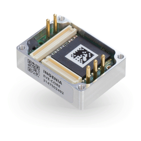
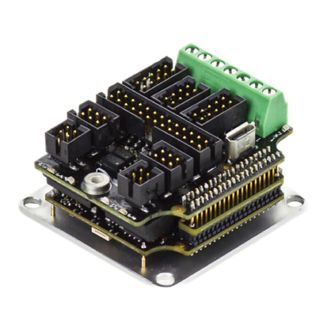
Pluto is a high performance closed loop servo drive controller suitable for DC brushed, steppers, voice
coils and brushless motors.
Its design includes multiple communication ports, enabling thus a wide choice of interfacing methods. Its
extended voltage operating range allows its use in several applications, and the small footprint and the
needless of an external heatsink allow the controller to be a valid OEM for critical-size applications.
The design also includes a wide variety of self protection mechanisms.
Specifications
There are 3 variants of the Pluto, specs are shown next.
Electrical and power specifications
Variant PLU-1/48 (HS) PLU-5/48 (STD) PLU-8/48 (EXT)
Supply voltage 10 V to 48 V
DC DC
Transient peak
voltage
60 V
Internal DC bus
capacitance
112 µF
Minimum motor
inductance
200 µH
Maximum phase
peak current
2 ARMS (5 s) 10 ARMS (5 s) 16 ARMS (5 s)
Maximum phase
continuous
current
1 ARMS 5 ARMS 8 ARMS
Current sense
range
± 4.8 A ± 19.2 A ± 32 A
Current sense
resolution
9.35 mA/count 37.39 mA/count 62.32 mA/count
Cold plate No
Power connectors Pluggable terminal
Standby power
consumption
1.5 W (max)
Efficiency > 97% at the rated power and current

Product Manual
9/88
Electrical and power specifications
Motion control specifications
Supported motor
types
Rotary or linear brushless (trapezoidal and sinusoidal)
DC brush
Voice coil
2 phases bipolar stepper
3 phases stepper
Power stage PWM
frequency
40 kHz (default)
80 kHz (high PWM frequency, )configurable
Current sensing On phases A, B and C using 3 terminal shunt resistors.
Accuracy is ± 1% full scale.
10 bit ADC resolution.
Sensors for
commutation
(brushless
motors)
Digital halls (Trapezoidal)
Analog halls (Sinusoidal / Trapezoidal)
Quad. Incremental encoder (Sinusoidal / Trapezoidal)
PWM encoder (Sinusoidal / Trapezoidal)
Analog potentiometer (Sinusoidal / Trapezoidal)
Sensors supported
for servo loops
DC tachometer
Digital halls
Analog halls
Quad. Incremental encoder
PWM encoder
Analog potentiometer
Supported target
sources
Network communication – (µUSB connector)USB
Network communication – (Isolated, self-supplied, CiA-301, CiA-CANopen
303, CiA-305, CiA-306 and CiA-402 compliant)
Network communication – EtherCAT (CoE)(Option)
Standalone (execution from Internal EEPROM memory)
Analog input (±10 V or 0 V to 5 V)
Step and Direction (Pulse and direction)
PWM command
Encoder follower / Electronic Gearing

Product Manual
10/88
Electrical and power specifications
Inputs/outputs and protections
Inputs and
outputs
2 x non isolated single ended digital inputs. GDI1, GDI2 (5 V TTL logic, 24 V
tolerant)
2 x non isolated high speed differential digital inputs. HS_GPI1 Pulse,
HS_GPI2 Direction (5 V logic, 24 V tolerant)
1 x (±10 V) differential analog input (12 bits). AN_IN2. (24 V tolerant)
1 x 0 V... 5 V single ended analog input (12 bits). AN_IN1. (24 V tolerant)
2 x Open open drain digital outputs with a weak pull-up to 5 V. (1 A short-
circuit and over-current rugged)
Protections User configurable:
Bus over-voltage
Bus under-voltage
Over temperature
Under temperature
Over current
Overload (I t)
2
Short-circuit protections:
Phase-DC bus
Phase-phase
Phase-GND
Mechanical limits for homing functions
Hall sequence/combination error
ESD & EMI protections: ESD protections are available in all inputs, outputs
and communications. All inputs, outputs, feedbacks include noise filters.
Inverse polarity supply protection (bidirectional)
High power transient voltage suppressor for short braking: A TVS diode
(1500 W peak) protects the circuitry from the voltage transients events
Encoder broken wire (for differential quadrature encoders only).
Communications
USB µUSB (2.0) connector.
CANopen Yes.
EtherCAT Option.

Product Manual
11/88
Electrical and power specifications
Environmental and mechanical specifications
Variant PLU-1/48 PLU-5/48 PLU-8/48
Ambient air
temperature
-40 ºC to +50 ºC (operating)full current
+50 ºC to +100 ºC (operating)current derating
-50 ºC to -40ºC and 100ºC to +125 ºC (non-operating)
Maximum
humidity
5% - 85% (non-condensing)
Dimensions 60 mm x 60 mm x 15 mm
Weight (exc.
mating
connectors)
35 g
Hardware revisions
Hardware
revision*
Description and changes
1.0.1R First product release.
1.1.0R Changes from previous version:
CAN connector change from 4 ways to 3 ways (Phoenix Contact 1937509). PE pin is
removed from connector. PE connection should be made with the plated mounting
holes
CAN LEDs position change
Supply connector change from 4 ways to 3 ways (Phoenix Contact 1937509). PE pin is
removed from connector. PE connection should be made with the plated mounting
holes
IO connector change TE Micro-Match model 8-188275-6. Same pinout except 1
change: +5.0 V output is added at pin 16. (Version 1.0.1 had this pin connected to
GND)
Feedback connector change to TE Micro-Match model 8-188275-2. Pinout remains
identical to version 1.0.1R
Increased USB port electrical robustness and noise immunity
Readjusted power stage elements to minimize electromagnetic emissions

Product Manual
12/88
Hardware
revision*
Description and changes
2.0.1R Changes from previous version:
Added EtherCAT connectivity
PCB and PCA modifications to improve manufacturing reliability
Changed rounded corners radius for aesthetic reasons
High-speed (HS) digital inputs interface are pre-biased to allow easy wiring in single
ended applications
Added STO (Safe Torque Off) as a mounting option upon demand
2.1.0 Changes from previous version:
Changed some components due to obsolescence
Same transistors are mounted for all the current variants (better performance).
Removed some unnecessary components
CAN connector changed to FCI 20020110-C031A01LF (green) to avoid confusion with
the supply and shunt connector
Silkscreen improvements
*Hardware revision is screen printed in white below motor connector, on the bottom of the Pluto.
Power and current ratings
The Pluto is capable of providing the nominal current from -10ºC to 50ºC ambient air temperature without
the need of any additional heatsink or forced cooling system. From 50ºC to 80ºC of ambient temperature a
current derating is needed to avoid a system overtemperature.
Excessive power losses lead to over temperature that will be detected and cause a the driver to turn off.
The system temperature is available in and is measured on the power stage. The EMCL registers
temperature parameter that can be accessed from USB 2.0 or CAN interface does not indicate the air
temperature. Above 110ºC the Pluto automatically turns off the power stage and stay in fault state
avoiding any damage to the drive. A Fault LED will be activated and cannot be reset unless temperature
decreases.
Current foldback based on temperature
Driver safety is always ensured by its protections. However, power losses and temperature limit
the allowable motor current.
Future will allow an automatic current fold-back based on temperature. versions of firmware
This means the current will be reduced before an over-temperature occurs. Stay tuned for
upgrades!
Some parts of the Pluto exceed 110ºC when operating, especially at high load levels.
and wait at least 5 minutes after turn off to allow a Do not touch the driver when operating
safe cool down.

Product Manual
13/88
Power losses calculation (heat dissipation)
Operation of the Pluto causes power losses that should be transferred to the surrounding environment as
heat. Heat dissipation depends on various parameters. Principally:
Motor RMS current: positive correlation.
DC bus voltage: positive correlation.
Other less relevant parameters affect also the power loss but are not considered in the graphs:
Air temperature, higher power semiconductor temperatures reduce their efficiency.
Motor speed. Faster motor speeds result in higher overall power loss since the input current is
greater. This increases conduction losses on the reverse polarity protection circuitry.
Current ratings
The Pluto Servo drive has no cold plate, so the board itself is the heatsink. Power losses cause the driver to
increase its temperature following the this formula:
Since T < 110ºC for safe operation, the maximum current rating can be calculated.
P
The thermal impedance of the Pluto will vary according to:
Air flow around the driver.
Position (vertical allows natural convection).

Product Manual
14/88
Current derating
The current derating graph is indicative and is based on thermal tests performed in a climatic
room where there was enough room for natural air convection. Each application may reach
different ratings depending on the installation, ventilation or housing.
System temperature
The system temperature is measured near the power stage. Between power phases. The temperature
parameter that can be accessed from USB 2.0 or CAN bus indicates the board temperature (not the air
temperature) and should not exceed 110ºC. Above 110ºC the Pluto automatically turns off the power stage
and stays in fault state avoiding any damage to the drive.
Next image shows the power stage surface at maximum load and air temperature in a 3 phase
application.
The driver is getting hot even at 0 current!
This is normal. Pluto power stage includes high power MOSFET transistors which have parasitic
capacitances. Switching them fast means charging and discharging those capacitors thousands
of times per second which results in power losses and temperature increase even at 0 current!
Recommendation: when motor is off, exit motor enable mode which will switch off the
power stage.
Dynamic application (non-constant current)
The Pluto has a big thermal inertia that allows storing heat during short current pulses (exceeding nominal
current) without causing an over temperature.
This allows achieving high peak current ratings without need of additional heatsink.
Easy approach (quadratic mean of current)
For most systems where the cycle time is shorter than 3 τ (thermal time constant) the current can be
calculated as the quadratic mean of the current during the full cycle.
The load cycle can be simplified as different constant currents during some times:

Product Manual
15/88
T: Full cycle period.
I : Current during t1
1
I : Current during t2
2
I : Current during tn
n
Dynamic model
For systems with a time > than 3 τ the dynamic model should be used.
Instead of considering thermal resistances you should consider the thermal impedance. The Pluto model
can be simplified as a 2nd order.
Pluto architecture
Connectors

Product Manual
16/88
Connectors
Next figures show PlutoServo Drive connectors position, functionalities and pinout. For EtherCAT
connectors pinout see .below

Product Manual
17/88
CAN interface connector
The CAN interface connector is a 3 pin pluggable terminal block with 3.5 mm pitch.
Pin numbers and connectors pinout are shown below:
Pin Name Description
1 GND CAN ground
2 CANL CAN bus line dominant low

Product Manual
18/88
Pin Name Description
3 CANH CAN bus line dominant high
Please note that both CAN and DC Bus use the same type of connector. Please check you are
connecting your power supply to the right connector.
This connector has changed from previous hardware revisions. Please see Hardware revisions
for more information.
Feedbacks connector
Pluto has a 12 pin TE Micro-Match connector for motor feedbacks. Part number . TE 1-338068-2
Polarization hole on PCB indicates pin 1 and ensures correct cable position. See for Feedback connections
more information about different feedbacks wiring.
Pin numbers and connectors pinout are shown below.
Pin Name Description
1 +5V_OUT 5 V @ 250mA supply for feedbacks
2 GND Ground connection
3 ENC_A+ Single ended digital encoder: A input
Differential digital encoder: A+ input
4 ENC_A- Differential Encoder: A- input
5 ENC_B+ Single ended digital encoder: B input
Differential digital encoder: B+ input
6 ENC_B- Differential Encoder: B- input
7 ENC_Z+ Single ended digital encoder: Index input
Differential digital encoder: Index+ input

Product Manual
19/88
Pin Name Description
8 ENC_Z- Differential Encoder: Index- input
9 GND Ground connection
10 HALL_1 Analog Halls: A input
Digital Halls: A input
11 HALL_2 Analog Halls: B input
Digital Halls: B input
12 HALL_3 Analog Halls: C input
Digital Halls: C input
This connector has changed from previous hardware revisions. Please see Hardware revisions
for more information.
For Sin-Cos encoder see the .Nix Servo Drive
I/O connector
Pluto has a 16 pin TE Micro-Match connector for inputs and outputs. Part number . See 1-338068-6
and for wiring information. Polarization hole on PCB indicates pin 1 Potentiometer PWM encoder interface
and ensures correct cable position.
Pin numbers and connectors pinout are shown below.
Pin Name Description
1 HS_GPI2+ / DIR+ High speed digital differential input 2+
Command source: Direction+ input
2 HS_GPI2- / DIR- High speed digital differential input 2-
Command source: Direction- input
3 GND Ground

Product Manual
20/88
Pin Name Description
4 GPO2 Digital output 2
5 GPO1 Digital output 1
6 GND Ground
7 HS_GPI1+ / PULSE+ / PWM+ High speed digital differential input 1+
Command source: Pulse+ input
Feedbacks: PWM+ input
8 HS_GPI1- / PULSE- / PWM- High speed digital differential input 1-
Command source: Pulse- input
Feedbacks: PWM- input
9 GND Ground
10 AN_IN1 Single ended analog input 1
11 AN_IN2- Differential analog inverting input 2
Single ended analog input 2 ground
12 AN_IN2+ Differential analog non inverting input 2
Single ended analog input 2
13 GND Ground
14 LS_GPI2 Low speed digital single ended input 2
(Could be safe torque off input on request, please contact us)
15 LS_GPI1 Low speed digital single ended input 1
16 +5V_EXT +5V 200mA max output (shared with feedback connector)
Note: In previous Pluto versions (1.0.1R) which had CLIK-Mate connectors this pin was connected
to GND. Please see for more information.Hardware revisions
I/O connector pinout is shared with , , and servo drives, which allows Nix Jupiter Hydra Neptune
using the with Pluto.IO starter kit
Supply and shunt connector
The supply and shunt connector is a 3 pin pluggable terminal block with 3.5 mm pitch. See Power supply
for power wiring information. Details on shunt operation see .wiring External Shunt Resistor
Pin numbers and connectors pinout are shown below:
Table of contents
Other INGENIA Servo Drive manuals

INGENIA
INGENIA Triton Go User manual

INGENIA
INGENIA Everest XCR User manual

INGENIA
INGENIA Nix series User manual

INGENIA
INGENIA Titan GO User manual

INGENIA
INGENIA Neptune User manual

INGENIA
INGENIA Titan GO User manual

INGENIA
INGENIA Jupiter JUP-20/80 User manual

INGENIA
INGENIA Triton Core User manual

INGENIA
INGENIA Everest XCR User manual

INGENIA
INGENIA Everest CORE User manual
Popular Servo Drive manuals by other brands

CS-Lab
CS-Lab simDrive Series quick start

KEBCO
KEBCO COMBIVERT S6 Series Instructions for use

Oriental motor
Oriental motor AZX Series operating manual

Panasonic
Panasonic MINAS-A6 Series Specifications

Moons'
Moons' Applied Motion Products TXM34X B Series Hardware manual

Beckhoff
Beckhoff AX2500 Series Assembly, Installation, Setup