EN-6 22207666 Rev. C
EN
If you will be using synthetic compressor lubricant, all
downstream piping material and system components must be
compatible. Refer to the following material compatibility list.
If there are incompatible materials present in your system, or
if there are materials not included in the list, contact Ingersoll
Rand for recommendations.
SYNTHETIC COMPRESSOR LUBRICANT MATERIAL COMPATIBILITY
LIST
SUITABLE :
FKM (Fluoroclastomer), PTFE, Epoxy (Glass Filled), Oil Resistant
Alkyd, Fluorosilicone, Fluorocarbon, Polysulde, 2-Component
Urethane, Nylon, POM (Polyoxymethylene/Polyacctel), High
Nitrile Rubber (Buna N. NBR more than 36% Acrylonitrile),
Polyurethane, Polyethylene, Epichlorohydrin, Polyacrylate, Melamine,
Polypropylene, Baked Phenolics, Epoxy, Modied Alkyds (® indicates
trademark of DuPont Corporation).
NOT RECOMMENDED :
Neoprene, Natural Rubber, SBR Rubber, Acrylic Paint, Lacquer,
Varnish, Polystyrene, PVC, ABS, Polycarbonate, Cellulose Acetate,
Low Nitrile Rubber (Buna N. NBR less than 36% Acrylonitrile), EPDM,
Ethylene Vinyl Acetate, Latex, EPR, Acrylics, Phenoxy, Polysulfones,
Styrene Acrylonitrile (San), Butyl.
All compressed air systems generate condensate which
accumulates in any drain point (e.g. tanks, lters, drip legs,
aftercoolers, dryers). This condensate contains lubricating
oil and/or substances which may be regulated and must be
disposed of in accordance with local, state, and federal laws and
regulations.
GENERAL REQUIREMENTS
The piping, ttings, air receiver tank, etc. must be certied safe for at least
the maximum working pressure of the unit. Use hard-welded or threaded
steel or copper pipes and cast iron ttings that are certied safe for the
unit’s discharge pressure and temperature. DO NOT USE PVC PLASTIC IN
THE COMPRESSED AIR DISCHARGE LINE. Use pipe thread sealant on all
threads, and make up joints tightly to prevent air leaks.
CONDENSATE DISCHARGE PIPING
If installing a condensate discharge line, the piping must be at least one
size larger than the connection, as short and direct as possible, secured
tightly and routed to a suitable drain point or waste container. Condensate
must be disposed of in accordance with local, state, and federal laws and
regulations.
If an aftercooler, check valve, block valve, or any other
restriction is added to the compressor discharge, install a
properly-sized ASME approved safety/relief valve between the
compressor discharge and the restriction.
INSTALLING ELECTRICAL WIRING
Electrical installation and service should be performed by a
qualied electrician who is familiar with all applicable local, state
and federal laws and regulations.
GENERAL
The motor rating, as shown on the motor nameplate, and the power
supply must have compatible voltage, phase and hertz characteristics.
WIRE SIZE
The electrical wiring between the power supply and electric motor varies
according to motor horsepower and other factors. Install adequately
sized power leads to protect against excessive voltage drop during
start-up. Refer to the National Electric Code (NEC) for information on
selecting the proper wire size and securing electrical connections. If you
connect additional electrical equipment to the same circuit, consider the
total electrical load when selecting the proper wire size. DO NOT USE
UNDERSIZE WIRE.
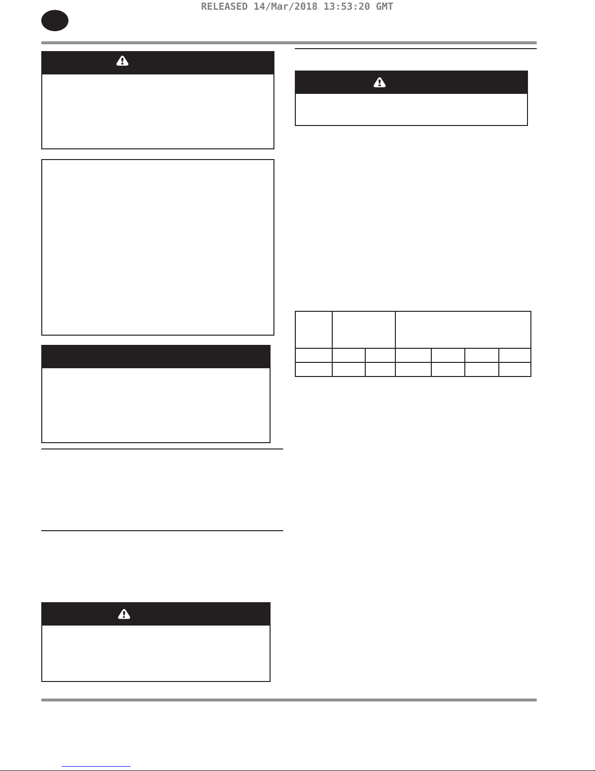
If wire size information is not available, the wire sizes shown in the
following wire selection chart can be used as a safe guide, if the distance
does not exceed 50 feet (15.3 m). For longer distances, consult and
electrical contractor or the local electric company for recommendations.
MOTOR
HP
SINGLE
PHASE
THREE
PHASE
115V 230V 200V 230V 460V 575V
5 4 (6) 8 (10) 10 (12) 12 (14) 14 (16) 14 16)
Wire sizes shown in AWG (SWG):
AWG =American Wire Gauge
SWG = British Imperial Standard Wire Gauge
MAGNETIC STARTER
If the motor installed on your unit has a motor reset button, it does not
require a magnetic starter. If the motor does not have this button and the
unit does not have a factory-installed starter, install a magnetic starter
with thermal overload protection. Follow the manufacturer’s instructions
for installation. Ingersoll Rand cannot accept responsibility for damages
arising from failure to provide adequate motor protection.
FUSES
Refer to the NEC to determine the proper fuse or circuit breaker rating
required. When selecting fuses, remember the momentary starting current
of an electric motor is greater than its full load current. Time-delay or “slow-
blow” fuses are recommended.
PRESSURE SWITCH
On units without a factory-installed pressure switch, wire a pressure switch
in accordance with the appropriate wiring schematic in the DIAGRAMS
section of this manual. Mount the pressure switch in accordance with the
manufacturer’s recommendations. The connecting line to the receiver tank
must be as short and direct as possible, and certied safe for at least the
maximum working pressure of the unit.
•
•
RELEASED 14/Mar/2018 13:53:20 GMT