Ingersoll-Rand FC2AO1SM User manual

Product Parts
Information
Liftchain Mining Air Hoist
Models
LC2A015SM, LC2A030DM, LC2A040SM, LC2A060SM, LC2A080DM, and
LC2A120DM
(Dwg. MHP2684)
Save These Instructions
Form MHD56309
Edition 2
June 2011
71455786
©2011 Ingersoll-Rand Company

Only allow Ingersoll Rand trained technicians to perform maintenance on this product. For additional information contact Ingersoll Rand factory or nearest
Distributor.
For additional supporting documentation refer to Table 1 ‘Product Information Manuals’ on page 2.
Manuals can be downloaded from www.ingersollrandproducts.com.
The use of other than genuine Ingersoll Rand replacement parts may result in safety hazards, decreased performance and increased maintenance and will invalidate all warranties.
Original instructions are in English. Other languages are a translation of the original instructions.
Refer all communications to the nearest Ingersoll Rand Office or Distributor.
Table 1: Product Information Manuals
Publication Part/Document Number Publication Part/Document Number
Product Safety Information Manual MHD56295 Product Maintenance Information Manual MHD56308
Product Information Manual MHD56307
TABLE OF CONTENTS
Description Page No.
Parts Ordering Information .....................................................3
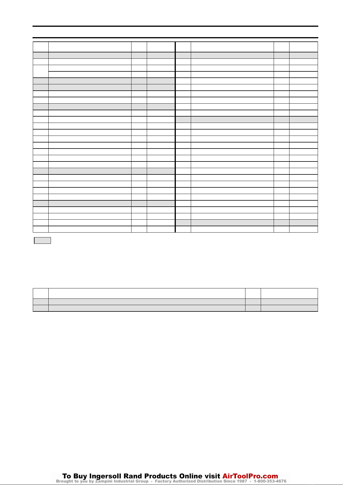
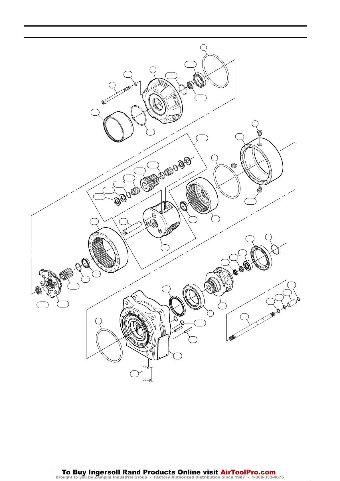
1.5 Ton Single and 3 Ton Double Powerhead and Disc Brake Assembly Drawing .......4
1.5 Ton Single and 3 Ton Double Powerhead and Disc Brake Assembly Parts List ......5
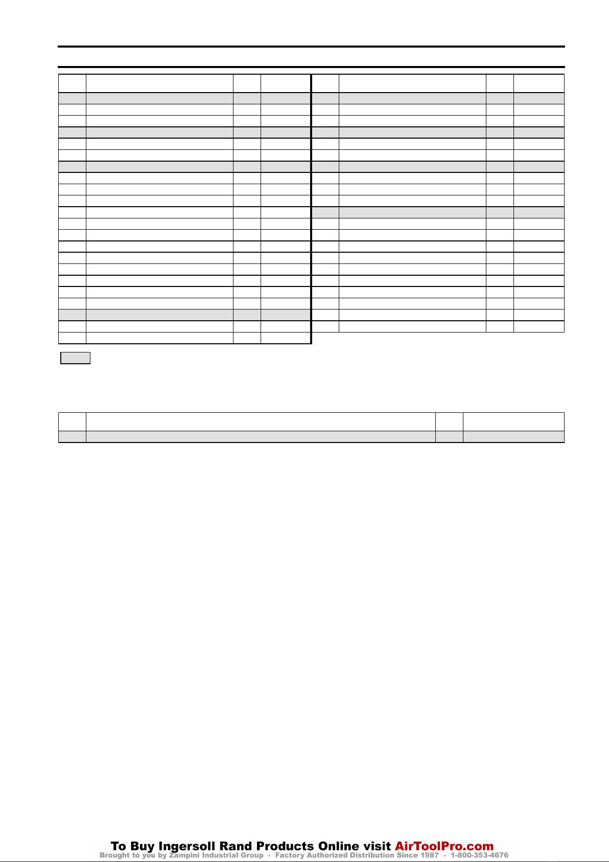
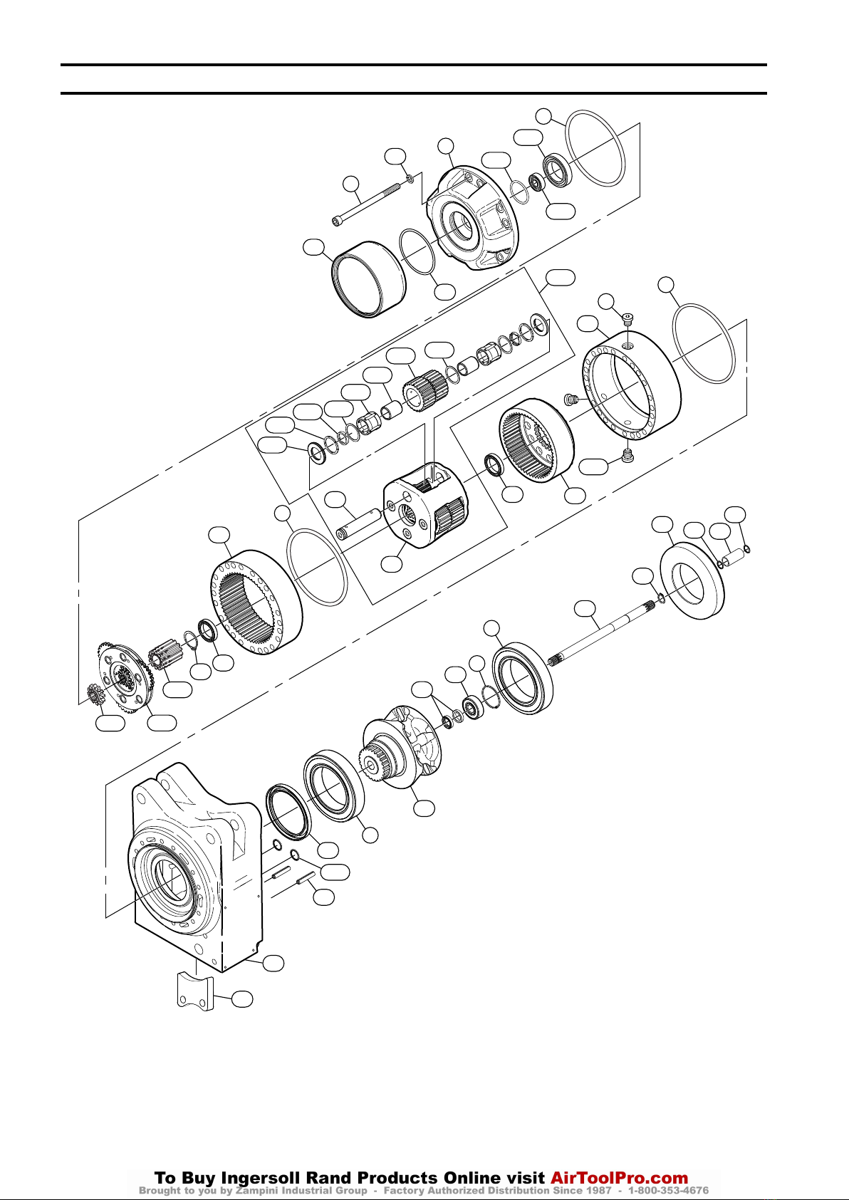
4 Ton Single and 8 Ton Double Powerhead Assembly Drawing ......................6
4 Ton Single and 8 Ton Double Powerhead Assembly Parts List .....................7
6 Ton Single and 12 Ton Double Powerhead Assembly Drawing .....................8
6 Ton Single and 12 Ton Double Powerhead Assembly Parts List ....................9
3.5 HP Motor Assembly Without Emergency Stop Adapter Drawing ................10
3.5 HP Motor Assembly Without Emergency Stop Adapter Parts List ...............11
3.5 HP Motor Assembly with Emergency Stop Adapter Drawing ....................12
3.5 HP Motor Assembly with Emergency Stop Adapter Parts List ...................13
6 HP Motor and Disc Brake Assembly Without Emergency Stop Adapter Drawing ....14
6 HP Motor and Disc Brake Assembly Without Emergency Stop Adapter Parts List ....15
6 HP Motor and Disc Brake Assembly with Emergency Stop Adapter drawing ........16
6 HP Motor and Disc Brake Assembly with Emergency Stop Adapter Parts List .......17
Two Function Pendant Control Assembly Without Emergency Stop Parts Drawing ...18
Two Function Pendant Control Assembly Without Emergency Stop Parts List ........19
Two Function Pendant Control Assembly with Emergency Stop Drawing ............20
Two Function Pendant Control Assembly with Emergency Stop Parts List ...........21
Top Hook Assemblies Drawing and Parts List ....................................22
1.5 and 3 Ton Bottom Block Assembly Drawing and Parts List .....................23
4, 6, 8 and 12 Ton Bottom Block Assembly Drawing and Parts List .................24
Bottom Hook Accessories Parts Drawing and Parts List ...........................25
Label and Tag Placement Assembly Drawing and Parts List .......................26
Dwg. Name Page No.
.
(Dwg. MHP2692) ..............................................................4
.
(Dwg. MHP3163) ..............................................................6
.
(Dwg. MHP3164) ..............................................................8
.
(Dwg. MHP3200) .............................................................10
.
(Dwg. MHP3201) .............................................................12
.
(Dwg. MHP3204) .............................................................14
.
(Dwg. MHP3205) .............................................................16
.
(Dwg. MHP3040) .............................................................18
.
(Dwg. MHP3039) .............................................................20
.
(Dwg. MHP3206) .............................................................22
(Dwg. MHP3203) .............................................................23
(Dwg. MHP3006) .............................................................24
(Dwg. MHP1431) .............................................................25
(Dwg. MHP3081) .............................................................26
2 Form MHD56309 Edition 2

PARTS ORDERING INFORMATION
These products are designed and constructed to provide long, trouble-free service. In
time it may be necessary to order and install new parts to replace those that have
been subjected to wear.
For your convenience and future reference, it is recommended that the following
information be recorded.
Model Number________________________________________________________
Serial Number________________________________________________________
Date Purchase________________________________________________________
When ordering replacement parts, please specify the following:
1. Complete model number and serial number as it appears on the data (name) plate.
2. Part number(s) and part description as shown in this manual.
3. Quantity required.
The data (name) plate is located on the product.
NOTICE
• Continuing improvement and advancement of design may cause changes to
this equipment which are not included in this manual. Manuals are
periodically revised to incorporate changes. Always check the manual edition
number on the front cover for the latest issue.
•Sections of this manual may not apply to your product.
• The use of other than genuine Ingersoll Rand replacement parts may result
in safety hazards, decreased performance and increased maintenance, and
will invalidate all warranties.
nReturn Goods Policy
Ingersoll Rand will not accept any returned goods for warranty or service unless prior
arrangements have been made and written authorization has been provided from the
location the goods were purchased.
Products that have been modified without Ingersoll Rand approval, mishandled or
overloaded will not be repaired or replaced under warranty. A printed copy of the
warranty that applies to this product is provided inside the back cover of the product
information manual or in some cases the parts manual.
nDisposal
When the life of the product has expired, it is recommended that
it be disassembled, degreased and parts separated as to
materials so that they may be recycled.
For additional information contact:
Ingersoll Rand
20017 72nd Avenue South
Kent, WA 98032 USA
Phone: (877) 584-0370
Fax: (206) 624-6265
or
Ingersoll Rand
Douai Operations
529, Avenue Roger Salengro
59450 Sin Le Noble, France
Phone: (33) 03-27-93-08-08
Fax: (33) 03-27-93-08-00
Form MHD56309 Edition 2 3

1.5 TON SINGLE AND 3 TON DOUBLE POWERHEAD AND DISC BRAKE ASSEMBLY DRAWING
89
10 11
25
23
12
13
14
15
16
17
18 19
24
6
27
20
8
29
30
41
31
34
36
48
43
42
37
38
10
39
68
10
7
6
1
61
7
62
63
64
6
65 66
67
72
1
5
6
7
4
88
89
93 94
95
96
151
341
(Dwg. MHP2692)
4 Form MHD56309 Edition 2

1.5 TON SINGLE AND 3 TON DOUBLE POWERHEAD AND DISC BRAKE ASSEMBLY PARTS LIST
Item
No. Description
of Parts Total
Qty Part
Number Item
No. Description
of Parts Total
Qty Part
Number
• 1 Plug 2 6511–0441 • 37 Oil Seal 1 5801–9830
4 Capscrew 5 4133–2506 38 Bearing 1 5005–0002
5Reduction Gear End Cover (old style) 1 9644–3008 39 Bearing 1 5005–0009
Reduction Gear End Cover (new style) 1 9644–0817 41 Capscrew 3 4132–9406
• 6 ‘O’ Ring 4 5823–5229 42 Nut 3 75583M
• 7 Gasket 3 9644–1048 43 Pin 2 4600–2816
8 Bearing 2 5080–0009 48 Support 1 9644–3289
9 Retainer Ring 1 4770–3032 61 Brake Housing (Note 2) 1 9644–0574
• 10 Retainer Ring 3 4770–0015 62 Capscrew 3 4130–1106
11 Bearing 1 5000–0002 63 Piston 1 9644–1014
12 Spacer 3 9644–1047 • 64 ‘O’ Ring 1 5823–5129
13 Planetary Gear 3 9644–1002 65 Splined Hub 1 9644–1013
14 Bearing Ring 6 5636–2041 66 Friction Plate (Note 2) 3 6302–8241
15 Needle Bearing 6 5656–2141 67 Drive Plate (Note 2) 5 6302–8341
16 Planet Axle 3 9644–1046 68 Brake Reaction Plate 1 9644–1015
17 Planetary Carrier 1 9644–1006 72 Friction Plate with Spring Clips (Note 2) 3 9644–1552
18 Bearing 1 5080–0005 88 Muffler Assembly 1 3644–0567
19 Ring Gear 1 9644–1003 89 Ring Flat (Note 3) 1 9644–0566
• 20 Oil Seal 1 5801–2130 93 Expansive Ring (Note 3) 1 4789–8541
23 Reducer Housing 1 9644–1007 94 Capscrew (Note 3) 1 4130–9606
24 Stop Ring 1 4782–9332 95 Adapter Support (Note 3) 1 9644–0564
25 Pinion Shaft 1 9644–3005 96 Plate Stop (Note 3) 1 9644–0565
27 Cover 1 9644–3009 97 Cover, Muffler † 1 9645–0401
• 29 Quad Ring 1 5823–7329 98 Capscrew † 3 4102–0301
30 Sprocket 1 9644–3039 99 Nut † 3 4520–1006
31 Chain Stripper 1 9644–3288 151 Gasket 1 9644–1503
34 Dowel Pin 2 9644–3245 • 157 ‘O’ Ring 1 5823–9129
36 Hoist Body 1 9644–3286 341 Planetary Support Assembly (Note 1) 1 7644–0759
• Recommended spares, 2 years operation (ordering kits listed below is recommended).
†Items not illustrated.
Note 1: Do not disassemble planet support assembly item 341.
Note 2: When ordering disc brake replacement parts a new motor housing is required, refer to MHP2652. This change effects hoists with serial numbers of 08-04-52 and
below.
Note 3: Parts used with old style end cover item 5.
Kit Repair List:
Item
No. Description
of Parts Total
Qty Part
Number
• 700 Reducer Repair Kit (includes items 1, 4, 6 – 11, 14, 15, 18 and 20) 1 7650–0092
• 701 Disc Brake Repair Kit (includes items 1, 6, 7, 10, 62, 64, 66, 67, and 72) 1 7650–0089
Form MHD56309 Edition 2 5

4 TON SINGLE AND 8 TON DOUBLE POWERHEAD ASSEMBLY DRAWING
143
14
11
23
6
6
22
1
64
4
5
138
137
132
6
9
25
10
97
40
40
16
144
145
147
141
140
142
11 19
17
153
126
152
341
8
30
37
37
38
39
44
88
20
104
31
43
36
(Dwg. MHP3163)
6 Form MHD56309 Edition 2

4 TON SINGLE AND 8 TON DOUBLE POWERHEAD ASSEMBLY PARTS LIST
Item
No. Description
of Parts Total
Qty Part
Number Item
No. Description
of Parts Total
Qty Part
Number
• 1 Plug 2 6511–0741 • 40 ‘O’ Ring 2 5821–8129
4 Capscrew 12 4133–4506 43 Pin 2 4650–5520
5 Reduction Gear End Cover 1 9645–0029 44 Lockwasher 12 4520–1010
• 6 ‘O’ Ring 3 5824–0029 • 64 ‘O’ Ring 1 5820–8529
8 Bearing 1 5005–0014 88 Muffler Assembly 1 3644–0567
9 Retainer Ring 1 4770–3042 97 Spacer Ring 1 9645–0143
• 10 Retainer Ring 1 4770–0015 •104 ‘O’ Ring 2 5822–2829
11 Bearing 2 5090–0006 126 Primary Gear Assembly 1 7645–0075
14 Retainer Ring 1 4770–0030 132 Bearing 1 5090–0008
16 Planet Axle 3 9645–0025 137 Bearing 1 5010–0001
17 Planetary Carrier 1 9645–0020 •138 ‘O’ Ring 1 5822–4229
19 Ring Gear 1 9645–0017 140 Planetary Gear 3 9645–0018
20 Oil Seal 1 5801–5130 141 Spacer 3 9645–0151
22 Reducer Housing 1 9645–0121 142 Needle Bearing 6 5650–2825
23 Ring Gear 1 9645–0010 143 Plug 1 6517–0241
25 Pinion Shaft 1 9645–0046 144 Spacer 6 9645–0045
30 Sprocket 1 9645–0041 145 Needle Bearing Spacer 6 5605–3520
31 Chain Stripper 1 9645–0062 147 Needle Bearing 6 5731–9832
36 Hoist Body 1 9645–0047 152 Sun Gear 1 9645–0036
• 37 Oil Seal 2 5801–9830 153 Sun Gear 1 9645–0038
38 Bearing 1 5025–0002 341 Planet Support Assembly (Note 1) 1 7645–0074
39 Bearing 1 5090–0016
• Recommended spares, 2 years operation (ordering kit listed below is recommended).
Note 1: Do not disassemble planet support assembly item 341.
Kit Repair List:
Item
No. Description
of Parts Total
Qty Part
Number
• 705 Reducer Repair Kit (includes items 1, 4, 6, 10, 11, 14, 16, 26, 44, 75, 76, 126, 132, 137, 138, 141 – 145 and 147) 1 7650–0224
Form MHD56309 Edition 2 7

6 TON SINGLE AND 12 TON DOUBLE POWERHEAD ASSEMBLY DRAWING
1
22
143
11 19
17
23
11
14
126
64
4
5
138
137
132
6
6
140
142
141
146
144
16
6
148 147
147
152
153
341
97
10
25
104
43
36
31
8
9
38
37
30
8
20
59
44
88
40
40
(Dwg. MHP3164)
8 Form MHD56309 Edition 2

6 TON SINGLE AND 12 TON DOUBLE POWERHEAD ASSEMBLY PARTS LIST
Item
No. Description
of Parts Total
Qty Part
Number Item
No. Description
of Parts Total
Qty Part
Number
1 Plug 2 6511–0741 43 Pin 2 4650–5520
4 Capscrew 12 4133–4506 44 Lockwasher 12 4520–1010
5 Reduction Gear End Cover 1 9645–0029 59 Adapter Ring 1 9649–0069
• 6 ‘O’ Ring 3 5824–0029 • 64 ‘O’ Ring 1 5820–8529
8 Bearing 2 5005–0015 88 Muffler Assembly 1 3644–0567
9 Retainer Ring 1 4770–3042 97 Spacer Ring 1 9645–0143
• 10 Retainer Ring 1 4770–0015 • 104 ‘O’ Ring 2 5822–2829
11 Bearing 2 5090–0006 126 Primary Gear Assembly 1 7645–0075
14 Retainer Ring 1 4770–0030 132 Bearing 1 5090–0008
16 Planet Axle 4 9645–0024 137 Bearing 1 5010–0001
17 Planetary Carrier 1 9645–0019 • 138 ‘O’ Ring 1 5822–4229
19 Ring Gear 1 9645–0011 140 Planetary Gear 4 9645–0012
• 20 Oil Seal 1 5801–5130 141 Internal Bearing Ring 8 5630–0642
22 Reducer Housing 1 9645–0121 142 Needle Bearing 8 5650–3530
23 Ring Gear 1 9645–0010 143 Plug 1 6517–0242
25 Pinion Shaft 1 9645–0033 144 Needle Bearing 8 5731–2632
30 Sprocket 1 9645–0043 146 Needle Bearing Spacer 8 5605–4225
31 Chain Stripper 1 9645–0064 147 Spacer 12 9645–0136
36 Hoist Body 1 9645–0048 148 Ring 8 9645–0137
• 37 Oil Seal 2 5801–9830 152 Sun Gear 1 9645–0036
38 Bearing 1 5025–0002 153 Sun Gear 1 9645–0038
• 40 ‘O’ Ring 2 5821–8129 341 Planet Support Assembly (Note 1) 1 7645–0134
• Recommended spares, 2 years operation (ordering kit listed below is recommended).
Note 1: Do not disassemble planet support assembly item 341.
Kit Repair List:
Item
No. Description
of Parts Total
Qty Part
Number
• 711 Reducer Repair Kit (includes items 1, 4, 6, 10, 11, 14, 132, 137, and 141 – 148 ) 1 7650–0230
Form MHD56309 Edition 2 9

3.5 HP MOTOR ASSEMBLY WITHOUT EMERGENCY STOP ADAPTER DRAWING
1
151
155
75
69
68
74
47 53
77
70
78
79
80
34
92
90
83
84
86
81
82
76
606
91
(Dwg. MHP3200)
10 Form MHD56309 Edition 2

3.5 HP MOTOR ASSEMBLY WITHOUT EMERGENCY STOP ADAPTER PARTS LIST
Item
No. Description
of Parts Total
Qty Part
Number Item
No. Description
of Parts Total
Qty Part
Number
800 Motor Assembly 1 7644–3303 81 Exhaust Washer 1 9644–1145
1 Plug 1 6511–0441 82 Pin 2 4600–1116
34 Capscrew 7 4120–1604 83 Motor Cover 1 9644–0515
47 Ball 1 6940–1625 84 Spring 2 6919–0341
• 53 ‘O’ Ring 2 5820–9229 86 Valve Assembly (includes ‘O’ Rings) 2 7644–1356
69 Springs 3 6916–5532 90 Capscrew 5 4133–2206
• 70 ‘O’ Ring 2 5823–7429 • 91 Gasket 1 9644–1188
• 74 Capscrew 4 4102–3001 92 Cover Plate 1 9644–1027
• 75 Lockwasher 4 4520–1006 151 Gasket 1 9644–1503
76 Motor Housing (new style) (Note 1) 1 9644–0575 155 Plug 2 9644–0725
77 Check Valve 1 9579–0106 606 Setscrew 3 4200–7407
78 Bearing 4 5016–0002
79 Idle Gear ** 1 7644–1256
80 Drive Gear ** 1
• Recommended spares, 2 years operation (ordering kits listed below is recommended).
** Idle Gear (79) and Drive Gear (80) are not sold separately.
Note 1: Old Style motor housing used on hoist with serial number 08–04–52 and below. When ordering any new brake parts a new motor housing is required.
Kit Repair List:
Item
No. Description
of Parts Total
Qty Part
Number
• 719 3.5 HP Motor Repair Kit (includes items 7, 34, 47, 53, 70, 74, 75, 77, 78, 81, 82, 84, 86, 87, 90, 91, 607 and 612) 1 7650–0133
Form MHD56309 Edition 2 11

3.5 HP MOTOR ASSEMBLY WITH EMERGENCY STOP ADAPTER DRAWING
79
78
80
82
81
83
84
86
189
201
199
90
197 198
196 91
195
194
193
192
191
70
180
183
102
103
182
47
213
202
210
204
205
206
204
209
208
203 211
212 206 62
189
188
187
186
75
74
47
53
77
70
76
68
69
155
151
1
606
(Dwg. MHP3201)
12 Form MHD56309 Edition 2

3.5 HP MOTOR ASSEMBLY WITH EMERGENCY STOP ADAPTER PARTS LIST
Item
No. Description
of Parts Total
Qty Part
Number Item
No. Description
of Parts Total
Qty Part
Number
800 Motor Assembly 1 contact factory 79 Idle Gear ** 1 7644–1256
1 Plug 1 6511–0441 80 Drive Gear ** 1
47 Ball 1 6940–1625 81 Exhaust Washer 1 9644–1145
• 53 ‘O’ Ring 2 5820–9229 82 Pin 2 4600–1116
68 Brake Reaction Plate 1 9644–1015 83 Motor Cover (for Emergency Stop Adapter) 1 9644–1023
69 Springs 3 6916–5532 84 Spring 2 6919–0341
• 70 ‘O’ Ring 2 5823–7429 86 Valve Assembly (includes ‘O’ Rings) 2 7644–1356
• 74 Capscrew 4 4102–3001 90 Capscrew 5 4133–2206
• 75 Lockwasher 4 4520–1006 • 91 Gasket 1 9644–1188
76 Motor Housing (new style) (Note 1) 19644–0575 151 Gasket 1 9644–1503
Motor Housing (old style) (Note 1) 9644–1016 155 Plug 2 9644–0725
77 Check Valve 1 9579–0106 606 Setscrew 3 4200–7406
78 Bearing 4 5016–0002
Emergency Stop Adapter for Pendant Control Parts List:
Item
No. Description
of Parts Total
Qty Part
Number Item
No. Description
of Parts Total
Qty Part
Number
47 Ball 1 6940–1625 • 196 Diaphragm 1 9644–1097
62 Capscrew 1 4130–1106 • 197 ‘O’ Ring 1 5822–2329
• 70 ‘O’ Ring 3 5823–7429 • 198 Plunger 1 9636–0017
102 Setscrew 1 4200–9207 199 Base Plate 1 9644–1095
103 Capscrew 7 4133–2306 • 201 ‘O’ Ring 1 5823–7029
180 Nozzle 1 9644–1187 202 Cap 1 9644–1101
182 Plug 1 6512–8928 • 203 Seal 1 9617–0056
183 Emergency Stop End Cover 1 9644–1077 • 204 ‘O’ Ring 2 5823–7129
186 Valve Seat 1 9644–1106 205 Valve Seat 1 9644–1098
• 187 ‘O’ Ring 2 5820–5029 206 Washer 2 4570–1006
• 188 Axle 1 9644–1105 208 Washer 1 4560–1006
• 189 Seal 3 9644–1103 209 Sleeve 1 9644–1102
• 191 ‘O’ Ring 1 5821–1729 • 210 Seal 1 9644–1104
192 Regulating Screw 1 9644–1096 211 Cap 1 9644–1100
193 Spring 1 6913–7041 • 212 Diaphragm 1 9644–1099
194 Stop Nut 1 4300–1111 213 Spring 1 6915–8732
195 Washer 1 4570–1004
• Recommended spares, 2 years operation (ordering kits listed below is recommended).
** Idle Gear (79) and Drive Gear (80) are not sold separately.
Note 1: Old Style motor housing used on hoist with serial number 08–04–52 and below. When ordering any new brake parts a new motor housing is required.
Kit Repair List:
Item
No. Description
of Parts Total
Qty Part
Number
• 720 3.5 HP Motor for Emergency Stop Version Repair Kit (includes items 7, 34, 47, 53, 70, 74, 75, 77, 78, 81, 82, 84, 85,
87, 90, 91, 103, 180, 194, 195, 198, 209, 607 and 612) 1 7650–0135
Form MHD56309 Edition 2 13

6 HP MOTOR AND DISC BRAKE ASSEMBLY WITHOUT EMERGENCY STOP ADAPTER DRAWING
92
34
90
221 221
82
78
79
86
83
154
78
6
7
62
7
157
6
65
64
63
61
68
69
75
74
47
53
77
71
70
10
222
155
1
151
70
80
78
82
60
79
78
45
45
76
156
191
67
72
66
91
606
26
75 51
73
(Dwg. MHP3204)
14 Form MHD56309 Edition 2

6 HP MOTOR AND DISC BRAKE ASSEMBLY WITHOUT EMERGENCY STOP ADAPTER PARTS LIST
Item
No. Description
of Parts Total
Qty Part
Number Item
No. Description
of Parts Total
Qty Part
Number
802 Motor Assembly (without Disc Brake) 1 3645–0384 73 End Cover 1 9645–0044
• 1 Plug 1 6511–0441 74 Capscrew 4 4102–3001
• 6 ‘O’ Ring 2 5823–5229 75 Washer 8 4520–1006
• 7 Gasket 2 9644–1048 76 Motor Housing 1 9644–0575
• 10 Retainer Ring 1 4770–0015 77 Check Valve 1 9579–0106
• 26 ‘O’ Ring 1 5823–9329 78 Bearing 8 5016–0002
34 Capscrew 7 4120–1604 79 Idle Gear ** Set 7644–1788
45 ‘O’ Ring 4 5822–0129 80 Drive Gear **
47 Ball 1 6940–1625 82 Pin 4 4600–1116
51 Capscrew 4 4131–2206 83 Motor Cover 1 9644–0515
• 53 ‘O’ Ring 2 5820–9229 86 Valve Assembly (includes ‘O’ Rings) 2 7645–0379
60 Exhaust Pipe 2 9645–0031 90 Capscrew 5 4133–2406
61 Brake Housing 1 9644–0574 • 91 Gasket 1 9644–1188
62 Capscrew 2 4132–2306 92 Cover Plate 1 9644–1027
63 Piston 1 9644–1014 151 Gasket 1 9644–1503
• 64 ‘O’ Ring 1 5823–5129 154 Drive Gear for Second Step ** Set 7644–1788
65 Splined Hub 1 9644–1013 155 Plug 2 9644–0725
66 Friction Plate 3 6302–8241 156 Setscrew 5 4200–7407
67 Drive Plate 5 6302–8341 • 157 ‘O’ Ring 1 5823–9129
68 Brake Reaction Plate 1 9644–1015 • 191 ‘O’ Ring 1 5821–1729
69 Spring 4 6916–5532 221 Spring Assembly 2 9645–0380
• 70 ‘O’ Ring 4 5823–7429 222 Motor Cover 1 9644–1364
• 71 ‘O’ Ring 1 5823–9529 606 Setscrew 3 4200–7406
72 Friction Plate with Spring Clips 3 9644–1552
• Recommended spares, 2 years operation (ordering kits listed below is recommended).
** Idle Gear (79) and Drive Gear (80) and (154) are not sold separately.
Kit Repair List:
Item
No. Description
of Parts Total
Qty Part
Number
• 721 6 HP Motor Repair Kit (includes items 1, 7, 34, 45, 47, 53, 64, 70, 71, 74, 75, 77, 78, 82, 84, 90, 91, 157, 604, 607 and
612) 1 7650–0221
• 722 Brake Repair Kit (includes items 6, 7, 10, 64, 66, 67, 69 and 72) 1 7650–0223
Form MHD56309 Edition 2 15

6 HP MOTOR AND DISC BRAKE ASSEMBLY WITH EMERGENCY STOP ADAPTER DRAWING
213
202
210
204
205
206
204
209
208
203
211
212
206
62
78
79
82
90
189
201
199
197
198
196
91
195
194 193
192
191
47
70
180
102
103
182
183
189
188
187
186
154
78
83
68
69
155
151
1
75
74
76
78
70
47 53
77
79
45
80
78 45
60
71
82
45
222
70
191
10
156
26
75 51
73
6
7
7
157
72
67
66
6
65
64
63
62
61
221 221
86
606
(Dwg. MHP3205)
16 Form MHD56309 Edition 2

6 HP MOTOR AND DISC BRAKE ASSEMBLY WITH EMERGENCY STOP ADAPTER PARTS LIST
Item
No. Description
of Parts Total
Qty Part
Number Item
No. Description
of Parts Total
Qty Part
Number
802 Motor Assembly (without Disc Brake) 1 contact factory 73 End Cover 1 9645–0044
• 1 Plug 1 6511–0441 74 Capscrew 4 4102–3001
• 6 ‘O’ Ring 2 5823–5229 75 Washer 8 4520–1006
• 7 Gasket 2 9644–1048 76 Motor Housing 1 9644–0575
• 10 Retainer Ring 2 4770–0015 77 Check Valve 1 9579–0106
• 26 ‘O’ Ring 1 5823–9329 78 Bearing 8 5016–0002
• 45 ‘O’ Ring 4 5822–0129 79 Idle Gear ** Set 7644–1788
47 Ball 1 6940–1625 80 Drive Gear **
51 Capscrew 4 4131–2206 82 Pin 4 4600–1116
• 53 ‘O’ Ring 2 5820–9229 83 Motor Cover (for Emergency Stop Adapter) 1 9644–1023
60 Exhaust Pipe 2 9645–0031 86 Valve Assembly (includes ‘O’ Rings) 2 7645–0379
61 Brake Housing 1 9644–0574 90 Capscrew 5 4133–2406
62 Capscrew 2 4132–2306 • 91 Gasket 1 9644–1188
63 Piston 1 9644–1014 151 Gasket 1 9644–1503
• 64 ‘O’ Ring 1 5823–5129 154 Drive Gear for Second Step ** Set 7644–1788
65 Splined Hub 1 9644–1013 155 Plug 2 9644–0725
66 Friction Plate 3 6302–8241 156 Setscrew 2 4200–7407
67 Drive Plate 5 6302–8341 • 157 ‘O’ Ring 1 5823–9129
68 Brake Reaction Plate 1 9644–1015 • 191 ‘O’ Ring 1 5821–1729
69 Spring 4 6916–5532 221 Spring Assembly 1 9645–0380
• 70 ‘O’ Ring 4 5823–7429 222 Motor Cover 1 9644–1364
• 71 ‘O’ Ring 1 5823–9529 606 Setscrew 3 4200–7407
72 Friction Plate with Spring Clips 3 9644–1552
• Recommended spares, 2 years operation (ordering kits listed below is recommended).
** Idle Gear (79) and Drive Gear (80) and (154) are not sold separately.
Emergency Stop Adapter for Pendant Control Parts List:
Item
No. Description
of Parts Total
Qty Part
Number Item
No. Description
of Parts Total
Qty Part
Number
47 Ball 1 6940–1625 • 196 Diaphragm 1 9644–1097
62 Capscrew 1 4130–1106 • 197 ‘O’ Ring 1 5822–2329
• 70 ‘O’ Ring 3 5823–7429 • 198 Plunger 1 9636–0017
102 Setscrew 1 4200–9207 199 Base Plate 1 9644–1095
103 Capscrew 7 4133–2306 • 201 ‘O’ Ring 1 5823–7029
180 Nozzle 1 9644–1187 202 Cap 1 9644–1101
182 Plug 1 6512–8928 • 203 Seal 1 9617–0056
183 Emergency Stop End Cover 1 9644–1077 • 204 ‘O’ Ring 2 5823–7129
186 Valve Seat 1 9644–1106 205 Valve Seat 1 9644–1098
• 187 ‘O’ Ring 2 5820–5029 206 Washer 2 4570–1006
• 188 Axle 1 9644–1105 208 Washer 1 4560–1006
• 189 Seal 3 9644–1103 209 Sleeve 1 9644–1102
• 191 ‘O’ Ring 1 5821–1729 • 210 Seal 1 9644–1104
192 Regulating Screw 1 9644–1096 211 Cap 1 9644–1100
193 Spring 1 6913–7041 • 212 Diaphragm 1 9644–1099
194 Stop Nut 1 4300–1111 213 Spring 1 6915–8732
195 Washer 1 4570–1004
Kit Repair List:
Item
No. Description
of Parts Total
Qty Part
Number
• 722 Brake Repair Kit (includes items 6, 7, 10, 64, 66, 67, 69 and 72) 1 7650–0223
• 723 6 HP Motor For Emergency Stop Version Repair Kit (includes items 1, 7, 10, 34, 45, 47, 53, 64, 70, 71, 74, 75, 77, 78,
82, 84, 86, 87, 90, 91, 157, 186, 189, 191 — 193, 197, 201, 203, 204, 206, 212 , 213, 604, 607 and 612) 1 7650–0222
Form MHD56309 Edition 2 17

TWO FUNCTION PENDANT CONTROL ASSEMBLY WITHOUT EMERGENCY STOP PARTS DRAWING
601
608
609
610
611
500
518
46
47
514 53
165
615
170
171
521
502
503
504
602
603
501
513
512
602
603
610
611
75
616
605
607
614
604
172
174
173
174
174
173
174
172
174 173
(Dwg. MHP3040)
18 Form MHD56309 Edition 2

TWO FUNCTION PENDANT CONTROL ASSEMBLY WITHOUT EMERGENCY STOP PARTS LIST
Item
No. Description
of Part Total
Qty Part
Number Item
No. Description
of Part Total
Qty Part
Number
500 Pendant Assembly 1 PHS2E–R 518 Plug 2 6510–7741
46 Spring 2 6912–8541 521 Label Kit 1 9579–0111
• 47 Ball 2 6940–1625 601 Hose ** As req'd 50923
• 53 ‘O’ Ring 2 5820–9229 602 Fitting, Adapter 6 51029
• 75 Lockwasher 4 4520–1006 603 Fitting, Nipple 6 6823–7528
165 Valve 2 9579–0104 604 Capscrew 4 4132–2206
• 170 Protector 2 9579–0107 605 Adapter Plate 1 9644–0821
• 171 ‘O’ Ring 2 5823–5329 • 607 Gasket 1 9644–0822
172 Setscrew 1 4200–7407 608 Hose Tie 1 6112–5132
173 Setscrew 2 4200–8207 609 Strain Relief Wire As req'd 6976–3132
174 Setscrew 3 4200–8107 610 Sleeve Clamp 2 6112–5032
501 Lifting Eye 1 6422–2332 611 Thimble 2 6932–5332
502 Pin 1 9579–0040 614 Protector 1 9644–0829
503 Lever 2 9579–0122 615 Plug 1 6512–9541
504 Screw 2 4200–8607 616 Pin 2 4650–3420
512 Retainer Ring 1 4771–3030 – – – Exhaust Valve Kit *** As req'd 20417
513 Exhaust Washer 1 6760–0303 – – – Label: “Read the Manual” *** 1 9618–0098
514 Pendant Handle 1 9579–0131 – – – Label: “Do Not Use for Lifting Personnel” *** 1 9618–0100
• Recommended spares, 2 years operation (ordering kits listed below is recommended).
** Required for hose lengths greater than 20 ft (6 m).
0 - 19 ft (0 - 6 m) Hose Length, 0 Exhaust Valve Kits Required.
20 - 39 ft (6 - 12 m) Hose Length, 2 Exhaust Valve Kits Required.
40 - 59 ft (12 -18 m) Hose Length, 4 Exhaust Valve Kits Required.
*** Not illustrated
Kit Repair List:
Item
No. Description
of Parts Total
Qty Part
Number
• 730 Pendant Repair Kit 1 7650–0141
• 732 Pendant Rebuild Kit (includes Pendant Repair Kit) 1 7650–0079
Form MHD56309 Edition 2 19

TWO FUNCTION PENDANT CONTROL ASSEMBLY WITH EMERGENCY STOP DRAWING
46
53 47
47
53
53
518
173
514
512
513
165
170
170 164
521
171
171
165
503
502
501
504
608
609
610
611
500
174
174 174
173
172
173
174
174
172
77
603
602
70
613
75
612
603
602
601
601
602
603
610
611
75
616
605
607
614
604
(Dwg. MHP3039)
20 Form MHD56309 Edition 2
This manual suits for next models
5
Table of contents
Other Ingersoll-Rand Lifting System manuals

Ingersoll-Rand
Ingersoll-Rand BMDL-4 User manual

Ingersoll-Rand
Ingersoll-Rand BMDS-2 User manual

Ingersoll-Rand
Ingersoll-Rand BIDS-15 User manual

Ingersoll-Rand
Ingersoll-Rand BIDS10 User manual

Ingersoll-Rand
Ingersoll-Rand Zimmerman 600 User manual

Ingersoll-Rand
Ingersoll-Rand BMDLN4 User manual

Ingersoll-Rand
Ingersoll-Rand Zero Gravity Air Balancer 2.0 User manual

Ingersoll-Rand
Ingersoll-Rand BMDLL-4 User manual

Ingersoll-Rand
Ingersoll-Rand BHD15 User manual

Ingersoll-Rand
Ingersoll-Rand LC2A015SM User manual