651533ĆX
PAG 2OF8
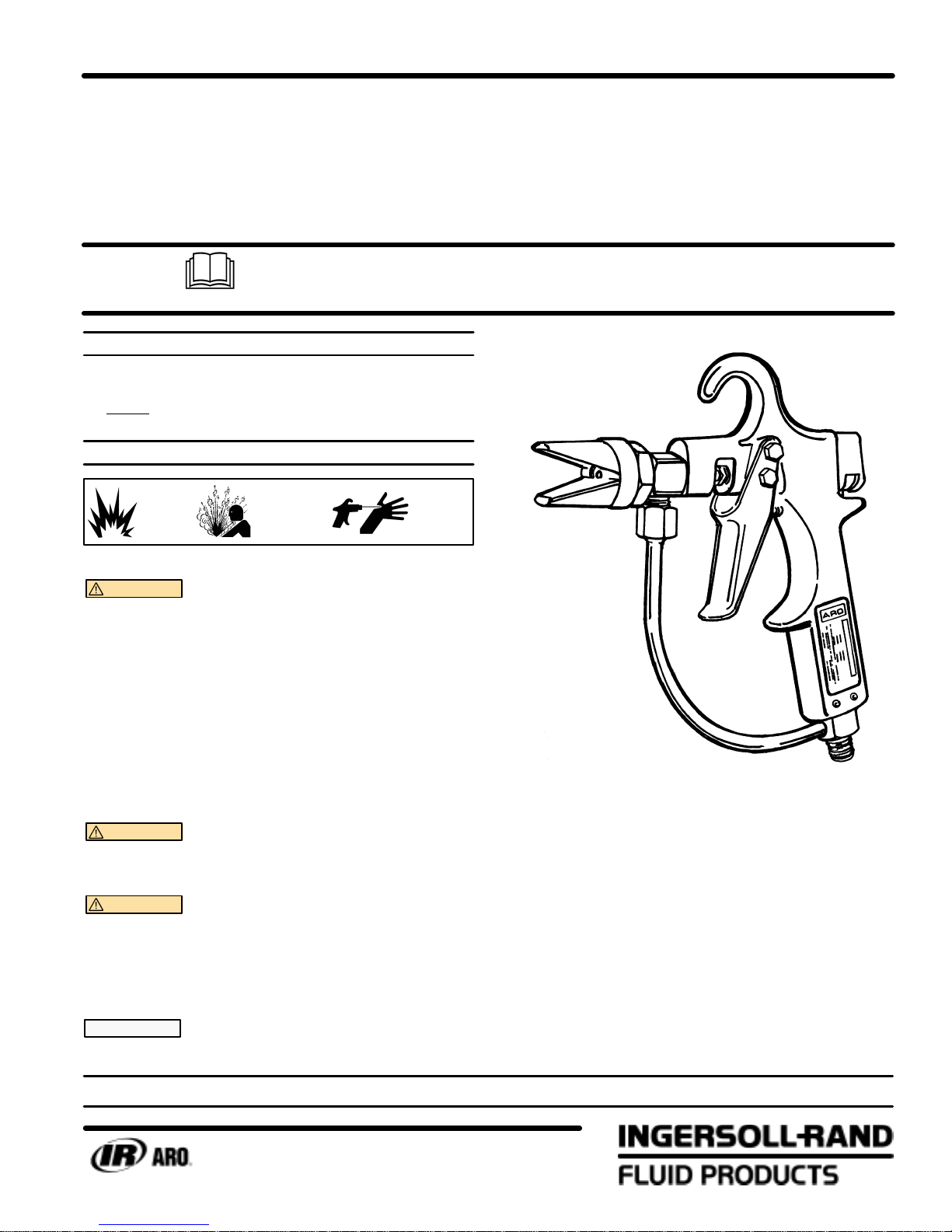
MAINTENANCE
W th proper care, th s un t w ll g ve long rel able serv ce. To ma nta n th s
performance t should be flushed out w th solvent mmed ately follow ng
each spray per od.
CAUTION Always disconnect pump power source and reĆ
lease all pressure before disassembly or removal of any part.
FOR CL ANING: Use solvent with highest possible flash point,
that is compatible to material being used.
1. ShutĆoff a r pressure to pump and rel eve l qu d pressure n system
through manual rel ef valve at outlet f lter on those models
equ pped, or tr gger gun mak ng sure pressure s rel eved. Never
attempt to force pa nt backward from gun through hose to pump
and pa nt conta ner.
2. Place gun safety lock n closed pos t on and remove spray t p from
gun. Place t p n small conta ner of solvent for soak ng and f nal
clean ng. Use soft br stle brush to remove any pa nt collect on on
t p. If t p or f ce s clogged, remove obstruct on by us ng a r blow gun
appl ed to outlet of or f ce at front of t p and blow ng back through
rear of t p, f obstruct on w ll not blow out, use clean ng w re, toothĆ
p ck or brush br stle to d slodge. N V R ATT MPT TO CL AN
TIP WHIL IT IS ATTACH D TO SPRAY GUN.
3. Remove gun from hose and clean exter or w th su table solvent and
brush. Allow gun to soak n solvent for a short t me f necessary to
soften accumulat on. After clean ng, w pe exter or of gun w th dry
cloth. (NOTE: Inter or of gun has not yet been cleaned).
4. Remove pump from pa nt conta ner and place pump nlet nto conĆ
ta ner of su table clean solvent.
5. D rect open end of hose nto pa nt conta ner and start pump by apĆ
ply ng only suff c ent a r pressure to cycle pump slowly and to force
pa nt from pump and hose nto grounded pa nt conta ner. When solĆ
vent beg ns to flow from hose, sw tch hose to grounded solvent conĆ
ta ner, ncrease a r pressure to pump allow ng solvent to c rculate
through pump, hose and back to conta ner for approx mately one
m nute or unt l exam nat on nd cates hose and system are clean.
6. Whenever 60530 nl ne sw vel f lter s be ng used, remove from
hose and gun, d sassemble and clean.
7. ShutĆoff a r pressure to pump and assemble gun to end of hose.
8. D rect end gun (w thout t p) nto top of grounded (bond ng recomĆ
mended) solvent conta ner and release safety lock on gun so tr gĆ
ger can be retracted.
9. Start pump w th gun tr gger retracted, ncrease a r pressure unt l
suff c ent pressure s obta ned to cause pump to cycle approx mateĆ
ly 25 cycles per m nute. Purge gun approx mately one m nute wh le
nterm ttently operat ng tr gger. Adjust pack ng gland f necessary to
prevent leakage.
10. ShutĆoff a r pressure to pump and pull gun tr gger to rel eve presĆ
sure n system wh le gun s st ll d rected nto grounded solvent conĆ
ta ner.
11. Place safety lock on gun n closed pos t on and reassemble cleaned
spray t p to gun, w pe all exter or surfaces clean.
12. D sconnect pump from power source.
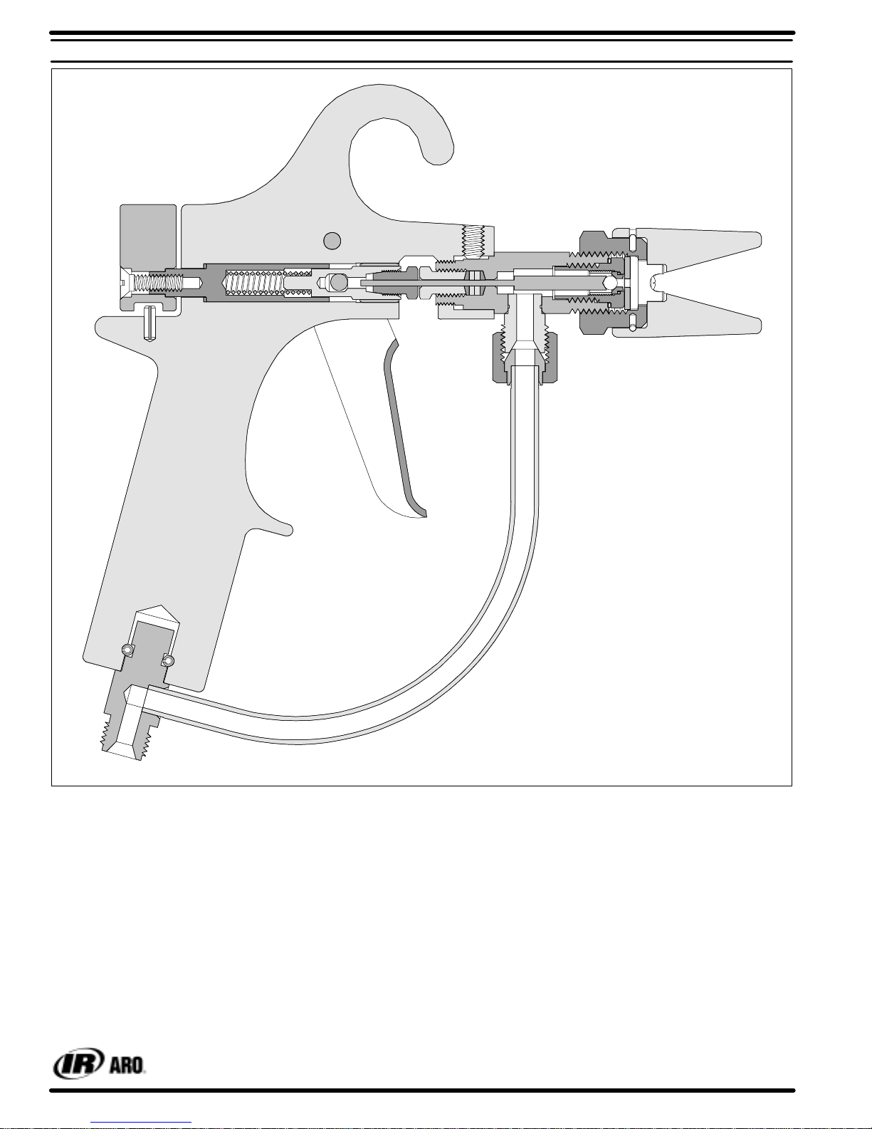
SERVICE
If mater al leakage occurs around the (12) reta n ng screw, the (10)
pack ng and the (11) flat pack ng have perhaps become worn. T ghten
the (12) reta n ng screw and f th s doesn't stop the leakage replace the
pack ng.
If mater al leakage occurs at the spray t p of the gun, check for d rt or
fore gn matter wh ch may prevent the (7) ball and stem assembly from
seat ng properly.
DISASSEMBLY
1. D sconnect a r l ne from pump and rel eve mater al l ne pressure by
pull ng (22) tr gger.
2. D sconnect mater al l ne from gun.
3. Unscrew the (1) cap and guard assembly and remove the (2) washĆ
er and spray t p.
4. Loosen the (13) collet nut.
5. Loosen the (19) set screw. D sconnect and remove the (21) nlet
tube braz ng assembly by loosen ng the tube nut and rotat ng the
tube assembly 90_to e ther s de of the (20) handle.
6. Unscrew the (9) spray gun body and adapter assembly from the
(20) handle.
7. Remove the (3) screw, (8) washer and (12) reta n ng screw from (9)
spray gun body and adapter assembly.
8. Remove the (7) ball and stem assembly and the (10) pack ng and
(11) flat pack ng from the (9) spray gun body and adapter assembly.
For normal cleaning or service, parts (14), (15), (16), (17), (18), (22),
(23), (24), (25), (26), (27) and (28) need not be removed.
REASSEMBLY
1. Insert the (7) ball and stem assembly nto the (9) spray gun body
and adapter assembly.
2. Carefully sl p the two (10) pack ngs and two (11) flat pack ngs n the
order shown n the d agram over the w re of the (7) ball and stem
assembly.
3. Sl de the (12) reta n ng screw onto the (7) ball and stem assembly
and push the pack ngs nto the (9) spray gun body and adapter asĆ
sembly. T ghten (12) reta n ng screw hand t ght.
4. Install the (8) washer on the (3) screw and screw the assembly nto
(9) spray gun body and adapter assembly hand t ght. Then back off
screw 3/4 turn.
5. Push the (7) ball and stem assembly forward unt l t seats on the ball
seat of the (3) screw and t ghten (12) reta n ng screw.
6. Screw the (9) spray gun body and adapter assembly nto the (20)
handle. Be sure the w re of the (7) ball and stem assembly enters
the hole n the (13) collet nut. Back off the (9) spray gun body and
adapter assembly unt l mater al nlet faces down. T ghten (19) set
screw.
7. Be ng sure the ball s st ll seated n the ball seat, ret ghten the (13)
collet nut.
8. T ghten the (3) screw.
9. Replace the (21) nlet tube braz ng assembly nto the (20) handle
and (9) spray gun body and adapter assembly.
10. Check safety operat on by rotat ng the (25) knob to the safe pos t on
and pull the (22) tr gger. If movement of the (7) ball and stem asĆ
sembly s noted, adjust the gun as follows. W th the safety off and
the ball seated on the ball seat, hold the tr gger and loosen the (13)
collet nut. Pull the tr gger back sl ghtly and ret ghten the (13) collet
nut. Recheck safety operat on and readjust f necessary.
11. Insert the spray t p and (2) washer n the (1) cap and guard assemĆ
bly and screw cap on (9) spray gun body and adapter assembly.