manuals.online logo
Brands
  1. Home
  2. •
  3. Brands
  4. •
  5. Ingersoll-Rand
  6. •
  7. Power Tools
  8. •
  9. Ingersoll-Rand 500A Series Setup guide

Ingersoll-Rand 500A Series Setup guide

47143300
Edition 1
September 2010
Save These Instructions
Air Impulse Wrench (Twin Blade )
Series 500A and 700A
Maintenance Information
2 47143300_ed1
WARNING
Always wear eye protection when operating or performing maintenance on this tool.
Always turn o the air supply and disconnect the air supply hose before installing, removing or adjusting any accessory on this tool or
before performing any maintenance on this tool.
Note: When reading the instructions, refer to exploded diagrams in Parts Information Manual when applicable (see under Related
Documentation for form numbers).
Changing The Mechanism Fluid
To change the Mechanism Fluid in the Impulse Mechanism,
proceed as follows:
1. Grasp the tool in Copper-covered or Leather- covered vise jaws
with the Angle Housing (69) Upward.
2. Using a Hex Wrench, remove the four Angle Housing Mounting
Screws (89) and Lock washer (90). Lift the assembled Angle
Housing o the Motor Housing (1). Remove the Housing Gasket
(78).
3. Lift the assembled mechanism o the Rotor (22).
4. Using a wrench, rotate theTorque Adjustment Screw (33
or 57) Clockwise untill the Screw stops. Rotate the Screw
Counterclockwise untill it stops or Makes six complete
revolutions.
5. Using a 2.5mm Hex wrench, unscrew and remove the Oil Plug
(59 or 63). Remove the Oil Plug Seal (60 or 64) and Oil Plug Seal
Support (61).
6. With the oil plug openings downward aver a container, rotate the
Drive Shaft (48) to purge the uid from the mechanism.
7. For Model 500A, thread theTee Wrench included with the
Tool Kit ( Part No. 180PQ-99) through the oil plug hole into the
Spring Guide (45) and Pull the Guide toward the output end of
the mechanism untill it stops.
For Model 700A, thread theTee Wrench included with the
Tool Kit ( Part No. 700PQ-99) through the oil plug hole into the
Spring Guide (45) that is 180° from the Torque Adjustment Screw
(57) and Pull the Guide toward the output end of the mechanism
untill it stops.
NOTICE
Do not substitute any other uid.
Failure to use the impulse mechanism uid provided could
damage the tool, increase maintenance and decrease
performance. Use only clean uid in these tools.
8. Using the syringe and uid from the uid Replacement Kit (Part
No. EQ106S-K400), ll the mechanism with the uid furnished
in the Kit untill the uid overows the ll hole. Model 500A will
require 9 cc of uid and Model 700A, 12 cc.
(Refer to Dwg. TPD1265)
(Dwg. TPD1265)
9. Submerge the ll opening in the remainder of the uid, and using
a wrench, rotate the Drive Shaft to purge any remaining air from
the system.
10. Remove the mechanism from the uid and use the Tee Wrench to
push the Spring Guide Assembly slowly downward untill the uid
ows from the ll opening.
11. Thread the Oil Plug with the Oil Plug Seal into the mechanism
until it is snug.
12. Using a 1.5 mm hex wrench, turn the Torque Adjustment Screw
clockwise until it stops. This is the maximum torque position.
13. Wipe the outside of the mechanism dry and clean and remove
the Oil Chamber Plug. Using the syringe, withdraw .2 cc of uid
from 500A models and .50 cc of uid from 700A models.
14. Install the Oil Chamber Plug and tighten it between
20 and 25 in–lb (2.3 and 2.8 Nm) torque.
15. Install the assembled mechanism on the rotor shaft.
16. Place the new Housing Gasket on the Angle Housing and install
the assembled Angle Housing over the Drive Shaft against the
Housing. Install the four Angle Housing Mounting Screw and
Lock Washers.Tighten each Screws between 45 and 50 in-lb (5.1
and 5.6 Nm) torque.
47143300_ed1 3
Disassembly
General Instructions
1. Do not disassemble the tool any further than necessary to replace
or repair damaged parts.
2. When grasping a tool or part in a vise, always use leather–covered
or copper–covered vise jaws to protect the surface of the part
and help prevent distortion. This is particularly true of threaded
members and housings.
3. Do not remove any part which is a press t in or on an assembly
unless the removal of that part is necessary for repairs or
replacement.
Disassembly of the Angle Head
1. Grasp the tool in the copper-covered or leather-covered vise jaws
with the Angle Housing (69) upward.
2. Using a hex wrench, remove the four Angle Housing Mounting
Screw (89) and Lock washer (90). Lift the assembled Angle
Housing o the Motor Housing (1). Remove the Housing Gasket
(78) and Angle Housing Spacer (72).
3. Unscrew and remove the Bearing Cap Retainer Screw (74).
4. Using the spanner wrench, unscrew and remove the Pinion
Bearing Cap (73).
5. Pull the two Pinion Bearings (75), any Pinion Bearing Shims (76)
and Bevel Pinion (77) out of the Angle Housing.
6. Unscrew and remove the Spindle Cap Retaining Screw (86).
7. Unscrew and remove the Spindle Cap (85) and pull the Spindle
(81), Spindle Shaft (79) and any Spindle Shims (80 or 84) that are
in the assembly.
Disassembly of the Impulse Mechanism
1. Lift the assembled mechanism o the Rotor (22).
2. Using a wrench, rotate theTorque Adjustment Screw (33
or 57) clockwise untill the Screw stops. Rotate the Screw
counterclockwise untill it stops or makes six complete
revolutions.
3. Using a 2.5 mm hex wrench, unscrew and remove the
Oil Plug (59 or 63). Remove the Oil Plug Seal (60 or 64) and
Oil Plug Seal Support (61).
4. With the oil plug opening downward over a container, rotate the
Drive Shaft (48) to purge teh uid from the mechanism.
5. Grasp the ats of the Housing (31 or 32) in vise jaws with the
output end of the Drive Shaft downward.
6. Insert the pins of the spanner plug from the No. 180PQ–99 or No.
700A-99 Tool Kit into the two holes in the Housing Cap (35). Using
a wrench on the plug, unscrew and remove the Housing Cap
from the Housing Assembly.
Refer to Dwg. TPD1295.
Spanner
Plug
Counterclockwise
to Loosen
(Dwg. TPD1295)
7. Stand the disassembly arbor from the Tool Kit, large end
downward, on a workbench or the table of an arbor press. Insert
the output end of the Drive Shaft into the central opening and
either tap the Housing downward o the components or use the
pressing sleeve in the Kit to press the Housing downward o the
components.
Refer to Dwg. TPD1296.
Pressing
Sleeve
Housing
Tap edge lightly with
brass hammer or use
pressing sleeve from
tool kit
Disassembly Arbor
from tool kit
(Dwg. TPD1296)
8. Disassemble the components of the mechanism in the sequence
shown in Drawing TPB960.
Disassembly of the Motor
1. Grasp the Motor Housing (1) in vise jaws with the shaft of the
Rotor (22) upward.
2. Insert the pins of the end plate spacer spanner into the holes in
the Front End Plate Spacer (27). Using a wrench, unscrew and
remove the Spacer. This is a left–hand thread; rotate the wrench
clockwise to remove the Spacer.
Refer to Dwg. TPD1297.
End Plate
Spacer Sapnner Clockwise to Loosen
(Dwg. TPD1297)
3. Pull the assembled motor from the Motor Housing.
4. Remove the Front End Plate (24), Front Rotor Bearing (26),
Cylinder Assembly (20) andVanes (23) from the Rotor.
5. On the table of an arbor press, support the Rear End Plate (18)
with blocks as close to the Rotor as possible and press the Rotor
out of the Rear End Plate and Rear Rotor Bearing (19).
NOTICE
Do not enlarge or damage the shaft hole in the End Plate.
6. To remove the Rear Rotor Bearing from the Rear End Plate, use a
small drift or pin punch through the central opening of the Rear
End Plate to tap the Bearing out of the End Plate.
Refer to Dwg. TPD1299.
4 47143300_ed1
General Instructions
1. When grasping a tool or part in a vise, always use leather–covered
or copper–covered vise jaws to protect the surface of the part
and help prevent distortion. This is particularly true of threaded
members and housings.
2. Always press on the inner ring of a ball–type bearing when
installing the bearing on a shaft.
3. Always press on the outer ring of a ball–type bearing when
pressing the bearing into a bearing recess.
4. Except for bearings and mechanism parts, always clean every part
and wipe every part with a thin lm of oil before installation.
5. Wipe a thin lm of mechanism uid on all internal mechanism
components before installing them in the mechanism.
6. Apply a lm of O–ring lubricant to every O–ring before
installation.
Assembly of the Motor
1. If the Reverse Valve Bushing (7) was removed from the Motor
Housing (1), press it into the Housing, lug end trailing, from the
side of the Housing opposite the lever position. Make certain the
ports align with the bushing holes.
2. Thread the Inlet Bushing (14) into the threaded hole at the rear of
the handle of the Motor Housing and tighten it between 30 and
35 ft-lb (40 and 47 Nm) torque.
3. Position the Exhaust Deector Assembly (15) in the hole at
the rear of the motor housing handle and install the Deector
Retaining Pin (16) to secure it in position.
NOTICE
It may be necessary to slide the Assembly in or out in order to
align the groove in the Assembly with the pin hole.
4. Install two new Reverse Valve Bushing Seals (8) in the grooves
inside the Reverse Valve Bushing, if they were removed.
5. Install the Reverse Valve Seal (6) in the groove next to the large
hub of the Reverse Valve (5).
6. Install the Reverse Valve Assembly, seal and trailing, into the lever
side of the Motor Housing. Make certain the square depression
on the shaft of the Valve faces forward toward the output end of
the tool.
7. Install the Reverse Lever Seal (3) in the groove on the small hub of
the Reverse Lever (2).
8. Insert the Throttle Ball (12) followed by the Throttle Valve Spring
(11) into the Reverse Valve Assembly.
9. Position the Reverse Lever Assembly on the Reverse Valve
Assembly with the indicator lever rearward. Make certain the
crossholes in the Lever align with the pin holes in theValve. Press
the Knob Retaining pin (4) into the Lever and Valve.
10. Insert the Throttle Plunger (13) into the Reverse Valve Assembly.
11. Position the Throttle Lever (9) on the Motor Housing and secure it
by pressing the Throttle Lever Pin (10) into the Housing and Lever.
12. Using an arbor pres and a piece of tubing that contacts the outer
ring of the bearings, press the Front Rotor Bearing (26) into the
Front End Plate (24) and the Rear Rotor Bearing (19) into the Rear
End Plate (18). (Refer to Dwg.TPD1300).
Bearing
Tubing
End Plate
(Dwg. TPD1300)
13. Stand the Rotor (22) on the table of an arbor press. It should be
upright on a at metal plate having a clearance hole for the shaft.
The shaft with the hex must be upward.
14. Place a 0.001” (0.025mm) shim on the upward surface of the large
portion of the rotor body. Using a piece of tubing that contacts
the inner ring of the bearing, press the Front Rotor Bearing and
Front End Plate, End Plate leading, onto the shaft of the Rotor
until the End Plate contacts the shim. Remove the shim. (Refer to
Dwg. TPD1301).
Pressign Plug
Front Rotor
Bearing
Rotor
Plate with Rotor
Shaft clearance
Front End Plate
0.001”(0.025 mml
Shim space
(Dwg. TPD1301)
(Dwg. TPD1299)
7. Press the Reverse Lever Pin (4) out of the Reverse Lever (2) and
remove the Reverse Lever, Reverse Lever Seal (3),Throttle Valve
Spring (11) and the Throttle Ball (12).
8. Spread the end of the Suspension Bail (17), where the ends enter
the Motor Housing, and remove the Bail.
9. Using a pin punch, tap the Throttle Lever Pin (10) and the
Deector Retaining Pin (16) out of the Handle. Remove the
Throttle Lever (9),Throttle Plunger (13) and the Exhaust Deector
Assembly (15).
10. Push the Reverse Valve Assembly (5) out the throttle lever end of
the Housing and Remove the two ReverseValve Bushing Seals (8)
if they need to be replaced.
11. Unscrew and remove the Inlet Bushing (14).
12. If the ReverseValve bushing (7) must be replaced, press it from
the Motor Housing.
Assembly
47143300_ed1 5
15. Coat each Vane (23) with a thin lm of oil and insert a Vane
into each of the rotor vane slots with the straight edge ofVane
outward.
16. Install the Cylinder (20) over the Vanes and Rotor. Make certain
the contour at the end of the Cylinder matches the contour of the
End Plate. Make certain the Cylinder Alignment Pin (21) enters the
hole in the face of the End Plate.
17. Place the Rear End Plate and Bearing against the face of the
Cylinder, Bearing end trailing. Make certain the Cylinder
Alignment Pin enters the hole in the End Plate.
18. Insert the assembly, Rear End Plate leading, into the Motor
Housing making sure the End Plate Alignment Pin (25) enters the
notch in the Housing.
It may be necessary to tap the assembly into position with a brass
of plastic hammer. (Refer to Dwg.TPD1303).
(Dwg. TPD1303)
19. Grasp the Motor Housing in vise jaws with the rotor shaft upward.
Thread the Front End Plate Spacer (27) into the Housing and
using the end plate spacer spanner, tighten the Spacer to 12 ft-lb
(16 Nm) torque. This is a left-hand thread; rotate the wrench
counterclockwise to tighten. (Refer to Dwg. TPD1304).
Counterclockwise
to Tighten
Spanner
(Dwg. TPD1304)
20. After installing the Front End Plate Spacer, grasp the shaft of the
Rotor and rotate it by hand. If the Rotor does not turn easily,
disassemble the motor unit and determine where the assembly is
binding. The motor must rotate freely before proceeding further
with the assembly.
Assembly of the Impulse Mechanism
1. Insert the long shaft of the Spring Guide (41) into the central
opening of the O-ring Installer furnished with the Tool Kit (Part
No. 180PQ-99 or Part No. 700A-99). Place the Spring Guide Seal
(46) on the tapered end of the installer and roll the Seal up the
taper and into the groove on the large body of Spring Guide.
For Model 700A, repeat the procedure with the second Spring
Guide and Seal. (Refer to Dwg.TPD 1305)
Spring Guide Seal
O-Ring Installer
(Dwg. TPD1305)
2. For Model 500A, insert the Relief Valve (44), large end trailing,
into the Liner (42). Insert the assembled Spring Guide, long hub
with annular groove leading, into the Liner against the Relief
Valve. (Refer to Dwg. TPD1306).
Relief Valve
Liner
Long end of Spring Guide
with groove.
(Dwg. TPD1306)
For Model 700A, when looking inside the central opening of the
Linder (42), the internal wall has three holes on one side which do
not extend through the wall. The opening on the end face of that
wall is for the Relief Valve (44). Install the Relief Valve, large end
trailing, into that opening. Insert the Guide Assist Spring (47) into
the hole in the end face of the opposite wall.
3. For Model 700A, insert a Spring Guide Assembly, large end
trailing, into the opening against the Relief Valve. Mark this
opening with a felt marker to indicate that it contains the Relief
Valve. Install the remaining Spring Guide Assembly, large end
trailing, into the hole with the Spring.
4. For Model 500A, install the Liner Cover O-ring (40) in the groove
around the Rear Liner Cover (39).
For Model 700A, install the Rear Liner Cover Seal (41) in the
annular groove on the face of the Rear Liner Cover (39).
5. For Model 700A, install the two Front Liner Cover Guide Seals
(62) in the openings on the face of the Front Liner Cover (56).
6. For Model 500A, if the Oil Stop Cap Assembly (65) was removed
from the Front Liner Cover (54), install the Stop Cap O-ring (66)
and Back-up Ring (67) in the groove of the Cap and insert the
Assembly into the Cover. (Refer to Dwg. TPD1311).
Back-up Ring
Stop Cap O-ring
Oil Stop Cap
Front Liner Cover
(Dwg. TPD1311)
7. Insert the short round hub of the Drive Shaft (61) into the central
opening of the Rear Linder Cover.
8. For Model 500A, insert a Blade (49) into one slot in the Drive
Shaft with the Blade Assembly Pin (50) inward toward the Shaft.
Install the Blade Springs (51) through the Drive Shaft and encircle
the Pins in the Blade. Place the remaining Blade on the Springs
making certain the Springs encircle the Pins in that Blade.
For Model 700A, insert a Blade (49) into one slot in the Drive
Shaft. Install the Blade Springs (65) through the Drive Shaft and
into the holes in the Blade. Place the remaining Blade on the
Springs making certain the springs enter the holes in that Blade.
6 47143300_ed1
NOTICE
This following installation can be accomplished more easily by
aligning the compressed Blades with the webs at the narrowest
portion of the opening. Keeping the Blades on the web allows
them to slide the length of the Liner without interference.
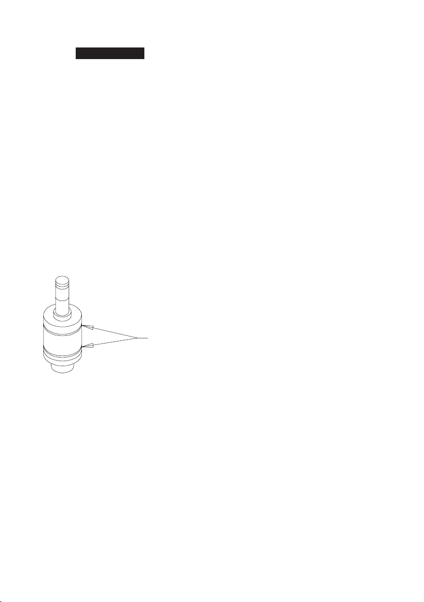
9. Using nger pressure, compress the Springs with the Blades
until the outer edges of the Blades are ush with the drive shaft
surface. Capture the Blades in this position by installing the Liner
Assembly, guide spring end trailing, over the Drive Shaft and
against the Rear Liner Cover. Make certain the Liner Pins (43) in
the Liner enter the holes in the Cover.
10. Insert the hub end of the Rear Liner Cover into the Disassembly
Arbor from the Tool Kit and stand it on a workbench with the
Drive Shaft upward.
11. Install the Seal Back-Up Ring (53) followed by the Drive Shaft
O-ring (52) in the central opening in the face of the Front liner
Cover.
12. Install the Front Liner Cover Assembly over the Drive Shaft and
against the Liner.
For Model 500A, make certain the Oil Stop Cap Assembly aligns
with the Spring Guide assembly.
For Model 700A, make certain the Torque Adjustment Screw (57)
aligns with the proper spring guide opening that was marked
during assembly.
13. For Model 500A, install the Liner Cover O-ring (41) in the groove
that was formed where the Rear Liner Cover contacts the Liner
and install the Liner O-ring (37) in the groove formed where the
Front Liner Cover contacts the Liner. Lubricate the Seals with
O-ring lubricant. (Refer to Dwg. TPD1312).
Liner Seals
(Dwg. TPD1312)
14. For Model 500A, apply some grease to the Liner Cover Seal (68)
and install it in the grooves inside the Liner Housing (32) near the
end with the external wrench ats.
For Model 700A, apply some grease to the two Liner Cover Seals
(68) and install them in the grooves inside the Liner Housing (31)
near the end with the external wrench ats.
15. For Model 500A, orient the Liner Housing so the Liner Cover Pin
(55) will enter the hole in the Housing and install the Housing
over the Liner.
For Model 700A, place the Liner Housing Seal end trailing, over
the assembled Liner. Make certain the notch in the trailing end
face of the Housing aligns with the Oil Plug (59) in the Front Liner
Cover. Use the Pressing Sleeve from theTool Kit to oppress the
Housing over the Seals during installation.
16. Grasp the ats of the Liner Housing in the vise jaws with the
output spindle downward. Remove the Rear Liner Cover and ll
the recess in the Cover with grease. Reinstall the Cover and push
it downward below the threads at the rear of the Housing.
17. Using Spanner Plug furnished with the Tool Kit and a torque
wrench, install the Housing Cap, (castellated end leading for
Model 700A). Tighten the Cap between 101 and 116 ft-lb (137
and 157 Nm) torque.
18. Make certain the Drive Shaft rotates freely and then ll the
mechanism with uid as instructed in the section, CHANGING
THE MEVHANISM FLUID.
Assembly of the Angle Head
1. If the Spindle Shaft Busing was removed, press a new Bushing
into the Angle Housing (69), large end trailing, until it seats.
2. Lubricate and install the two pinion Bearings (75) on the shaft of
the Bevel Pinion (77) and insert the assembly, gear end leading,
into the motor end of the Angle Housing.
3. Install the Pinion Bearing Cap (73) and tighten it snug.
4. Insert the Spindle Shaft (79) into the gear end of the Spindle (81).
5. Chalk the gear teeth of the Spindle and carefully insert the
assembly into the Angle Housing. Make certain the Shaft enters
the Bushing. Install the Spindle Cap (85) and lightly tighten it.
6. Using a wrench on the square drive, rotate the Spindle to
suciently mark the chalked gear teeth. Carefully remove the
Spindle Cap and examine the gear teeth.
7. If the gearing runs smoothly and gear tooth engagement is
good, reinstall the Cap and tighten it and the Pinion Bearing Cap
securely.
If the gearing does not run smoothly or gear tooth engagement
is poor, proceed as follows:
Determine which way the Spindle or Pinion must move to
improve engagement.
Insert the correct thickness Pinion Bearing Shim (76), Spindle
Upper Shim (80) or Spindle Lower Shim (84) separately or in
combination to achieve the desired engagement.
Chalk the gear teeth and test the tooth engagement again.
When satised that the proper bevel gear engagement has
been achieved, tighten the Spindle Cap and Pinion Bearing
Cap securely.
8. Remove the Grease Plug (71) and ll the cavity with gear grease.
9. Install the Bearing Cap Retaining Screw (74) and Spindle Cap
Retaining Screw (86) and tighten them securely.
10. Install the assembled Impulse Unit Drive Assembly on the rotor
shaft in the Motor Housing (1).
11. Install the Angle Housing Space (72), small opening leading, into
the Drive Shaft (48) against the impulse mechanism.
12. Place a new Gasket (78) on the Angle Housing and install the
assembled Angle Housing over the Drive Shaft against the
Housing. Install the four Angle Housing Mounting Screws (89)
and Lock Washers (90). Tighten each Screw between 45 and 50
in-lb (5.1 and 5.6 Nm) torque.
a.
b.
c.
d.
47143300_ed1 7
Related Documentation
For additional information refer to:
Product Safety Information Manual 04584983.
Product Information Manual 47133053.
Parts Information Manual 47143292.
Manuals can be downloaded from www.ingersollrandproducts.com
www.ingersollrandproducts.com
© 2010 Ingersoll Rand

This manual suits for next models

1

Other Ingersoll-Rand Power Tools manuals

Ingersoll-Rand W5001 Series User manual

Ingersoll-Rand

Ingersoll-Rand W5001 Series User manual

Ingersoll-Rand 2925 Series User manual

Ingersoll-Rand

Ingersoll-Rand 2925 Series User manual

Ingersoll-Rand IR30BV Installation guide

Ingersoll-Rand

Ingersoll-Rand IR30BV Installation guide

Ingersoll-Rand 103A User manual

Ingersoll-Rand

Ingersoll-Rand 103A User manual

Ingersoll-Rand DEP Series User manual

Ingersoll-Rand

Ingersoll-Rand DEP Series User manual

Ingersoll-Rand QM Series User manual

Ingersoll-Rand

Ingersoll-Rand QM Series User manual

Ingersoll-Rand R1000 Series User manual

Ingersoll-Rand

Ingersoll-Rand R1000 Series User manual

Ingersoll-Rand IR25BV User manual

Ingersoll-Rand

Ingersoll-Rand IR25BV User manual

Ingersoll-Rand IR30VRD User manual

Ingersoll-Rand

Ingersoll-Rand IR30VRD User manual

Ingersoll-Rand 280PQ1 User manual

Ingersoll-Rand

Ingersoll-Rand 280PQ1 User manual

Ingersoll-Rand 170 User manual

Ingersoll-Rand

Ingersoll-Rand 170 User manual

Ingersoll-Rand PROMAXX MX60-SD User manual

Ingersoll-Rand

Ingersoll-Rand PROMAXX MX60-SD User manual

Ingersoll-Rand LA158 User manual

Ingersoll-Rand

Ingersoll-Rand LA158 User manual

Ingersoll-Rand 9RS-EU Series User manual

Ingersoll-Rand

Ingersoll-Rand 9RS-EU Series User manual

Ingersoll-Rand 1701 Series User manual

Ingersoll-Rand

Ingersoll-Rand 1701 Series User manual

Ingersoll-Rand 2146 Series User manual

Ingersoll-Rand

Ingersoll-Rand 2146 Series User manual

Ingersoll-Rand EL 24V Series Setup guide

Ingersoll-Rand

Ingersoll-Rand EL 24V Series Setup guide

Ingersoll-Rand PowerForce PF700 User manual

Ingersoll-Rand

Ingersoll-Rand PowerForce PF700 User manual

Ingersoll-Rand 1215Ti User manual

Ingersoll-Rand

Ingersoll-Rand 1215Ti User manual

Ingersoll-Rand AIR RATCHET WRENCH 1111 User manual

Ingersoll-Rand

Ingersoll-Rand AIR RATCHET WRENCH 1111 User manual

Ingersoll-Rand 130A1M Setup guide

Ingersoll-Rand

Ingersoll-Rand 130A1M Setup guide

Ingersoll-Rand R3130 User manual

Ingersoll-Rand

Ingersoll-Rand R3130 User manual

Ingersoll-Rand 40PSQ1 User manual

Ingersoll-Rand

Ingersoll-Rand 40PSQ1 User manual

Ingersoll-Rand PowerForce PF705 User manual

Ingersoll-Rand

Ingersoll-Rand PowerForce PF705 User manual

Popular Power Tools manuals by other brands

Floor iQ VLFR-220R user guide

Floor iQ

Floor iQ VLFR-220R user guide

Stanley 0753 MKII Instruction and service manual

Stanley

Stanley 0753 MKII Instruction and service manual

Makita 3901 instruction manual

Makita

Makita 3901 instruction manual

Makita DTS131 instruction manual

Makita

Makita DTS131 instruction manual

Makita HG5030 instruction manual

Makita

Makita HG5030 instruction manual

Kitagawa TT200BE-01 instruction manual

Kitagawa

Kitagawa TT200BE-01 instruction manual

Atlas Copco ETC STR21-28-12-LI5 Instruction supplement

Atlas Copco

Atlas Copco ETC STR21-28-12-LI5 Instruction supplement

Alpha tools AT-OF 1200 E Original operating instructions

Alpha tools

Alpha tools AT-OF 1200 E Original operating instructions

Von Arx FR 200 operating manual

Von Arx

Von Arx FR 200 operating manual

Festool OFK 500 Q Operating instructions/spare parts list

Festool

Festool OFK 500 Q Operating instructions/spare parts list

Makita HM1140C instruction manual

Makita

Makita HM1140C instruction manual

Craftsman 71.74291 Operator's manual

Craftsman

Craftsman 71.74291 Operator's manual

Alemite 585-A1 Service guide

Alemite

Alemite 585-A1 Service guide

Meec 023-024 instruction manual

Meec

Meec 023-024 instruction manual

Rothenberger ROMAX 3000 AC Instructions for use

Rothenberger

Rothenberger ROMAX 3000 AC Instructions for use

Makita 3600H instruction manual

Makita

Makita 3600H instruction manual

Makita Makstar BSS610 instruction manual

Makita

Makita Makstar BSS610 instruction manual

Ryobi JS550LK Manuel d'utilisation

Ryobi

Ryobi JS550LK Manuel d'utilisation

manuals.online logo
manuals.online logoBrands
  • About & Mission
  • Contact us
  • Privacy Policy
  • Terms and Conditions

Copyright 2025 Manuals.Online. All Rights Reserved.