manuals.online logo
Brands
  1. Home
  2. •
  3. Brands
  4. •
  5. Ingersoll-Rand
  6. •
  7. Power Tools
  8. •
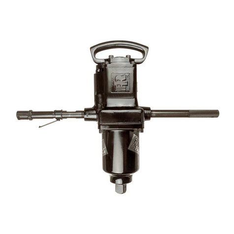
  9. Ingersoll-Rand 93 Series Setup guide

Ingersoll-Rand 93 Series Setup guide

This manual suits for next models

11

Other Ingersoll-Rand Power Tools manuals

Ingersoll-Rand W1000 Series User manual

Ingersoll-Rand

Ingersoll-Rand W1000 Series User manual

Ingersoll-Rand 104 A User manual

Ingersoll-Rand

Ingersoll-Rand 104 A User manual

Ingersoll-Rand AIR HAMMER 114G User manual

Ingersoll-Rand

Ingersoll-Rand AIR HAMMER 114G User manual

Ingersoll-Rand QE4 Series Setup guide

Ingersoll-Rand

Ingersoll-Rand QE4 Series Setup guide

Ingersoll-Rand 327 Series User manual

Ingersoll-Rand

Ingersoll-Rand 327 Series User manual

Ingersoll-Rand 341 Setup guide

Ingersoll-Rand

Ingersoll-Rand 341 Setup guide

Ingersoll-Rand 325B User manual

Ingersoll-Rand

Ingersoll-Rand 325B User manual

Ingersoll-Rand DB9-EU Series User manual

Ingersoll-Rand

Ingersoll-Rand DB9-EU Series User manual

Ingersoll-Rand 341 User manual

Ingersoll-Rand

Ingersoll-Rand 341 User manual

Ingersoll-Rand 170PG Series User manual

Ingersoll-Rand

Ingersoll-Rand 170PG Series User manual

Ingersoll-Rand R1000 Series User manual

Ingersoll-Rand

Ingersoll-Rand R1000 Series User manual

Ingersoll-Rand QM Series User manual

Ingersoll-Rand

Ingersoll-Rand QM Series User manual

Ingersoll-Rand 1103 User manual

Ingersoll-Rand

Ingersoll-Rand 1103 User manual

Ingersoll-Rand IR30BV Installation guide

Ingersoll-Rand

Ingersoll-Rand IR30BV Installation guide

Ingersoll-Rand 45P3 User manual

Ingersoll-Rand

Ingersoll-Rand 45P3 User manual

Ingersoll-Rand AIR RATCHET WRENCH 1111 User manual

Ingersoll-Rand

Ingersoll-Rand AIR RATCHET WRENCH 1111 User manual

Ingersoll-Rand LA158 User manual

Ingersoll-Rand

Ingersoll-Rand LA158 User manual

Ingersoll-Rand 100PQ1 User manual

Ingersoll-Rand

Ingersoll-Rand 100PQ1 User manual

Ingersoll-Rand W5133P-C1D1 User manual

Ingersoll-Rand

Ingersoll-Rand W5133P-C1D1 User manual

Ingersoll-Rand MX60 User manual

Ingersoll-Rand

Ingersoll-Rand MX60 User manual

Ingersoll-Rand ARO 7165-B-EU Configuration guide

Ingersoll-Rand

Ingersoll-Rand ARO 7165-B-EU Configuration guide

Ingersoll-Rand 46PQ1 User manual

Ingersoll-Rand

Ingersoll-Rand 46PQ1 User manual

Ingersoll-Rand 2915P1 User manual

Ingersoll-Rand

Ingersoll-Rand 2915P1 User manual

Ingersoll-Rand W5300 Series User manual

Ingersoll-Rand

Ingersoll-Rand W5300 Series User manual

Popular Power Tools manuals by other brands

ISLAND HOPPER Power Egg HT-309 operating instructions

ISLAND HOPPER

ISLAND HOPPER Power Egg HT-309 operating instructions

Sioux Tools SSR6P25 Instructions-parts list

Sioux Tools

Sioux Tools SSR6P25 Instructions-parts list

Makita HM1317C technical information

Makita

Makita HM1317C technical information

ABB Smart Tool + quick start guide

ABB

ABB Smart Tool + quick start guide

Baumr-AG BMJK-24S user manual

Baumr-AG

Baumr-AG BMJK-24S user manual

Bosch Professional GST 18 V-LI S Original instructions

Bosch

Bosch Professional GST 18 V-LI S Original instructions

Ronix RA-2702 quick start guide

Ronix

Ronix RA-2702 quick start guide

Nordson ProBlue user guide

Nordson

Nordson ProBlue user guide

aoyue int6028 instruction manual

aoyue

aoyue int6028 instruction manual

Hitachi CJ 65VA2 Instruction manual and safety instructions

Hitachi

Hitachi CJ 65VA2 Instruction manual and safety instructions

Makita HM1304 instruction manual

Makita

Makita HM1304 instruction manual

Kurtz Ersa Ersa X-TOOL VARIO operating instructions

Kurtz Ersa

Kurtz Ersa Ersa X-TOOL VARIO operating instructions

SCHUNK KSO 65 Installation and operating instruction

SCHUNK

SCHUNK KSO 65 Installation and operating instruction

Harken LokHead 500 user manual

Harken

Harken LokHead 500 user manual

Senco DuraSpin ExTPro installation instructions

Senco

Senco DuraSpin ExTPro installation instructions

Ferm JSM1020 Original instructions

Ferm

Ferm JSM1020 Original instructions

Milwaukee M12 FUEL 2559-20 Operator's manual

Milwaukee

Milwaukee M12 FUEL 2559-20 Operator's manual

EINHELL BT-CD 12/2 operating instructions

EINHELL

EINHELL BT-CD 12/2 operating instructions

manuals.online logo
manuals.online logoBrands
  • About & Mission
  • Contact us
  • Privacy Policy
  • Terms and Conditions

Copyright 2025 Manuals.Online. All Rights Reserved.

16574212
Edition 2
May 2014
Save These Instructions
Air Percussive Digger
93 and 95 Series
Maintenance Information
2 16574212_ed2
Product Safety Information
WARNING
Failure to observe the following warnings, and to avoid these potentially hazardous situations, could result in death or serious
injury.
Read and understand this and all other supplied manuals before installing, operating, repairing, maintaining, changing accessories
on, or working near this product.
Always wear eye protection when operating or performing maintenance on this tool. The grade of protection required should be
assessed for each use and may include impact-resistant glasses with side shields, goggles, or a full face shield over those glasses.
Always turn o the air supply, bleed the air pressure and disconnect the air supply hose when not in use, before installing, removing
or adjusting any accessory on this tool, or before performing any maintenance on this tool or any accessory.
Note: When reading the instructions, refer to exploded diagrams in parts Information Manuals when applicable (see under Related Documentation
for form numbers).
Lubrication
•
•
•
•
Each time the 93 and 95 Series Diggers are disassembled
for maintenance, repair or replacement of parts, lubricate
the tool as follows:
Inject approximately 3 cc of oil into the air inlet of
the Grip Handle Digger before attaching the air hose.
Disassembly
General Instructions
Do not disassemble the tool any further than necessary to replace
or repair damaged parts.
Whenever grasping a tool or part in a vise, always use leather-
covered or copper-covered vise jaws to protect the surface of
the part and help prevent distortion. This is particularly true of
threaded members and housings.
Do not remove any part which is a press t in or on a subassembly
unless the removal of that part is necessary for repairs or replace-
ment.
Do not disassemble the tool unless you have a complete set of
new gaskets and O-rings for replacement.
Disassembly of the Digger
Clamp the Barrel (33) of the Digger in leather-covered or copper-
covered vise jaws with the Handle (1, 31) upward.
Remove the Handle Bolt (25), Handle Bolt Lock Washer (26), and
the Handle Bolt Nut (27).
Carefully remove the Handle and the Valve Box (28).
After removing the Barrel from the vise, tip it to allow the
Piston (32) to slide out.
Regrasp the Barrel in the vise, accessory end upward.
Remove the Sleeve Locking Spring (36).
Loosen the Retaining Sleeve (37).
1.
2.
3.
4.
1.
2.
3.
4.
5.
6.
7.
Remove the Retaining Sleeve and the Accessory (41) along with
the Buer Spacer (39), Buer Washer (40), and the Buer (38).
If required, drive the Nozzle (35) and/or the Barrel Bushing (34)
from the Barrel Assembly (33).
If required, remove the Spacer, Washer, and Buer from the
Sleeve.
Disassembly of the Handle Assembly
Clamp the Handle Assembly in leather-covered or copper-covered
vise jaws with the Valve Box (28) upward.
Carefully remove the Valve Box, Valve Box Dowel (30), Valve (31),
and the Valve Dowel (29).
Drive the Throttle Lever Pin (11) from the Handle and remove the
Throttle Lever (10).
Remove the Throttle Valve Cap (3) and the Throttle Valve
Spring (2).
From the throttle lever end, push the Throttle Valve (5), Throttle
Valve Bushing (12), and the Throttle Valve Plunger (13) from the
Handle.
If required, remove the Throttle Valve Face Cap Nut (6), the
Throttle Valve Face Cap (7), the Throttle Valve Face (8), and the
Throttle Valve Face Lock Washer (9) from the Throttle Valve.
Unscrew the Inlet Bushing (4).
8.
9.
10.
1.
2.
3.
4.
5.
6.
7.
Assembly
General Instructions
Whenever grasping a tool or part in a vise, always use leather-
covered or copper-covered vise jaws. Take extra care with
threaded parts and housings.
Always clean every part and wipe every part with a thin lm of oil
before installation.
Apply a lm of O-ring lubricant to all O-rings before nal
assembly.
Assembly of the Handle Assembly
Clamp the Inside Trigger Handle Assembly (1) in leather-covered
or copper-covered vise jaws with the inlet valve bore upward.
Place the Throttle Valve Face Lock Washer (9) on the threaded end
of the Throttle Valve (5).
Follow the Lock Washer with the Throttle Valve Face (8) and Throt-
tle Valve Face Cap (7).
Secure the assembly with the Throttle Valve Face Cap Nut (6).
Place the Throttle Valve, long end rst, into the Handle.
Follow the Throttle Valve with the Throttle Valve Spring (2) and
secure with the Throttle Valve Cap (3).
1.
2.
3.
1.
2.
3.
4.
5.
6.
Install the Inlet Bushing (4).
Rotate the Handle in the vise to allow installation of the Throttle
Lever (10).
Install the Throttle Valve Plunger (13) into the throttle valve bore.
From the inside of the Handle, install the Throttle Lever.
Secure the Throttle Lever with the Throttle Lever Pin (11) making
sure that the Lever actuates the Throttle Valve.
Assembly of the Digger
If required, press the Barrel Bushing (34) and/or the Nozzle (35)
into the Barrel Assembly (33).
Place the Piston (32), long end rst, into the Barrel.
Clamp the Handle Assembly (1, 31) in leather-covered or copper-
covered vise jaws with the top downward.
Carefully place the Valve Box Dowel (30) into the dowel hole in
the handle.
Place the Valve (31) and the Valve Dowels (29) into the Valve
Box (28).
Place the assembled Valve Box onto the handle, aligning the Valve
Box Dowel with the dowel hole.
7.
8.
9.
10.
11.
1.
2.
3.
4.
5.
6.

16574212_ed2 3
Clamp the Barrel in leather-covered or copper- covered vise jaws
with the accessory end downward.
Carefully place the Valve Box/Handle Assembly on the Barrel and
secure it with the two Handle bolts (25), two Handle Bolt Lock
Washers (26), and two Handle Bolt Nuts (27).
Assembly of the Accessory Retainers
Assembly of the Model 93 Digger with 3/4” Square Nozzle
Place the Accessory through the Retaining Sleeve (37).
Place the Buer Spacer (39), the rst Buer Washer (40),
Buer (38), and the second Buer Washer (40) between the Sleeve
and the shoulder on the accessory shaft.
Screw the Retainer onto the Barrel.
Replace the Sleeve Locking Spring (36).
7.
8.
1.
2.
3.
4.
Assembly of the Model 95 Digger with 7/8” Hexagon Nozzle
Place the Accessory through the Retaining Sleeve (37).
Place the rst Buer Washer (40), the Buer (38), the second Buer
Washer (40), and the Buer Spacer (39) between the Sleeve and
the shoulder on the accessory shaft.
Screw the Retainer onto the Barrel.
Replace the Sleeve Locking Spring (36).
1.
2.
3.
4.
Troubleshooting Guide
Trouble Probable Cause Solution
Sluggish operation Dirt or oil gum accumulation on
internal parts
Pour about 3 cc of a clean, suitable, cleaning solution into the air inlet
and operate for 30 seconds. After ushing, pour about 3 cc of oil into
the air inlet and operate the tool for 5 seconds to coat the internal
parts with oil.
Loss of power Worn Valve Replace the Valve.
Loss of eciency Worn Piston and/or accessory Replace Piston and or accessory.
Related Documentation
For additional information refer to:
Product Safety Information Manual 04581450.
Product Information Manual 16574139.
Parts Information Manual 16574295.
Manuals can be downloaded from ingersollrandproducts.com
ingersollrandproducts.com
© 2014 Ingersoll Rand