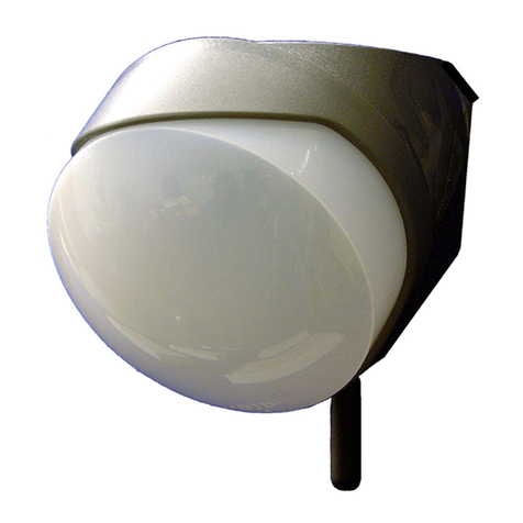
Innotech SENW51 User manual

© MASS ELECTRONICS Pty Ltd 2014
MODELS:
SENW51: Temperature Detector
SENW58F: Fahrenheit model, with display, setpoint adjustment and override
SENW58C: Celsius model with display, setpoint adjustment and override
Overview
The SENW5x Wall Mounted Temperature Detector is a wall mounted
sensing element used for the monitoring of temperature in a
controlled space.
DS 1.29
December 2015
SENW5x
Wall Mounted Temperature Detector
Applications
The Innotech SENW5x is designed to provide simple but accurate
sensing of air-conditioned spaces.
The detector provides an easy to read visual display of temperature,
and allows programming modifications using the intuitive LCD and
push button interface (SENW58 model only).
Features
• Icon based backlit Liquid Crystal Display (LCD)
• Modern, attractive enclosure design
• Wall mounted
• Displays Temperature and Setpoint at a glance
• Onboard temperature sensor
• Displays Fahrenheit (°F) or Celsius (°C)
• Push button interface for:
a. Temperature setpoint adjustment
b. Occupancy override
• Display available on SENW58 model only
• Temperature setpoint adjustment and override available on
SENW58 model only.
Installation / Wiring
The SENW5x detector should be installed in an environment that
does not exceed the maximum operating parameters of the device.
It should be mounted in a clean and dry environment free of
vibration, and properly ventilated.
The SENW5x should be mounted with a standard vertical C-Clip,
or on a standard wall enclosure. Maximum terminal cable entry is
2.5mm² (stranded conductor).
Wiring should be done in accordance with Innotech connection
diagrams and local bylaws or refer to your local distributor.
Connect the power supply to the correct terminals on the detector,
observing the correct polarity of the connections.
SENW58F
SENW51

© MASS ELECTRONICS Pty Ltd 2014
Page 2
DS 1.29 - SENW5x - Wall Mounted Temperature Detector
December 2015
Specifications
POWER SUPPLY REQUIREMENTS (SENW58 Only)
Power Input 24VDC or 24VAC ±10% @ 50/60Hz
Power Consumption 10mA @24VDC (80mA w/ backlight on)
Polarity MUST be observed when connecting power.
If using 24VAC, the data and power cabling should be segregated and
data run in screened cable (as shown on page 5).
ENVIRONMENTAL
Operating Temperature 32°F to 104°F (0 to 40°C)
non-condensing
Storage Temperature 32°F to 122°F (0 to 50°C)
non-condensing
ENCLOSURE
Housing is moulded from flame retardant plastics recognised by UL
as UL94-V0. The housing is designed to maximise airflow to the onboard
sensors. It should be mounted with a standard vertical C-Clip, or on a
standard wall enclosure.
Colour Grey / White
Dimensions(Maximum) (W)2.76" x (H)4.76" x (D)1.6"
[70mm x 121mm x 41mm]
APPROVALS
EN61326-1:2013 for CE Marking and RCM Labelling
Title 47 CFR, Part 15, Subpart B, Class A for FCC Verification
Onboard Sensor
TEMPERATURE SENSOR
Resistance NTC 10,000Ω thermistor (10K-2)
Accuracy ±0.36°F (0.2°C)
from 32 to 158°F (0 to 70°C)
Inputs and Outputs
AVAILABLE OUTPUTS
Temperature Temperature (Temp) Resistance,
10K-2 thermistor (Isolated)
Setpoint (STPT) 0 to 10VDC = configurable setpoint
signal (ref. to power GND)
OCCUPIED INPUT
Occupancy (OVR)
Occupied = 10VDC ("Man" displayed)
Unoccupied = 0VDC
("Man" not displayed)
(ref. to power GND)
Controls and Display
CONTROLS (SENW58 Only)
Setpoint Up and Down Buttons
Override / Select Single Button
DISPLAY (SENW58 Only)
Backlit LCD for Temperature, Setpoint and Override
Primary Display Four Numeric Digits 0.75" (19mm) high
with one selectable decimal
Secondary Display Four Numeric Digits 0.5" (12.7mm) high
with one selectable decimal
Icons / /
Display Size (Width x Height) 1.6" x 1.2" (40mm x 30mm)
Digit Resolution 0.1, 0.5 or 1
Units °F, °C
Temperature Oset Range ±10
SET
Up
Down
Override /
Select
Primary
Display
Secondary
Display
DAY MONTH
ON
SET
START STOP
ppm
kWh
Setpoint Indicator
Numeric / Text
Primary Display
Override Status
Numeric / Text
Secondary Display
Temperature
Indicators
1.6” (41mm)
1”
(26mm) 0.6”
(15mm)
4.76" (121mm)
2.76" (70mm)
SENW5x Dimensions and Identification
(SENW58F Shown)
SENW58 LCD Display
1"
(26mm) 0.6"
(15mm)
1.6" (41mm)

© MASS ELECTRONICS Pty Ltd 2014
Page 3
DS 1.29 - SENW5x - Wall Mounted Temperature Detector
December 2015
Operation Sequence and Display (SENW58 Only)
Power
• The SENW5x is powered by 24VDC or 24VAC ±10% from
terminals (VIN) and (GND).
• Terminal (GND) is common for power and setpoint outputs,
and reference for the 0/10VDC input for override.
• A Display segment test is performed by pushing and holding
the Override button during power-up. This action will latch
all the segments ON until the override is released.
Sensors
• Temperature is measured by a 10K-2 type thermistor.
• Temperature is viewed on the Primary Display.
Temperature Setpoint
• The setpoint is adjusted by the Up and Down buttons. A 0
to 10VDC signal is produced from terminal (STPT). The range
may be adjusted, unless configured for "Setpoint Lockout".
• The setpoint is viewed on the secondary display.
• The setpoint ranges from 55°F (12°C) to 95°F (35°C) absolute
temperature or as a relative temperature from ±5° (F or C).
The setpoint range is dependent on the settings for P3 and P4.
• The primary display shows the temperature setpoint during
adjustment. It will revert back to the temperature 5 seconds
aer the last button activity.
• 0.5° increments for SENW58F model.
• 0.1° increments for SENW58C model.
Override
• The override is activated by the Override pushbutton on
the front of the SENW58. When pressed, the temperature
sensor will short circuit for 5 seconds, unless configured for
"Occupancy Lockout".
• When the temperature input on the Innotech Maxim/Genesis
controller registers the fault from the SENW58 sensor short
circuit, the analogue output from the controller changes from
0VDC (o) to 10VDC (on).
• When the SENW58 detector registers 10VDC from the
controller, the " " is displayed to represent "Occupied"
mode.
• When the SENW58 detector registers 0VDC from the controller,
the " " is not displayed to represent "Unoccupied" mode.
Display
• Primary Display - Indicates Temperature in °F or °C depending
on the version of detector (F/C). This also displays the setpoint
when the Up/Down buttons are pressed. (This may be
adjusted to toggle between Temp and Setpoint - P7)
• Secondary Display - Indicates Temperature Setpoint. - P8
• The display can be adjusted for resolutions of 0.1, 0.5 or 1.
• The backlit display has two modes, “Active” and “Inactive”.
❒ Active - When a button press is detected the display will
illuminate.
❒ Inactive - When no button activity is detected for 5 seconds
the display will become dull.
• The " " is displayed on the SENW58 to indicate "Occupied"
or "Unoccupied" modes. (Refer to the Typical Configuration)
• "E" will be displayed if there is an error with the SENW58
sensor.
Parameters (SENW58 Only)
The SENW5x is factory set, as per the Parameters on page 4. These may
be adjusted using the Up/Down and Select buttons.
• Where [°F Default] or [°C Default] is indicated, this is the default for
the respective Fahrenheit or Celsius models.
• Where [Factory Default] is specified, it is the default setting
regardless of the model.
Enter the Parameter Menu
The parameter menu is accessed by a two step procedure.
1. Simultaneously press and hold the Up and Down buttons for 3
seconds. will be displayed.
2. Continue to hold the Up and Down buttons and also hold the
Select button for 3 seconds.
Aer successfully entering the Parameter Menu, the initial parameter
displayed will be P1.
You may modify multiple parameters before returning to the normal
mode of operation.
Setting Parameters
1. Press the Up/Down Buttons to select a setting from P1 to P13. The
parameter number will be displayed in the Primary display (The
Parameters are detailed on the next page).
2. Press the Select Button to modify the specific parameter to
change. The parameter number will drop to the secondary display
and the primary display will be used for parameter changes.
3. Change the parameter value using the Up/Down buttons.
4. Press the Select Button to save the changes.
5. If required, press the Up/Down Buttons to select the next
parameter.
Exiting the Parameter Menu
To exit the Parameter menu, press the Up, Down & Select buttons
together.
Alternatively the display will automatically revert aer button inactivity
for 30 seconds.
MONTH
ON START STOP kWh
Parameter Menu Parameter 2 Options
Selecting and Modifying a Parameter
• Refer to the typical configuration for programming of your Innotech
Controller.
• Where used, P# refers to a Parameter number. ie: P1 = Parameter 1.

© MASS ELECTRONICS Pty Ltd 2014
Page 4
DS 1.29 - SENW5x - Wall Mounted Temperature Detector
December 2015
Parameter 1: Set Temperature Display Units
This parameter determines whether the temperature is
displayed in °C or °F.
• Sets output in °F
• Sets output in °C [°C Default]
• Sets the display and outputs to read in °F [°F Default]
• Sets the display and outputs to read in °C
•Selecting will display the F or C beside the temperature.
•The setting used in P1 determines the units used globally (°F or °C).
Parameter 2: Temperature Setpoint Type
This parameter sets the setpoint display to either absolute (xx to yy°)
or Relative (±x°) on the display.
• Absolute value (xx° - yy°) [Factory Default]
• Relative value (±xx)
• eg. ABS = 72.5°F
REL = -2.2°F
The setting used in P2 determines the SP Type used in P3 & P4.
Parameter 3: Temperature Setpoint Minimum Value
This parameter sets the minimum value for the setpoint.
Eng
Units
SP
Type Function
Adjust value from 55.0 to 69.0°F, (increments of
0.5°F), Default = 65°F [°F Default]
Adjust value from 12.0 to 20.0°C, (increments of
0.1°C), Default = 18°C [°C Default]
or Adjust value from -5° to 0°, (increments of
0.5°F/0.1°C), Default = -3°
•This setting is dependent on the values selected in P1 and P2.
•If altering P3, you must alter the setpoint range minimum in your
soware programming.
Parameter 4: Temperature Setpoint Maximum Value
This parameter sets the maximum value for the setpoint.
Eng
Units
SP
Type Function
Adjust value from 69.0 to 95.0°F (increments of
0.5°F), Default = 85°F [°F Default]
Adjust value from 20.0 to 35.0°C (increments of
0.1°C), Default = 29°C [°C Default]
or Adjust value from 0° to +5°, (increments of
0.5°F/0.1°C), Default = +3°
•The setting is dependent on the values selected in P1 and P2.
•If altering P4, you must alter the setpoint range maximum in your
soware programming.
Parameter 5: Temperature Setpoint Lockout
This parameter enables or disables the adjustment of the setpoint.
• This setting locks the setpoint at the current value and
disables the Up/Down buttons
• This setting enables the setpoint to be changed by the
user using the Up/Down buttons [Factory Default]
Parameter 6: Occupancy Lockout
This parameter enables or disables the override button function.
• This setting disables the Override button
• This setting enables the Override button so the user
can request occupancy override [Factory Default]
Parameter 7: Set Primary Display Mode
This parameter determines what is shown on the primary display.
• The primary display is not used
• Temperature value only [Factory Default]
• Temperature and setpoint values alternate every 5
seconds
• Room temperature setpoint value only
Parameter 8: Set Secondary Display Mode
This parameter determines what is shown on the secondary display.
• The secondary display is not used
• Room temperature setpoint value only [Factory Default]
Parameter 9: Display Resolution
This parameter sets the resolution for the digital display.
• Sets a 0.1 resolution (xx.1) [Factory Default]
• Sets a 0.5 resolution (xx.5)
• Sets whole number resolution (1)
Parameter 10: Backlight Duration
This parameter selects the backlight duration.
• 1-10 Adjust the setting using the Up or Down buttons
[Factory Default = 5 seconds]
Parameter 11: Temperature Sensor Calibration
This parameter adjusts the temperature display value ±10°.
• -10 to +10 Adjust value ±10° in 0.1° increments
[Factory Default is 0°]
Calibration of the display and the sensor input (at the controller) is
required.
Parameter 12: Sensor Firmware Version
This parameter displays the current firmware in the SENW58.
• 1.0 Example of firmware version
Parameter 13: Reset to Factory Defaults
The SENW58 may be reset to factory defaults.
1. Select P13, will be displayed.
2. Press the Up button, will be displayed.
3. Press the Select button, will be displayed and the
sensor program will revert to the factory default values. Normal
operation will begin aer the reset is complete.
The SENW58 sensor is factory calibrated.

© MASS ELECTRONICS Pty Ltd 2014
Page 5
DS 1.29 - SENW5x - Wall Mounted Temperature Detector
December 2015
SENW5x Detector Connection Identification
SENW58x Connection Diagram - 24VDC SENW58x Connection Diagram - 24VAC
SENW58x
GND
VIN
OVR
STPT
Temp
Temp
10VDC / 0V Input
0 to 10VDC Output
Thermistor (Temp +)
Thermistor (Temp -)
0V / GND
24VAC
From
Power Supply
From Controller
Output
(0VDC=o, 10VDC=on)
To Controller
Inputs
SENW58x
GND
VIN
OVR
STPT
Temp
Temp
10VDC / 0V Input
0 to 10VDC Output
Thermistor (Temp +)
Thermistor (Temp -)
0V / GND
24VDC
From
Power Supply
From Controller
Output
(0VDC=o, 10VDC=on)
To Controller
Inputs
Maximum terminal cable entry is 2.5mm² (stranded conductor).
FCC Class A Notice
This device complies with Part 15 of the FCC Rules. Operation is subject to the following two conditions:
1. This device may not cause harmful interference.
2. This device must accept any interference received, including interference that may cause undesired operation.
Note – This equipment has been tested and found to comply with the limits for a Class A digital device, pursuant to Part 15 of the FCC Rules. These limits are designed to provide reasonable
protection against harmful interference when the equipment is operated in a commercial environment. This equipment generates, uses and can radiate radio frequency energy and, if not
installed and used in accordance with the instruction manual, may cause harmful interference to radio communications.
Operation of this equipment in a residential area is likely to cause harmful interference in which case the user will be required to correct the interference at his own expense. Modifications to this
device, may void the authority granted to the user by the FCC to operate this equipment.
Polarity MUST be observed when connecting power.
Earth screens at controller only.
• When using 24VDC to power the device, a single shielded cable
may be used for power and control signals.
• Link is required if override is not used.
• Maximum terminal cable entry is 2.5mm² (stranded conductor).
Polarity MUST be observed when connecting power.
Earth screens at controller only.
• When using 24VAC to power the device, separate cables must be
used for power and control signals.
• Link is required if override is not used.
• Maximum terminal cable entry is 2.5mm² (stranded conductor).
Gnd
VIN
OVR
STPT
Temp
Temp
SENW58x Detector
CONNECTOR INFORMATION
Connector Description
Gnd Power Common / Neutral
VIN + Power 24VDC or 24VAC ±10%
OVR Override Input
(10VDC = Occupied, 0VDC = Unoccupied)
STPT Setpoint Output
0 to 10VDC (Ref. to GND Common)
Temp Temperature Sensor (Isolated)
Temp
SENW58xSENW51
Temp
Temp
3.45" (87.6mm)0.32" (8mm)
SENW51 Detector
CONNECTOR INFORMATION
Connector Description
Temp Temperature Sensor (Isolated)
Temp

© MASS ELECTRONICS Pty Ltd 2014
Page 6
DS 1.29 - SENW5x - Wall Mounted Temperature Detector
December 2015
Typical Configuration
YOUR DISTRIBUTOR
Australian Owned, Designed & Manufactured
by Mass Electronics Brisbane
Phone: +61 7 3421 9100 Fax: +61 7 3421 9101
Email:
[email protected] www.innotech.com.au
The INNOTECH device and the word INNOTECH are registered or unregistered trademarks of Mass Electronics Pty Ltd in Australia, USA and other countries
Configurations are available from the Innotech Website by clicking here.
Please note that the Fault Limits should be set as shown. Please note that the Fault Value should be set as shown.
This manual suits for next models
2
Table of contents
Other Innotech Security Sensor manuals
Innotech
Innotech AIO-GLEIT-12 User manual
Innotech
Innotech FSG 01 User manual

Innotech
Innotech QUADRAT-11 User manual
Innotech
Innotech FAS 01 Operating and maintenance manual
Innotech
Innotech Vaisala WXT User manual
Innotech
Innotech AIO-ENDS-10 User manual
Innotech
Innotech BEF 401-12 User manual
Innotech
Innotech EAP-QUADRAT-10 User manual
