INR LINC 21 User manual
170401
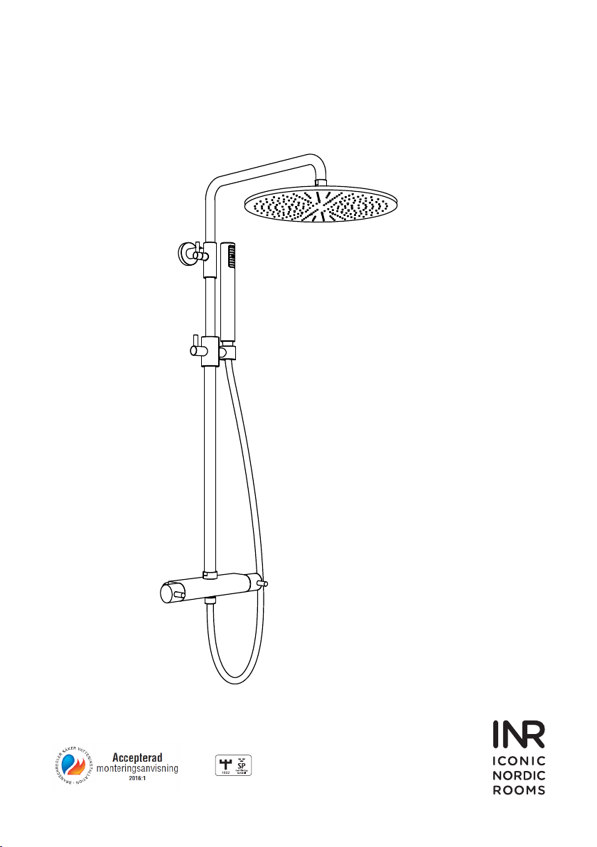
TAKDUSCH
LINC 21

2 ((12))
Innehåll/Index:
Innan montering 3
Tekniska specikationer 3
Rörarbeten och montering 3
Montering 150 cc och 160 cc DUSCHBLANDARE 3
Installation DUSCHSET 3
Användning 3
Filterbyte och rengöring 150 cc DUSCHBLANDARE 4
Filterbyte och rengöring 160 cc DUSCHBLANDARE 4
Insatsbyte och rengöring 4
Omställning av insatsen 4
Utbyte av omkastaren 4
Rengöring 4
Before installation 5
Technical features 5
Plumbing and installation 5
Installation 150 cc and 160 cc SHOWER MIXER 5
Installation SHOWER KIT 5
Operation 5
Filter change and cleaning 150 cc SHOWER MIXER 6
Filter change and cleaning 160 cc SHOWER MIXER 6
Cartridge change and cleaning 6
Cartridge re-setting 6
Diverter change 6
Cleaning 6
Sprängskiss/Exploded view 150 cc 7
Sprängskiss/Exploded view 160 cc 8
Skruvinfästningsskisser/Screwfastenerssketches 9
Flödes shema / Flow rate 10
RSK / INR art nr 10
Kontaktinformation / Contactinformation 12

3 ((12))
Före montering
Vi förordar en sakkunnig VVS-installatör vid installation och service. Ledningarna ska renspolas innan installation.
LINC 21 DUSCHBLANDARE inkl. TAK OCH HANDDUSH
Tekniska specikationer
Termostatblandaren är typgodkänd SP (SC0251-14) mer info om typgodkänning nns på www.sp.se
Godkänd för installation PN10 trycktester enligt EN1111:2000 (täthetstest 16 bar/deformationstest 25 bar)
Efter tappstället skall tappvarmvatten vara min 50ºC och max 60ºC.
Tappkallvattnet skall vara kallt och ej utsatt för ofrivillig uppvärmning. Temperatur över 20ºC är ej lämpliga.
Arbetstryck på varm- och kallvattens matningar skall hållas så balanserad som möjligt och från en gemensam källa för att
uppnå bästa möjlig funktion.
Rörarbeten och montering
• Fristående matningar är nödvändigt både för varmt och kallt vatten.
• Långa rördragningar orsaker tryckförluster.
• Om mer än en blandare är installerad se till att konstant matning av varmt och kallt vatten kan säkras.
• Varmvatten skall alltid kopplas på blandarens vänstra anslutning.
• Stäng alltid huvudkranen vid arbeten på vattenledningar.
• Skölj ledningar efter rörarbeten och innan installationen.
Montering 150 cc och 160 cc DUSCHBLANDARE
• Vi rekommenderar att montering sker på godkänd blandarskena alt väggdosa.
• Kontrollera att temperaturreglaget nns på höger sida.
• När monteringen är klar öppna huvudkranen och kontrollera att det inte nns några läckor.
Installation DUSCHSET
Kontrollera att det inte nns gömda elkablar eller vattenledningar innan hål borras i väggen.
• Placera väggfästet (G) på vertikalrörets konsol (H).
• Montera vertikalröret (B) på blandaren, använd packningen (A) och bestäm position för xering av väggfästet samt
märk ut på väggen.
• Skruvinfästningar ska göras i massiv konstuktion såsom betong, reglar, särskild konstuktionsdetalj eller i våtrumsvägg
2012. Skruvinfästningar får inte göras enbart i golv- eller väggskiva (SäVa § 2.11.1 & Våtrumsvägg 2012). Se
detaljerade skisser sidan 8-9.
• Plocka ner vertikalröret och borra hål till plugg och skruv (E).
• Fäst väggfästet (G) på väggen med de medföljande skruvarna (E) och montera väggfästets lock (D) över den.
• Montera vertikalröret (B) på blandaren, dra åt muttern och se till att använda den medföljande packningen (A).
• För in armen på konsolen (H) i väggfästet (D+G) och xera den genom att dra åt låsskruven (F).
• Anslut den koniska änden av duschslangen till handduschen (I) och därefter den andra änden till botten utloppet på
blandaren. Glöm ej att montera packningarna i var sin ände av slangen.
• Skruva fast takduschen (K) på vertikalröret med packningen (J) på plats.
• För att justera höjden på takduschen (K) vrid spaken på konsolen (H) och justera till önskad position.
Användning
För att reglera vattenödet vrid ödeshandtaget (9) moturs för att slå på och öka ödet till takduschen, vrid medurs för att
slå på och öka ödet till handduschen.
För att reglera vattnets temperatur, vrid temperaturhandtaget (3) medurs för att minska vattnets temperatur, moturs för att
öka den.
Blandaren är fabriksinställd på 38°C. För att nå högre temperatur, håll knappen intryckt och vrid handtaget moturs.

4 ((12))
Filterbyte och rengöring 150 cc DUSCHBLANDARE
• Stäng av vattentillförseln till blandaren.
• Avlägsna blandaren genom att lossa muttrarna (13) från blandarskena alt. väggdosa.
• Filtren (14) kan kvarstå i muttrarna (13) eller på blandarskena alt. väggdosa. Ta bort dem försiktigt.
• Tvätta ltren (14) under rinnande vatten eller låt dra i vinäger eller avkalkningsmedel.
• Sätt tillbaka ltren efter ovanstående förfarande i omvänd ordning.
• Se avsnitt ”Rörarbeten och montering” för montering av blandaren.
Filterbyte och rengöring 160 cc DUSCHBLANDARE
• Stäng av vattentillförseln till blandaren.
• Skruva loss muttrarna på blandarfästet från kopplingarna (13) och ta bort blandaren från väggen.
• Tag försiktigt bort låsringen (16) och tag ut ltret (15).
• Tvätta ltren (15) under rinnande vatten eller låt dra i vinäger eller avkalkningsmedel.
• Sätt tillbaka ltren efter ovanstående förfarande i omvänd ordning.
• Se avsnitt ”Rörarbeten och montering” för montering av blandaren.
Insatsbyte och rengöring
• Stäng av vattentillförseln till blandaren.
• Lirka av täckhatten (1) och lossa skruven (2) för att kunna avlägsna temperaturhandtaget (3).
• Ta bort stoppringen (4).
• Skruva loss insatsen (5) från blandaren försiktigt så att inte tätningarna skadas. Tvätta insatsen under rinnande vatten
eller låt dra i vinäger eller avkalkningsmedel.
• Innan återmontering av insatsen rengör insidan på blandarhuset och fetta in O-ringarna.
• Placera insatsen i blandarehuset och dra åt den till 15 Nm (med momentnyckel).
• Sätt på vattnet igen. Mät vattentemperaturen med en termometer. Ställ blandad temperatur till 38°C. För att göra detta
hänvisas till avsnitt ”Omställning av insatsen ”
• Återmontera stoppringen (4) i sitt ursprungliga läge.
• Återmontera temperaturhandtaget (3) så att stiften inuti handtaget är intill stoppen på övre delen av stoppringen (4).
Se till att 38°C etsningen på höljet är i linje med HOT etsningen på kroppen.
Omställning av insatsen
Blandaren är fabriksinställd på 38°C. Det kan justeras för lokala förhållanden eller personliga preferenser på följande sätt:
• Använd en vanlig hushållstermometer för att testa vattentemperaturen.
• Ta bort temperatur handtaget (3) genom att lirka ut täckhatten (1) och lossa skruven (2).
• Ta bort stoppringen (4) och notera positionen.
• Vrid axeln på insatsen (5) medurs eller moturs tills önskad temperat har uppnåtts.
• Återmontera stoppringen (4) i sitt ursprungliga läge.
• Placera temperatur handtaget (3) så att stiften inuti handtaget är intill stoppen på övre delen av stoppringen (4). Se till
att 38°C etsningen på höljet är i linje med HOT etsningen på kroppen. Fäst den med låsskruven (2) och placera sedan
täckhatten (1).
Utbyte av omkastaren
• Stäng av vattentillförseln till blandaren.
• Skruva av spaken (12) och lossa stoppskruven (10) för att avlägsna ödeshandtaget (9).
• Ta bort stoppringen (7).
• Skruva loss och tag bort omkastaren (6) försiktigt från blandaren så att inte tätningarna skadas.
• Placera den nya omkastaren (6) i blandaren och se till att använda plasthylsan (8). Dra åt stoppringen (7) till 8 Nm
(med moment nyckel) och återmontera handtaget i omvänd ordning.
• När monteringen är klar öppna huvudkranen och kontrollera att det inte nns några läckor.
Rengöring
Ytan rengörs med mjuk trasa och mild tvållösning. Skölj därefter med rent
vatten och torka med en mjuk torr trasa. Vid kalkäckar ska ättika användas.
Rengör taksilens gummidetaljer regelbundet genom att ”massera” dessa med handen.
För mer information besök vår web på www.inr.se

5 ((12))
Before installation
We recommend that an authorised plumber is contacted for installation and service.
Piping should be ushed prior to assembly.
LINC 21 SHOWER MIXER incl. OVERHEAD SHOWER AND HAND
SHOWER
Technical features
Thermostatic mixer is approved by SP (SC0251-14) for more information see approval available on www.sp.se/en
Approved for installation PN10 pressure tests according Temperature at the tapping point must be minimum 50ºC and
maximum 60°C.
Cold water tapping point should not be subjected to involuntary heating. Temperatures above 20ºC are not suitable.
Operating pressures on hot and cold line should be kept as balanced as possible, and from a common source, in order to
ensure the maximum efciency of the mixer.
Plumbing and installation
An independent water supply both for hot and cold is required.
Large runs of pipework will cause frictional loss of pressure.
If more than one shower valve is installed ensure constant supply of hot and cold water can be maintained.
Hot water supply must always be on the left inlet.
Shut down water supply when plumbing and installing.
Carefully ush pipework before commencing installation.
Installation 150 cc and 160 cc SHOWER MIXER
• We recommend the installation is done using an approved mixing rail or wall box.
• Make sure the temperature regulator are on the right side.
• When the installation is complete, open the main valve and make sure there are no leaks.
Installation SHOWER KIT
Prior to drilling into walls, check there are no hidden electrical wires, cables or water supply pipes.
• Position the wall bracket (G) on to the console (H) of the rigid riser.
• Fix the rigid riser (B) to the mixer screwing the nut to the mixer’s top outlet, use the supplied washer (A) and decide
correct position using the wall bracket as a template.
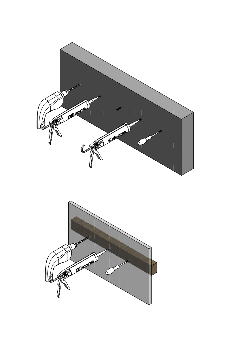
• Screw fasteners shall be made in massive construktions such as concrete, studs, special construction detail or
“Våtrumsvägg 2012”. Screw xings shall not be made solely in the oor or wall plate (SäVa § 2.11.1 & “Våtrumsvägg
2012”). See detailed sketches page 8-9.
• Disassemble the rigid riser from the mixer and drill holes to suit the screws (E).
• Fix the wall bracket (G) to the wall using the supplied screws (E) and place the wall bracket cover (D) over it.
• Secure the rigid riser (B) to the mixer tightening the nut and make sure to use the supplied washer (A).
• Insert the back stem of the console (H) into the wall bracket (D+G) and x it by tightening the grub screw (F).
• Connect the conical end of the shower hose to the handset (I) and the other end to the bottom outlet of the mixer
paying attention to insert the small sealing washers supplied with the exible hose on both sides.
• Fit the shower rose (K) to the rigid riser with washer (J) in its place.
• To adjust the height of the shower rose (K) twist the small lever on the console (H) and regulate the top part of the rail
as required.
Operation
In order to regulate the water ow turn the handle (9) counterclockwise to turn on and increase the ow to the head shower,
turn clockwise to turn on and increase the ow to the hand shower.
In order to regulate the water temperature, turn temperature handle (3) clockwise to decrease the water temperature and
counterclockwise to increase it.
The mixer is factory set at 38°C. If you need to reach higher temperature, press the button and turn the handle
counterclockwise.

6 ((12))
Filter change and cleaning 150 cc SHOWER MIXER
• Shut down water supply to mixer.
• Remove the mixer by loosening the nuts (13) from the mixing rail or wall box.
• The lters (14) can remain in the nuts (13) or on rail or mixes. wall box. Remove them carefully.
• Wash lters (14) under running water or leave to soak in vinegar or de-scaling agent.
• Ret the lters the above procedure in the reverse order.
• See paragraph “Plumbing and installation” for retting.
Filter change and cleaning 160 cc SHOWER MIXER
• Shut down water supply to mixer.
• Unscrew the nuts of the xing plate from the seats (13) and remove the mixer from the wall.
• Carefully remove the circlip (16) and take out the lter (15).
• Wash lters (15) under running water or leave to soak in vinegar or de-scaling agent.
• Ret the lters following the above procedure in the reverse order.
• See paragraph “Plumbing and installation” for retting.
Cartridge change and cleaning
• Shut down water supply to the mixer.
• Prise-off the cap (1) and undo grub screw (2) in order to remove the temperature handle (3).
• Remove the stop ring (4).
• Unscrew and remove the cartridge (5) from the mixer being careful not to damage the seals. Wash the thermostat
under running water or leave to soak in vinegar or de-scaling agent.
• Before retting the cartridge clean the mixer housing and grease the valve o-rings.
• Place the cartridge into the mixer and tighten it at 15 Nm.
• Turn the water supply back on. Measure water temperature with a thermometer. Set the mixed ow temperature at
38°C. See paragraph “Cartridge re-settning”.
• Re-t the stop ring (4) in its original position.
• Re-t the temperature handle (3) so that the pin inside the handle is next to the stopper on the upper part of the stop
ring (4). Make sure that the 38°C etching on the lever is aligned with the HOT etching on the body.
Cartridge re-setting
The mixer is factory set at 38°C. This can however be adjusted for site conditions or personal preference. In order to do this,
proceed as follows:
• Use a common household thermometer to test water temperature.
• Remove the temperature handle (3) by prising off indice (1) and undoing grub screw (2).
• Remove the stop ring (4) taking note of its position.
• Turn the spindle of the cartridge (5) clockwise or anticlockwise until the desired temperature is reached, paying
attention not to damage the broached part.
• Re-t the stop ring (4) in its original position.
• Place the temperature handle so that the pin inside the handle is next to the stopper on the upper part of the stop
ring (4), making sure that the lever is pointing downwards and the 38°C etching on the lever is aligned with the HOT
etching on the body. Fix it with the grub screw (2) and then place the cap (1).
Diverter change
• Shut down water supply to the mixer.
• Unscrew lever (12) and undo grub screw (10) in order to remove the ow handle (9).
• Unscrew the stop ring (7) and remove the diverter (6) from the mixer being careful not to damage the seals.
• Place the new diverter into the mixer making sure to use the broached insert (8) and tighten the stop ring (7) at 8 Nm
and re-assemble the handle following the above procedure in the reverse order.
• Turn the water supply back on and check for leaks.
Cleaning
Chromed surfaces should be cleaned using a soft cloth and a mild soap solution. The surface should then be ushed with
clean water and dried using a soft dry cloth. Use household vinegar for removing lime scale from chromed surfaces.
Clean shower rose rubber parts regularly by “massaging” them with your hand.
For more information visit our website at www.inr.se
7 ((12))
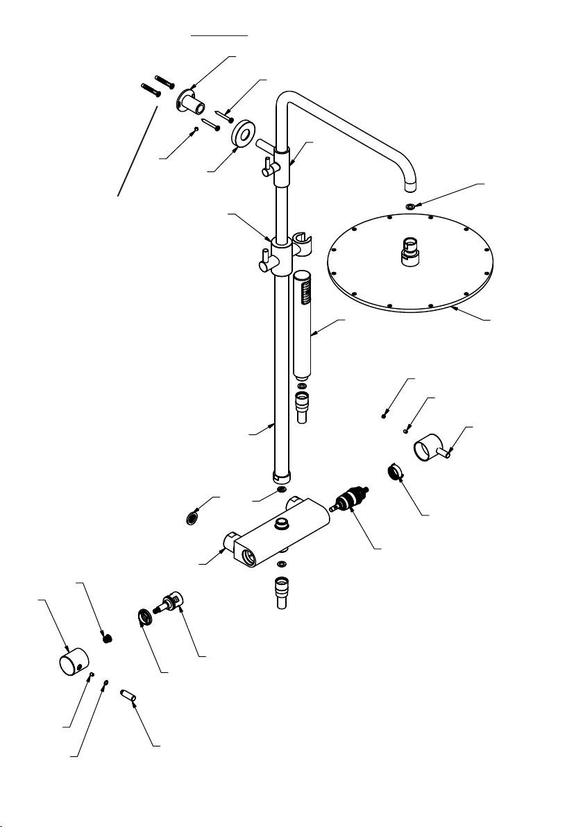
LINC 21 150 cc Kombiset/Shower Column
IK
J
5
7
6
A
14
13
4
3
2
1
8
9
10
11
12
B
G
E
F
D
C
H
Infästning Se sida 9-10 /
Attachment See page 9-10

8 ((12))
LINC 21 160 cc Kombiset/Shower Column
7
6
J
K
5
16
15
14
A
13
4
1
2
3
8
12
11
10
9
B
C
D
E
F
G
I
H
Infästning Se sida 9-10 /
Attachment See page 9-10
9 ((12))
1.
2.
3.
4.
5.
1. 2.
3.
Betong/Concrete
Regel/Studs
10 ((12))
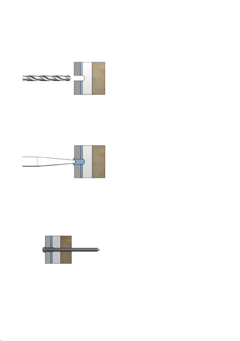
Våtrumsvägg 2012
1. Borra endast genom ytskikt och tätskikt.
OBS! Borra aldrig genom plywooden.
Drill only through the outer layer and waterproong.
NOTE! Never drill through the plywood.
2. Fyll hela hålet med åldersbeständig tätningsmassa.
Fill the entire hole with age-resistant sealant.
3. Använd VVS-skruv. Skruva genom plywoodskivan. Use
plumbing screw. Screw trough the plywood sheet.

11 ((12))
Flödes schema / Flow rate
2 bar 3 bar 4 bar 5 bar
Takdusch 150 CC med 200 mm taksil
Shower system 150 CC with 200 mm shower rose
12L/m 15L/m 16L/m 16,60L/m
Takdusch 150 CC med 300 mm taksil
Shower system 150 CC with 300 mm shower rose
14,50L/m 16L/m 18L/m 19L/m
Takdusch 160 CC med 200 mm taksil
Shower system 160 CC with 200 mm shower rose
12,50L/m 15,60L/m 17L/m 18L/m
Takdusch 160 CC med 300 mm taksil
Shower system 160 CC with 300 mm shower rose
15L/m 16,50L/m 18,70L/m 20L/m
RSK Nr/No INR Art.Nr/Code No CC mm Taksil Ø mm/Shower Rose Ø mm
8191133 80000369 150mm 200mm
8191134 80000370 160mm 200mm
8191135 80000371 150mm 300mm
8191136 80000372 160mm 300mm

INR Försäljning
Sverige AB
Kosterögatan 15
211 24 Malmö
Sverige
Tel 0200-38 40 40
info@inr.se
www.inr.se
INR Norge AS
Fjordgaten 13
3125 Tønsberg
Norge
Tel +47 33 33 02 00
info@inr.no
www.inr.no
Sanka OY
Johtajantie 1
07900 Loviisa
Suomi
Tel +358 19 517 730
info@inr.
www.sanka.
INR Danmark A/S
Brogrenen 10
2635 Ishøj
Danmark
Tel +45 86 86 22 44
info@inr.dk
www.inr.dk
Other manuals for LINC 21
2
Table of contents
Languages:
Other INR Bathroom Fixture manuals

INR
INR MARK 800 00 Series User manual

INR
INR Tugela 0501 Series User manual

INR
INR EPIC 1 User manual

INR
INR INR basic Ramona User manual

INR
INR 80 000 583 User manual

INR
INR LINC 20 User manual

INR
INR BOW 80000637 User manual

INR
INR GRAND User manual

INR
INR ARC 30 User manual

INR
INR BASIC Ramona User manual


Popular Bathroom Fixture manuals by other brands


ZURN
ZURN Sundara Z5003.02 Installation, Maintenance, and Parts Manual

Tylo
Tylo STELLA 2900 3005 Installation & user guide

Kinedo
Kinedo Kinemagic Royal DES1310AG-D installation instructions

Glacier bay
Glacier bay 873W-4004 Use and care guide

Franke
Franke AQCT0050 Installation and operating instructions

FORENO
FORENO SYMPHONY SYM04 quick guide


