SeeMeCNC rostock max v2.0 User manual

Rostock MAX v2 Assembly Guide – 4thEd.
Welcome to the Assembly Guide for the Rostock MAX v2.0 3 printer.
Version 4.47, September 28th, 2016
Fourth Edition
Copyright 2016 by Gene Buckle
Licensed as Creative Commons Attribution-ShareAlike 3.0
Questions or corrections should be emailed to geneb@deltasoft.com
– 1
Rostock MAX v2 Assembly Guide – 4thEd.
Read Me First!
This document is your instruction manual for your new SeeMeCNC® 3D printer machine.
Before using your new 3D printer, thoroughly read and understand this manual for safe and effecti e
operation of the machine.
– 2
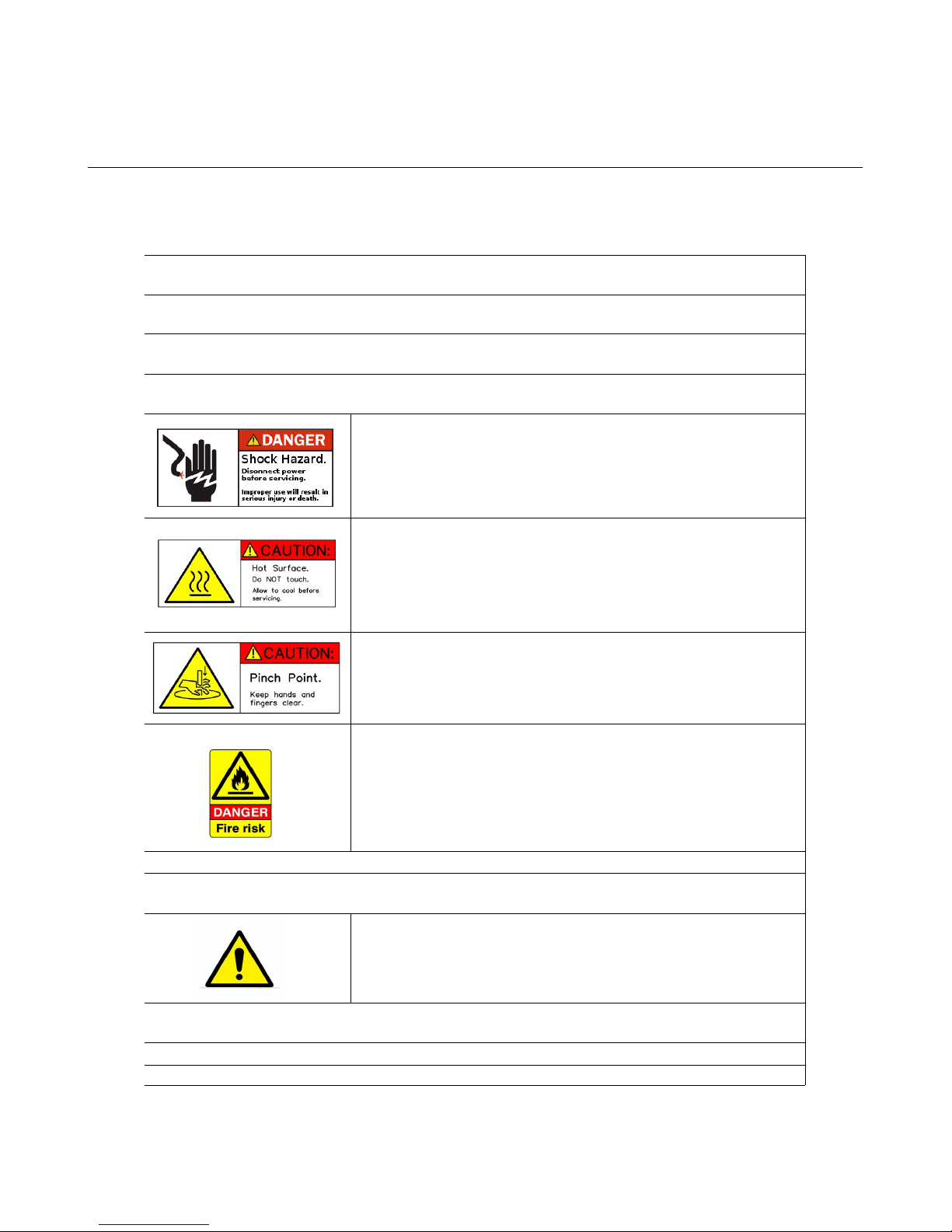
Warning
Adult supervision required. Children under 18 years of age require supervision.
Risk of Fire. Do not leave machine unattended.
Use genuine parts manufactured or designated y SeeMeCNC.
Keep a copy of this manual near the machine, easily accessi le to all operators.
Use of this machine is at your own risk.
Personal property damage, serious injury or death can result from not following
instructions or warning in the manual or misuse of the machine.
Automatic machine can start unexpectedly. Pay close attention and keep clear
while power is connected to the machine
The machine power supply is connected to AC voltage
and can e hazardous. Disconnect power efore
servicing this machine.
The hot end of the machine can reach very high
temperatures of 700F and can cause serious urns.
The heated print surfaces (heated ed) can also reach
temperatures high enough to cause severe urns. Allow
oth to cool for 20 minutes after turning off power.
Use caution near moving parts of the machine. Keep
ody and loose articles clear.
Poisonous gas, smoke, or fumes could e emitted y some materials you could
use with the machine. In such case, you should install ventilation.
Choking Hazard. This machine contains small parts and
can produce small parts which can e a choking hazard
to children.
Visit http://www.seemecnc.com to contact us if you have any questions.

Rostock MAX v2 Assembly Guide – 4thEd.
Table of Contents
REA ME FIRST!.....................................................................................................................................2
0 – Introduction and Acknowledgments....................................................................................................5
1 – Required Tools And Materials..............................................................................................................6
Tools.................................................................................................................................................6
Additional Materials.........................................................................................................................7
2 – Visual Bill of Materials........................................................................................................................9
3 – Preparing the Hot End and Power Supply.........................................................................................28
3.1 – Preparing the Hot End...........................................................................................................28
3.2 – Preparing the Power Supply..................................................................................................33
3.3 – Put a Ring (terminal) On It....................................................................................................35
3.4 – Attaching The Wiring To The Power Supply........................................................................36
4 – Preparing the Onyx Heated Bed.........................................................................................................38
4.1 – Installing The Thermistor......................................................................................................38
4.2 – Installing the Resistor and Power LE .................................................................................40
4.3 – Attaching the Thermistor and Power Wiring.........................................................................41
5 – Preparing the rive Motors................................................................................................................43
6 – Assembling the Base..........................................................................................................................44
6.1 – Installing The Feet.................................................................................................................45
6.2 – Installing the Cover Retention Screws & Threading the Panel Holes...................................46
6.3 – Installing the Vertical Support Retaining Nuts......................................................................48
6.4 – Installing the Vertical Supports and Power Supply Mount....................................................49
6.5 – Installing the Power Supply...................................................................................................51
6.6 – Connecting the Power Supply and Fitting the Side Panel.....................................................52
6.7 – Assembling the Tower Supports............................................................................................55
6.8 – Installing the Tower Supports................................................................................................59
6.9 – Installing the Base Top Plate.................................................................................................60
7 – Installing the Towers & Tower Wiring...............................................................................................62
7.1 – Running Wire in the Towers..................................................................................................62
7.2 – Setting the Towers.................................................................................................................66
8 – Assembling, Installing, and Wiring the Top Section..........................................................................68
8.1 – Prepping the Upper Tower Mounts........................................................................................68
8.2 – Installing the Upper Tower Mounts.......................................................................................69
8.3 – Installing the End Stop Switches...........................................................................................71
8.4 – Installing the Upper Tower Mounting Hardware...................................................................72
8.5 – Installing the Upper Idler Bearings........................................................................................73
8.6 – Attaching the Top Plate..........................................................................................................74
8.7 – Connecting the End Stop Switches........................................................................................76
8.8 – Routing the wires & binding them.........................................................................................77
8.9 – Tightening the Towers...........................................................................................................78
9 – Assembling & Installing the Carriages & Belts.................................................................................80
9.1 – Assembling the Carriage Rollers...........................................................................................80
– 3

Rostock MAX v2 Assembly Guide – 4thEd.
9.2 – Installing the End Stop Screws..............................................................................................82
9.3 – Installing the rive Belts and Carriages................................................................................82
9.4 – Assembling the Carriage Spring Arms..................................................................................84
9.5 – Installing the Carriages on the Towers..................................................................................86
9.6 – Attaching the Belts to the Carriage........................................................................................87
9.7 – Installing the Axle Adapters...................................................................................................88
9.8 – Adjusting the Belt Tension....................................................................................................88
10 – Assembling and Installing the EZStruder........................................................................................89
10.1 – Assembling the EZStruder...................................................................................................89
10.2 – Installing & Mounting the EZStruder..................................................................................92
10.3 – Wiring the EZStruder Stepper Motor..................................................................................96
11 – Installing the Hot End and Bowden Tube........................................................................................98
11.1 – Preparing the Hot End Wiring.............................................................................................98
11.2 – Hot End Prep......................................................................................................................100
11.3 – Wiring the Hot End............................................................................................................100
11.4 – Attaching the Hot End to the Hot End Mounting Plate.....................................................103
11.5 – Installing the Bowden Tube...............................................................................................104
12 – Installing the Effector Platform and elta Arms............................................................................105
12.1 – Assembling the Effector Platform.....................................................................................105
12.2 – Installing the Ball-Cup elta Arms & Effector Platform..................................................106
13 – Installing the Hot End....................................................................................................................108
14 – Finishing the Top End....................................................................................................................109
14.1 – Installing the Spool Holder................................................................................................109
14.2 – Installing the Top Plate and Spool Support Arm................................................................111
15 – Installing the Onyx Heated Bed.....................................................................................................114
16 – Assembling & Installing the LC Panel Mount............................................................................116
16.1 – Assembling the Front Panel...............................................................................................116
16.2 – Installing the LC Trim Panels.........................................................................................118
17 – Installing & Connecting the RAMBo Controller...........................................................................120
17.1 – Preparing the RAMBo Mounting Plate.............................................................................120
17.2 – Mounting the RAMBo Controller.....................................................................................121
17.3 – Wire Prep: End Stops.........................................................................................................123
17.4 – Wire Prep: The Hot End Thermistor Connector................................................................124
17.5 – Wire Prep: The Heated End Thermistor Connector...........................................................125
17.6 – Wire Prep: Extruder Motor Connector..............................................................................125
17.7 – Wiring the RAMBo Controller – Terminal Block.............................................................126
17.8 – Plugging cabling into the RAMBo....................................................................................128
17.9 – Installing the RAMBo Into The Machine Base.................................................................130
17.10 – Installing the Power Switch and LC Controller Cables................................................131
18 – Final Assembly Tasks.....................................................................................................................133
18.1 – Attaching the Base Covers & LC Panel..........................................................................133
18.2 – Attaching the USB Cable...................................................................................................134
18.3 – Installing the Acrylic Cover Panels...................................................................................135
18.4 – em Feet...and the Borosilicate Glass Build Plate!...........................................................137
18.5 – Smoke Test!.......................................................................................................................138
– 4

Rostock MAX v2 Assembly Guide – 4thEd.
0 – Introduction and Acknowledgments
I’d like to welcome you to the 4th Edition of the Rostock MAX v2 assembly guide!
Even if you've built an original Rostock MAX v1 3 printer, you'll want to read this manual
carefully. There are no common Melamine parts from the v1 design. The construction has been greatly
streamlined and should prove to be a shorter build. The design changes made will ensure that you've
got a long lasting, easy to calibrate, delta configuration 3 printer.
Please read this entire guide before you begin assembly of your new Rostock MAX v2! It will
help you avoid any unpleasant surprises and will ensure that you’ve got everything you need BEFORE
you need it! Understand that the photographs in this assembly guide do NOT tell the whole story of
each step! Make sure you read and understand the accompanying text for each step!
A quick note on the RAMBo, the controller for your Rostock MAX v2. The RAMBo is static
sensitive, so please don't take it out of the static bag it ships in until you're ready to use it.
The box containing the RAMBo and its wiring should also contain a printed, black & white
sheet that looks like this:
http://www.reprap.org/wiki/File:Rambo-conn-all.jpg
Please refer to this sheet when you reach Chapter 18. This is a valuable guide to wiring the
RAMBo up to your Rostock MAX v2. Note that the connector polarity is clearly marked on the board
for the “MOSFET Outputs”.
The Five Stages of Masking Tape...have been removed!
In a change from previous editions of the Rostock MAX v2 assembly guide, I'm going to spare
you the time consuming task of removing all the parts from the laser cut sheets at one time. For the 4th
Edition, you'll only “pull & peel” the parts as you need them. In order to help you locate the required
parts, each task section will show the part, what sheet it comes on, and how many of them you need.
This will also help avoid lost parts or parts that get thrown out accidentally.
Acknowledgments
I'd like to thank the gentleman that runs http://minow.blogspot.com.au/ for his excellent guide
on calibrating delta configuration 3 printers.
I'd also like to thank the whole gang over at the SeeMeCNC forums for providing excellent
feedback. This would be a much lesser creation without their contributions and insights.
0 – Introduction and Acknowledgments – 5
Rostock MAX v2 Assembly Guide – 4thEd.
1 – Required Tools And Materials
Before you begin assembly of your Rostock MAX v2, please make sure you’ve got everything
on the following list of tools and additional materials.
Tools
•P1 & P2 sized Phillips screwdrivers
•Standard flat head screwdriver
•A small flat head screwdriver.
•3/32” Allen (hex) wrench. A ball-end, T-handle version is a good choice for this and the other
sizes of Allen wrenches used
•5/32” Allen (hex) wrench.
•7/64” Allen (hex) wrench.
•Needle nose pliers
•Slip joint pliers
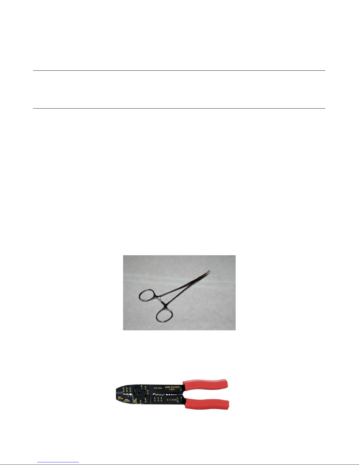
•Forceps – these will come in handy when routing the belts and reaching for small, hard to reach
parts. They can be purchased from Amazon for as little as $3.50 for a set of two.
•Wire strippers
•Wire cutters (flush cut type)
•Wire crimping tool, similar to the one below. Used for crimping power supply wiring.
1 – Required Tools And Materials – 6
Rostock MAX v2 Assembly Guide – 4thEd.
•5/16” open-ended wrench.
•11/16” open-ended wrench (used for hot-end mount)
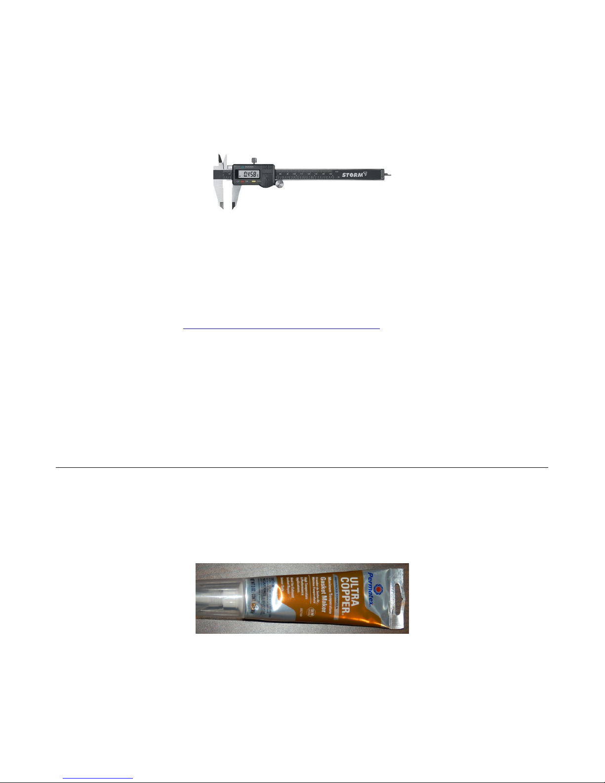
•A digital caliper. These can be purchased from Harbor Freight tools for around $10.
•A small squeeze clamp that can open at least 6”
•Battery powered screwdriver. If you ever needed an excuse to buy one of these, THIS IS IT.
•Pencil.
•40W Soldering Iron.
•Solder. (Example: https://www.sparkfun.com/products/9161)
•Blue thread locking compound (Loctite or Permatex Threadlocker Blue)
•A small file.
•12” framing square.
•A small razor knife like an X-Acto knife. This will be handy for cleaning the flashing off the
injection molded parts.
Additional Materials
•Toothpicks
•Isopropyl Alcohol
•1 Roll of ABS filament. Needed to print the fan shrouds at the end of the build.
•PermaTex Ultra Copper High Temp RTV
•1/2” wide roll of Kapton tape ($7-$10 at Amazon, search for “Kapton 1/2”.
•Elmer's Glue Stick – must be marked “ isappearing Purple”.
1 – Required Tools And Materials – 7

Rostock MAX v2 Assembly Guide – 4thEd.
The following is a list of optional things that can make your life easier in the long run.
•Electrician's tape.
•Standard sized nylon wire ties.
•Waxed lacing cord. You can use this in place of wire ties in pretty much any application. You
can find it here: http://www.skygeek.com/wht-string.html. While expensive, you'll never really
need to buy a wire tie again and it'll likely last you the rest of your life. :)
I'd also recommend a little plastic box with part compartments in it. They're really cheap at
craft stores and are perfect for building a kit like this – you can store all the various fasteners and have
them ready to go as you need them. Here's the one I use for my various projects:
1 – Required Tools And Materials – 8
Rostock MAX v2 Assembly Guide – 4thEd.
2 – isual Bill of Materials
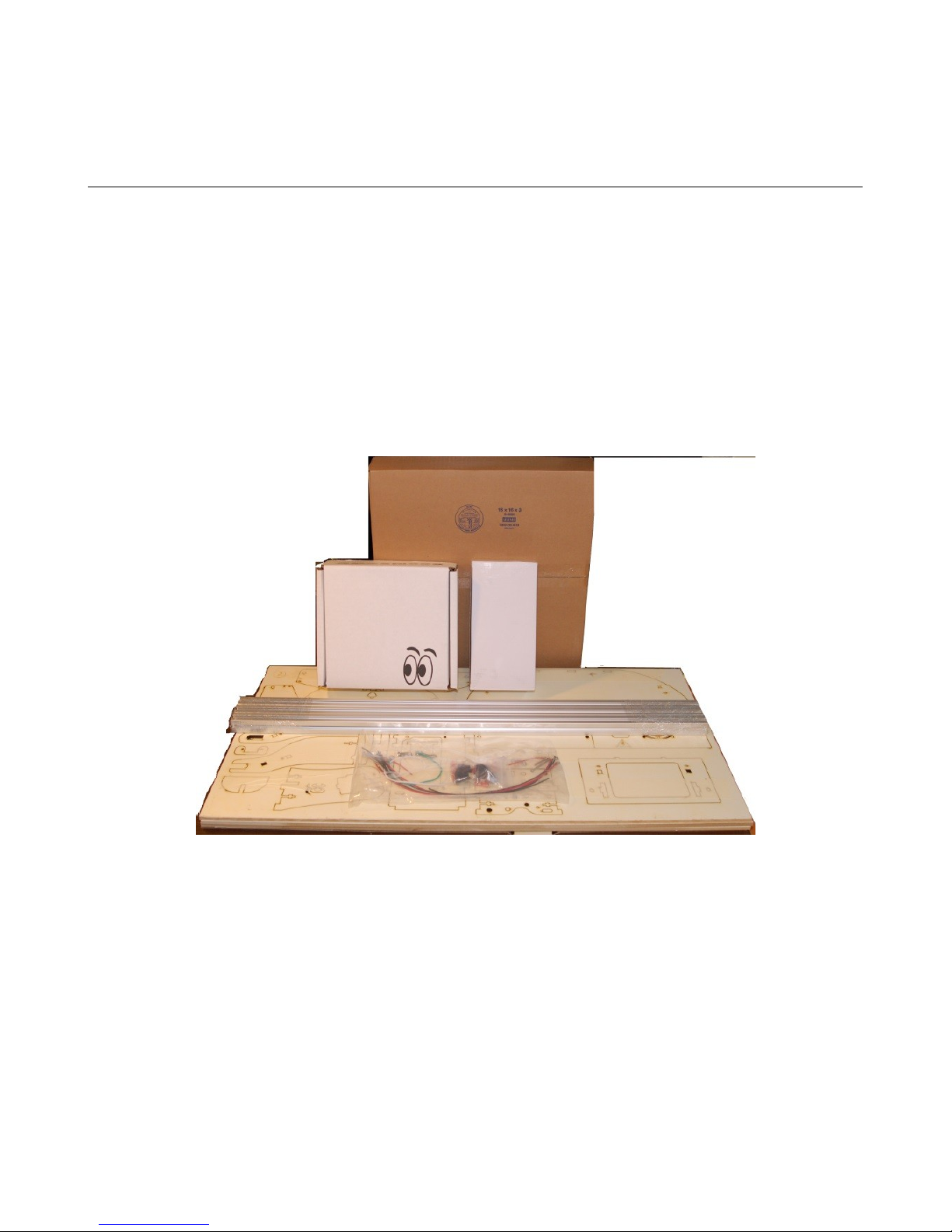
The Rostock MAX v2 kit shipping box should contain the following items:
•Four Melamine laser cut part sheets. (3 full, 1 partial) [84301]
•1 Smoked Acrylic Parts Package [84302]
•1 310mm x 3mm Borosilicate Glass Build Plate [26602]
•3 T-Slot Rail, 1” (25mm) square x 32” (812mm) long aluminum [68310]
•1 Power Supply 12V C, 30A Model LIHUA-360W [26733]
•1 Rostock MAX v2 Electronics and Hardware Pack, Rev3.
If you're planning on painting your Rostock MAX v2, especially the part edges, you would be
well served to carefully trace the outline of each part with a razor knife in order to cut the supporting
masking tape. This way you can retain the protective mask on the parts in order to make painting the
edges easier. Otherwise you'll have to re-apply a mask to avoid getting paint on the Melamine surfaces
of the parts.
2 – Visual Bill of Materials – 9
Shipping box contents.

Rostock MAX v2 Assembly Guide – 4thEd.
The Melamine parts are covered with a special cutting mask that prevents the laser cutting
operation from depositing cutting byproducts on the Melamine surface.
Leave this protective covering on the parts until you need them. This will save you the
laborious task of stripping all the masking tape off before the build. Note that if you want to paint your
Rostock MAX v2, you'll probably want to go ahead and strip the masking off of the parts now. If you
do so, please keep the parts grouped by sheet. When I specify parts for a task, I'll let you know what
sheet you can find them. If you don't keep them grouped together by sheet number after you paint
them, you'll spend more time looking for the parts I call out for a particular step.
Take special care when removing the laser cut parts from the sheets. Sometimes the laser
doesn't quite cut all the way through. If you find a part like this, you'll want to gently score the back
side of the sheet along the faint cut line and then press the part out from the front of the sheet. The
front and back of the sheet is easily identifiable – the front of the sheet will have very dark laser cut
lines with “flash” deposits to either side of the laser cut line. The back of the sheet will have much
fainter marks.
Note, the part sheets shown above will differ slightly from those that you have in your kit.
2 – Visual Bill of Materials – 10
Part Sheet #1
Part Sheet #2
Part Sheet #3
Part Sheet #4

Rostock MAX v2 Assembly Guide – 4thEd.
The white cardboard box will contain the laser cut Acrylic parts that are used in the build.
The Acrylic parts have a paper protective covering on them. Please leave that in place until
you're ready to install them.
The large cardboard box contains the hardware & electronic components required to build the
Rostock MAX v2. Many are in individual baggies, some are in heat-sealed bag “packs”. As you go
through the following Bill of Materials, please count and check off each item. This is important as you
don't want to be short a vital part during the build. It's better to find out before hand than being forced
to stop the assembly process due to a missing part. If you are missing any parts, please contact
[email protected] with the subject line of “Missing Parts!”.
2 – Visual Bill of Materials – 11
Acrylic parts.
Hardware & Electronic omponents
Rostock MAX v2 Assembly Guide – 4thEd.
For those that aren't sure how to identify the various screw types, Bolt epot has made
available some excellent references. I would recommend Fastener Basics
(http://www.boltdepot.com/fastener-information/Printable-Tools/Fastener-Basics.pdf) and their
Fastener Type Chart (http://www.boltdepot.com/fastener-information/Type-Chart.aspx).
Let's go ahead and do an inventory of the parts to ensure that you're not missing anything!
Please check off each item as you locate it. Where possible, I'll include the SeeMeCNC part number
enclosed in square brackets. Quantities are surrounded by parentheses.
Rostock MA v2 Hardware Pack #1, Rev3 [84381]
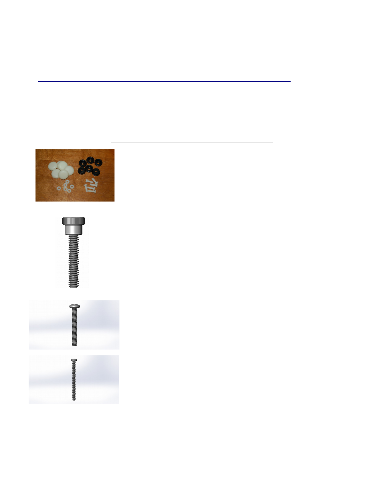
Rubber foot pack. Contains the following components:
[___] (6) #10-32, 5/8” Nylon Pan Head Screws [29998]
[___] (6) #10-32 Nylon Finish Nuts [30170]
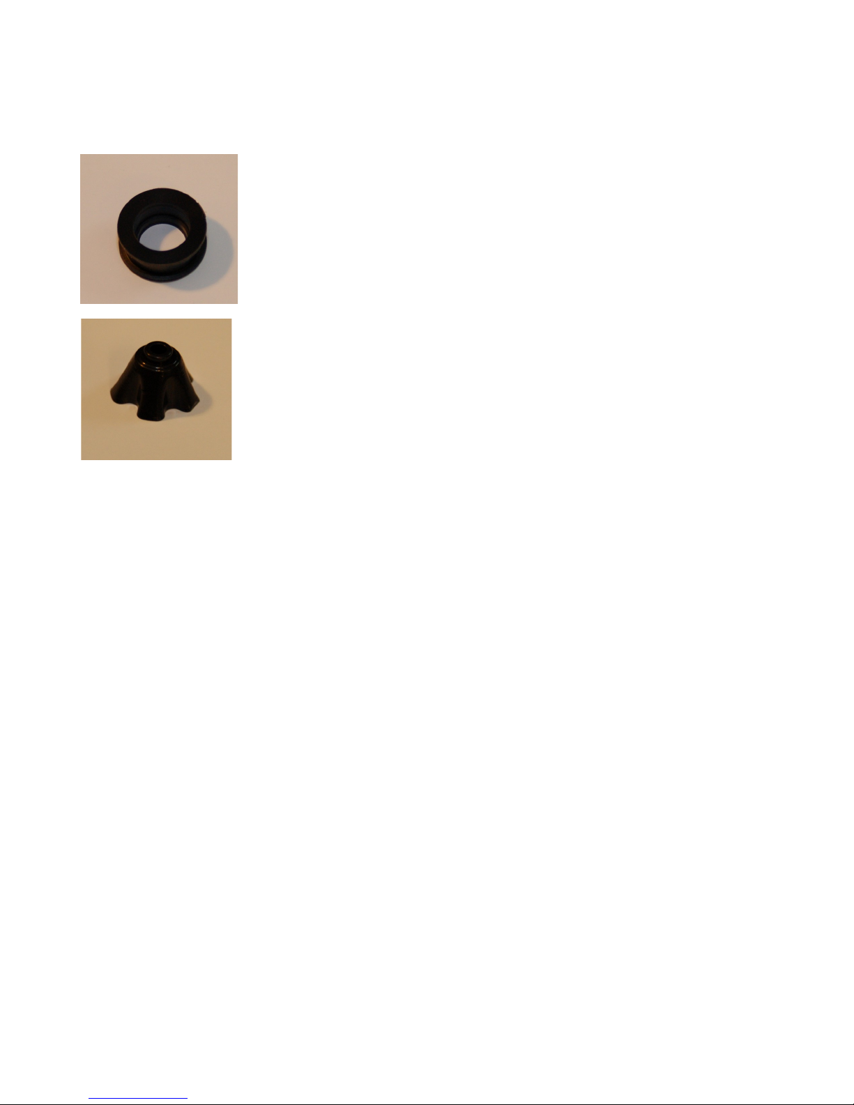
[___] (6) Injection molded feet (black) [17505]
[___] (6) Soft rubber “shoes” [44010]
[___] (9) #10-32, 3/4” Knurled Black Nylon Thumb Screws. [30172]
These are for the right & left base covers as well as the LC panel.
[___] (31) #6-32, 1” Phillips Pan Head Screws. Used for general
assembly. [30033]
[___] (9) #6-32, 1-3/4” Phillips Pan Head Stainless Steel screws. Used
for R4 idlers in the motor mounts as well as the hot end standoffs.
[30034]
2 – Visual Bill of Materials – 12
Rostock MAX v2 Assembly Guide – 4thEd.
[___] (42) #6-32 Stainless Steel Nylon Lock Nut – covers all #6-32
screws. [30164]
[___] (12) #6-32, 1/2” 18-8 Stainless Steel Flathead screw. Used inside
of base and top side plates, to retain acrylic panels and the three end-stop
triggering screws installed in the Cheapskate U-Joint mounts. [30135]
[___] (25) #¼-20, 1/2” Stainless Steel Button Head Cap Screws. Used for
tower mounting. [30419]
[___] (25) #¼-20 nut plates. Used for T-Slot mounting. [32005]
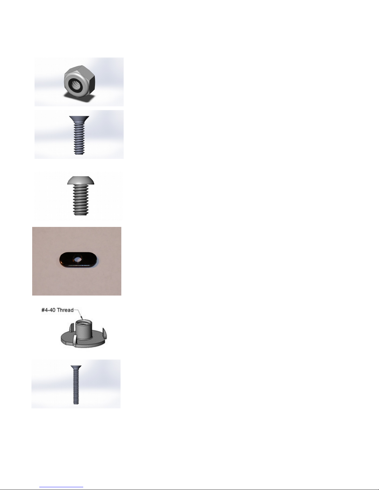
[___] (4) #4-40 T-Nuts. Used for RAMBo mounting. [30222]
[___] (4) #4-40, 3/4” Phillips Flat Head Machine screws. Used for
mounting the RAMBo Controller. [30236]
2 – Visual Bill of Materials – 13

Rostock MAX v2 Assembly Guide – 4thEd.
[___] (14) #2-56, 5/8” Pan Head Phillips Machine screws. Used for LC
mounting and end-stop switch mounting. [30650] (Combined Package)
[___] (14) 2-56 Finish Nuts. Used for LC mounting and end-stop
switch mounting. [30642] (Combined Package)
[___] (8) #4, 3/8” Phillips Pan Head Sheet Metal screws. Used for LC
sides and tower alignment stops. [30250]
[___] (12) M3x.5, 10mm Pan Head Machine screws. Used for
mounting the stepper motors. [30318]
[___] (18) #6 Stainless Steel Flat washers. Used on the 608 bearings
that go in the top & bottom T-Slot rails. [30450]
[___] (9) R4 (Small) Ball Bearings. Used in the belt idlers. [35008]
[___] (1) #10-32, 5/8” Socket Head Cap Screw. Used as a tap for the
#10-32 Nylon thumb screws. [29999]
2 – Visual Bill of Materials – 14

Rostock MAX v2 Assembly Guide – 4thEd.
Rostock MA v2 Hardware Pack #2, Rev 3 [84380]
[___] (12) Small Wire Ties. Used for wire management or Barbie
Handcuffs. Your call.
[___] (1) GT2 2mm pitch belt pulley pack. Includes six grub screws
and hex wrench. [39835]
[___] (6) Binder Clips. Used to hold the Borosilicate glass build plate to
the Onyx heated bed. [58761]
[___] (5) Plastic Bearing Rollers. Used for RAMBo mounting. [71505]
Qty shown in the photo is higher than qty shipped.
[___] (1) 15 Tooth Gear. Used for manually operating extruder motor.
[71566] This part is replaced by the part shown below and may not be
included in your kit.
[___] (1) Stepper Motor 5mm Shaft Handwheel. Used for manually
operating the extruder motor. [70710]
2 – Visual Bill of Materials – 15
Rostock MAX v2 Assembly Guide – 4thEd.
[___] (9) Pulley Bearing Cover for R4 Bearings. [39756]
[___] (18) R4 Bearing Standoffs [39757]
2 – Visual Bill of Materials – 16

Rostock MAX v2 Assembly Guide – 4thEd.
Rostock MA v2 Electronics and Hardware Pack #3, Rev 3 [84376]
[___] (1) RAMBo Electronic Control Board with screw terminals and
end stop wires. [26710]
[___] (1) USB Cable. [26708]
[___] (1) Onyx Heated Bed Sub-Assembly Pack [58770]
[___] (1) LC Smart Controller with S card, LC to RAMBo
Adapter Kit and 1 Soft Touch 5mm knob. [26720]
[___] (4) NEMA 17 Stepper Motors (4800gcm holding torque). Used for
three motion axes and extruder drive. [26501]
[___] (1) 25x25x10mm 12V C fan. Used to cool the PEEK section
on the hot end. [26309]
This fan is installed after you print the PEE fan shroud, as covered in
the User Guide.
[___] (1) 40x40x10mm 12V C fan. RAMBo cooling fan. [26177]
2 – Visual Bill of Materials – 17

Rostock MAX v2 Assembly Guide – 4thEd.
[___] 10 feet, 22ga, 4 conductor wire. Used to extend wiring for extruder
motor. [26722]
[___] 15 feet, 26ga, Black & Red wire. Used for hot end PEEK and part
fans. [26728, 26726] (Supplied as 30ft)
[___] 4 feet, 3/8” diameter Expandable Mesh Wire Loom (black). Used
to cover wiring & bowden tube from the top to the hot end platform.
Includes 3” of 5/16” heat shrink tubing. [26727, 26729]
[___] (3) 76” GT2 Timing Belts. [39910]
[___] (1) EZStruder Cold End Kit. Includes stepper motor mounting
hardware. [70780]
[___] (1) Hot End Kit. Includes hot end, heating resistors, thermistor,
PTFE sleeve for thermistor, PTC fittings and PTFE bowden tube.
[68394]
2 – Visual Bill of Materials – 18

Rostock MAX v2 Assembly Guide – 4thEd.
[___] (1) 30x30x10mm 12V C fan. Used for part cooling. [26171]
This fan is installed after you print the layer cooling fan shroud, as
covered in the User Guide.
[___] 8 feet, 18ga Red wire & 8 feet, 18ga Black wire. [26724, 26723]
[___] 15 feet, 26ga White wire. [26730]
2 – Visual Bill of Materials – 19

Rostock MAX v2 Assembly Guide – 4thEd.
Rostock MA v2 Hardware Pack #4, Rev 3 [84375]
[___] (2) 18awg, 2” Red [84310] Jumper for RAMBo terminal block.
[___] (2) 18awg, 2” Black [84311] Jumper for RAMBo terminal block.
[___] (1) 12awg, 14” Red [84312] PSU to RAMBo
[___] (1) 12awg, 14” Black [84313] PSU to RAMBo
[___] (1) 18awg, 8” Green [84314] IEC Connector to PSU
[___] (1) 18awg, 8” White [84315] IEC Connector to PSU
[___] (1) 18awg, 8” Black [84316] IEC Connector to PSU
[___] (1) 18awg, 3” Black [84317] Rocker switch to PSU
[___] (1) AC Connector Screw Mount IEC Plug Style [26180]
[___] (1) AC Power Cord with IEC termination. [26737]
[___] (2) #6-32 x 1” Pan Head Screws [30033] for IEC connector
[___] (4) #6-32 x 1.75” Pan Head Screws [30034] for 60mm fan
[___] (6) #6-32 Nylon Lock Nut [30164] Used with #6 hardware.
2 – Visual Bill of Materials – 20
Table of contents
Other SeeMeCNC 3D Printer manuals

SeeMeCNC
SeeMeCNC DropLit User manual

SeeMeCNC
SeeMeCNC Rostock Max v3 User manual

SeeMeCNC
SeeMeCNC Rostock MAX v2 User manual

SeeMeCNC
SeeMeCNC Rostock Max v3 User manual

SeeMeCNC
SeeMeCNC Artemis 300 User manual

SeeMeCNC
SeeMeCNC Rostock MAX v2 User manual

SeeMeCNC
SeeMeCNC Artemis User manual

SeeMeCNC
SeeMeCNC orion delta User manual

SeeMeCNC
SeeMeCNC Rostock MAX v2 User manual

SeeMeCNC
SeeMeCNC ERIS DELTA User manual


