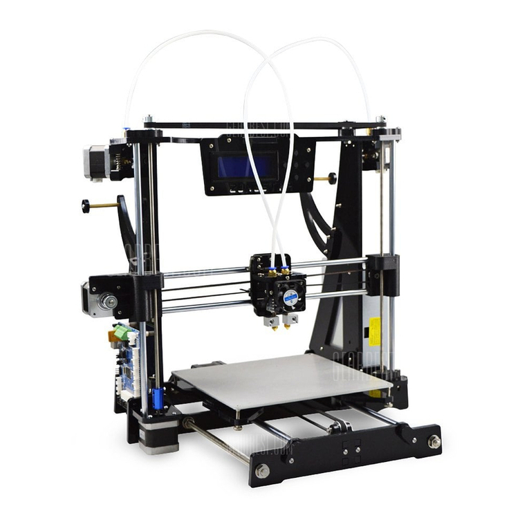
Zonestar Z8PM4 Pro User manual

Model: Z8PM3(4)Pro
User Guide

!! ATTENTION !!
Please put the printer away from the reach of kids.
Must be guided by adults when children are installed or used.
Take care when installation, to avoid electrical shock hazards.
Please keep well-ventilated condition! May produce toxic gases when
printer working.
Caution: Hot!
Hotend has high temperature even the printer stop working.
Caution: Hot!
Hotbed has high temperature even the printer stop working.
Please strictly follow the standard operation when installation.
Please make sure you have set the AC power select switch to the
correct position before power on.
The newest documents download link:
https://github.com/ZONESTAR3D/Z8P
2

Parts List
No.
Name
Check
No.
Name
Check
1
Base Module
□
8
Contol Panel
□
2
Extruders
(3 sets for M3 and 4 sets for M4)
□
9
Scews, lead screws fix blocks,
ENDSTOPs, Fittings,
PTFE Tubes, belt, cable tie, etc.
□
3
Z-axis Motor Modules (2 sets)
□
10
Filament Roll Bracket
□
4
Lead screw & Profiles
□
11
USB cable
□
5
Print head with bracket
M3 or M4 hotend
□
12
Tools
□
6
Z carrier left
□
13
SD card, Card Reader, Gift filament
□
7
Z carrier right
□
14
Power cord
□
14
1 32 5 6 7
9 131211
10
4
3
8

Parts
2x Z aluminum profiles, there are 4 taping hole on the end
There are 2 hole on the bottom side
These two holes on the bottom
when install
1x top aluminum profile, there are many hole on the front
1x X Profile, 2020-420mm, There are two big hole on the back
2x lead screws insert into the Z profie (They are put inside the Z aluminum profiles)
20* M4x18
8* M4x25
Z ENDSTOP
X Belt idler
PTFE Tube X Timing Belt
Z lead screw
fix blocks
4

Install Z axis Parts
M4x25 *4
M4x18 *4
2040V profiles
Install Z profiles to base
Z ENDSTOPs
Install Zmotor module to the Z profiles
Install Z ENDSTOPs module to the out side of the Z profiles
About 18mm
NOTE:
There are two hole
on the profile, let the
side with holes on the
bottom.
M4x18 *2
5

Install Z axis Parts
Install Z Carrier Install lead screws
Through the
copper nut
Fixed on the Coupling
of Z axis motor
Install Top profile
M4x25 *4
Top profile
Note:
Adjust the eccentric
cloumns let the carrier
hold the rail well and
move smoothly.
6

Install X axis Parts
M4x18 *4
X Profile
Install the X belt idler to the Z right
carrier, move it from right to left
Install the X profile to
the Z carrier
Install X belt idler and X profile
7

8
Install X axis Parts
Slide in the hotend from
the right to left
Layout the hotend cable
Keep the same heigth
Before fixed the X profile
Install X profile
Install print head (hotend assembly)

Move X belt idler to the right
after fixed the belt
Install X belt
Move X belt idler to the left
before fix the belt
Tigthen the X belt
Install the X belt
X Timing Belt
Hotend
(the hotend be hide in this picture)
Adjust the eccentric
cloumns, let the X
carrier hold the rail well
and move
smoothly

10
Install the other parts
Install the LCD screen on the right/bottom of printer
Z8-M3 is 3 sets and Z8-
M4 is 4 sets
Install the filament roll bracket to the top of the frame
Connect the extrusion feeder with the print head
by filament guide (PTFE tube)
NOTE: One of the channels is connected and
others closed by hotend clean tool when the
machine left factory. If you don't have
experience in using 3D printers, start with
single color.
Install Extrusion feeders to the top of the frame
M4x18 *6(8)
x 3 or 4
NOTE: Try to rotate the extruders a little when install
to keep a little clearance between the adjusting
screw and the indenter.
M4x18 *2

Debug the Z Movement system
Keep the lead screws parallel to the Z axis profiles as far as possible will help to obtain better
printing quality, please debug them refer to the following steps:
Step 1. Loosen all the screws a little that fixed the Z motors and T8 copper nut.
Step 2. Synchronous Rotate the couplings to move up the X axis to 1/2 height of the printer.
Step 3. Keep the lead screws parallel to the Z profiles, then tighten the screws that fixed the Z motor
and T8 copper nuts.
Step 4. Install the Z lead screws fix blocks on the top profile after done.
200mm
Loosen
a little
Put in
Fixed
Fixed

Adjust height of Z ENDSTOPs
Step 1: Adjust the 4 hand nuts under the hotbed, let the hotbed is parallel with bottom profile.
Step 2: Manual rotate the couplings on both of the Z axis motors , let the nozzle touched the hotbed.
Step 3: Move up the ENDSTOP, let its RED part touched the pulley of the Z carriers.
Step 4: Tighten the screws to fix the Z ENDSTOPs
1
2
4
3

!!ATTENTION!!
Take care when installation, to avoid electrical shock hazards!
Double check the wiring! WRONG WIRING MAY DAMAGED THE
ELECTRONIC DEVICE!
Set the 110V/220V swicth (on the side of power supply) to
correct position according to your city power voltage!
Put the motor wire to the grooves of profile and cover them by
plastic profile cover, and using cable tie to wrap the free wires.
Stop working immediately if the motor has abnormal vibration or
noise,, otherwise the driver modules may be damaged!
Make sure the hotend cooling fan is working when the nozzle
temperature is over 60 degree, otherwise check the wiring again.
DC-IN, HOTBED has lager operating current, please make sure
these wires contact well with the terminal.
13

14
About electronics parts
X MOTOR and X SW Y MOTOR and Y SW Z1 MOTOR and Z1 SW
Extrusion feeders
Bed leveling Sensor
Hotend
cooling FAN Z2 MOTOR and Z2 SW
Y MOTOR
See from left
NOTE: Y SW can be installed to
the right side too
DC power button
See from right
AC POWER
Switch
AC POWER
Connector
Control boarc
cooling FAN
110V/220V
Switch
Extruder
cooling FAN
Filament run out sensor (Optional)

Wiring Block

16
Layout the wires / cables
X Motor w/ SW cable
HOTEND Cable
ZL Motor w/ SW cable
Y Motor w/ SW cable
ZR Motor w/ SW cable
E1 Motor w/ SW cable
E2 Motor cable
EXT3 Motor cable
Hotbed cable
BOTTOM VIEW BACK VIEW
E1 Motor
E2 Motor cable
E3 Motor cable
FRODs wire
HOTEND Cable
X Motor w/ SW
cable
Put the motor wire
into the groove of
profile, and cover it by
the profile cover

Check before power on
17
Step 4: Manually move the hotend and hotbed to see if the movement is smooth, otherwise,
adjust the eccentric nut until the motor moves smoothly. Refer to the installation
procedure.
Step 3: Move the hotend and hotbed to their respective limit switch positions to check
whether the contact is good and there is a clear sound. Otherwise, please check the limit
switch and reassemble it.
Step 7: Manually rotate the z-axis screw rod to check whether the z-axis limit switch
contacts reliably.
Step 5: Check whether the X and Y-axis drive belt is firmly installed. If it is too loose,
please try to tighten it.
It is very important to check the machine before power on. It can eliminate the
trouble brought by some hardware to ensure the smooth printing!
Step 6: Check whether the screw rod is assembled in place and whether the screw is
tightened
Step 1:Please check if the X&Y axis timing pulley are fixed on the shaft of motor, and the
couplings are fixed on the shaft of the Z motors.
Step 2:Please check if the lead screws have been fixed on the shaft of coulping.

18
Power ON / Power OFF
Wait the LCD screen off
POWER OFF
“Switch
Power Off” on
LCD Screen
Turn OFF
AC Power Switch
Plug in power
cord
Turn ON
AC Power Switch
Push and hold DC
power button
until the LCD shows Logo
and release the DC
power button
POWER ON
!!ATTENTION!!
MAKE SURE THE AC VOLTAGE SELECT SWITH
HAS BEED SET TO THE CORRECT POSITION!!!
Power Off

LCD Menu and Operation
For details on the TFT-LCD menu, please refer to "LCD_DWIN Menu Description.pdf".
Printing from SD card
Prepare to printing
Setup the machine
Information of the machine
Control handle
Title bar
Menu bar
Status bar
19

Prepare to print - Level the hotbed
1. Power on the 3d printer and then do “Prepare>>Auto Home>>Home All” on control panel, wait the
hotend go to the HOME (origin) position.
2. Watch the nozzle, tighten the hand nuts under the bed to move down or loosen these nuts to move up
the bed (Fig 1), let the nozzle is higher than the bed about 1~2mm.
3. Do “Prepare>> Bed leveling>> Point 1(2/3/4)” on control panel(Fig 2), the nozzle will go to the
corners of the bed, adjust the hand nuts under the hotbed and let the nozzle almost touch the hotbed
(Fig 3). Continue to do the next point until all of the 4 corners has been leveled.
4. Repeat step 3 (recommend to do 3 rounds at least), until all of the four corners at the same height.
Fig 1 Fig 2 Fig 3
20
This manual suits for next models
1
Table of contents
Other Zonestar 3D Printer manuals

Zonestar
Zonestar P802QS User manual

Zonestar
Zonestar P802QS User manual

Zonestar
Zonestar Z5 Series User manual

Zonestar
Zonestar P802-STS User manual

Zonestar
Zonestar P802CR2 User manual

Zonestar
Zonestar Z6 User manual

Zonestar
Zonestar Z9 Series User manual
Zonestar
Zonestar Z8X User manual

Zonestar
Zonestar P802QS User manual