INTEGRA Metering RUBIN SONIC Smart User manual


Table of contents
Other INTEGRA Metering Measuring Instrument manuals
INTEGRA Metering
INTEGRA Metering AMTRON S3 User manual

INTEGRA Metering
INTEGRA Metering AMFLO SONIC UFA-280 Service manual
INTEGRA Metering
INTEGRA Metering AMFLO MAG Pro Service manual
INTEGRA Metering
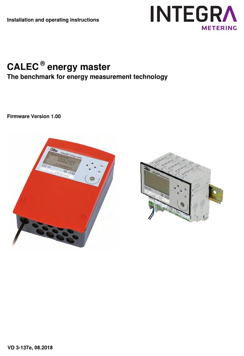
INTEGRA Metering aquastream LoRa User manual
INTEGRA Metering
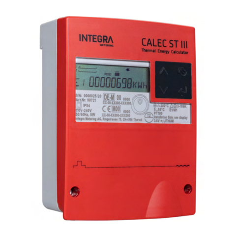
INTEGRA Metering CALEC energy master User manual
INTEGRA Metering
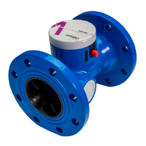
INTEGRA Metering CALEC ST III User manual
INTEGRA Metering
INTEGRA Metering RUBIN SONIC User manual
Popular Measuring Instrument manuals by other brands
Smart Tweezers
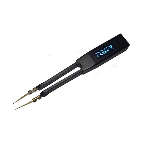
Smart Tweezers ST5-AS user manual
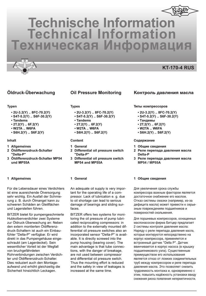
Bitzer
Bitzer KT-170-4 technical information
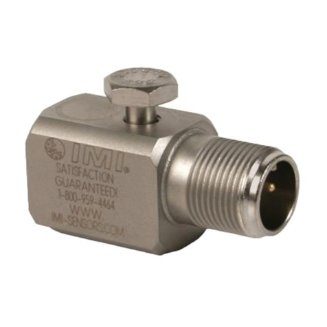
PCB Piezotronics
PCB Piezotronics IMI SENSORS 602D02 Installation and operating manual
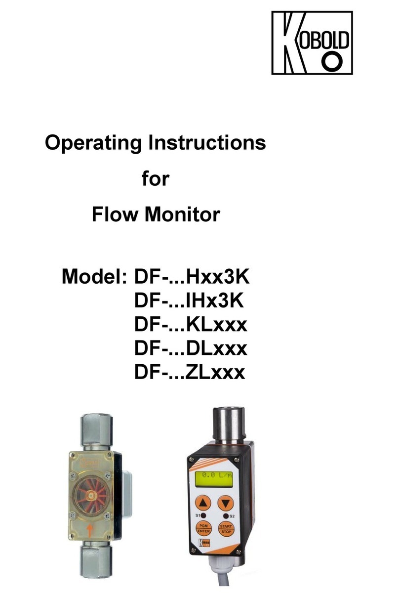
Kobold
Kobold DF H 3K Series operating instructions
Keysight
Keysight U1401B User's and service guide
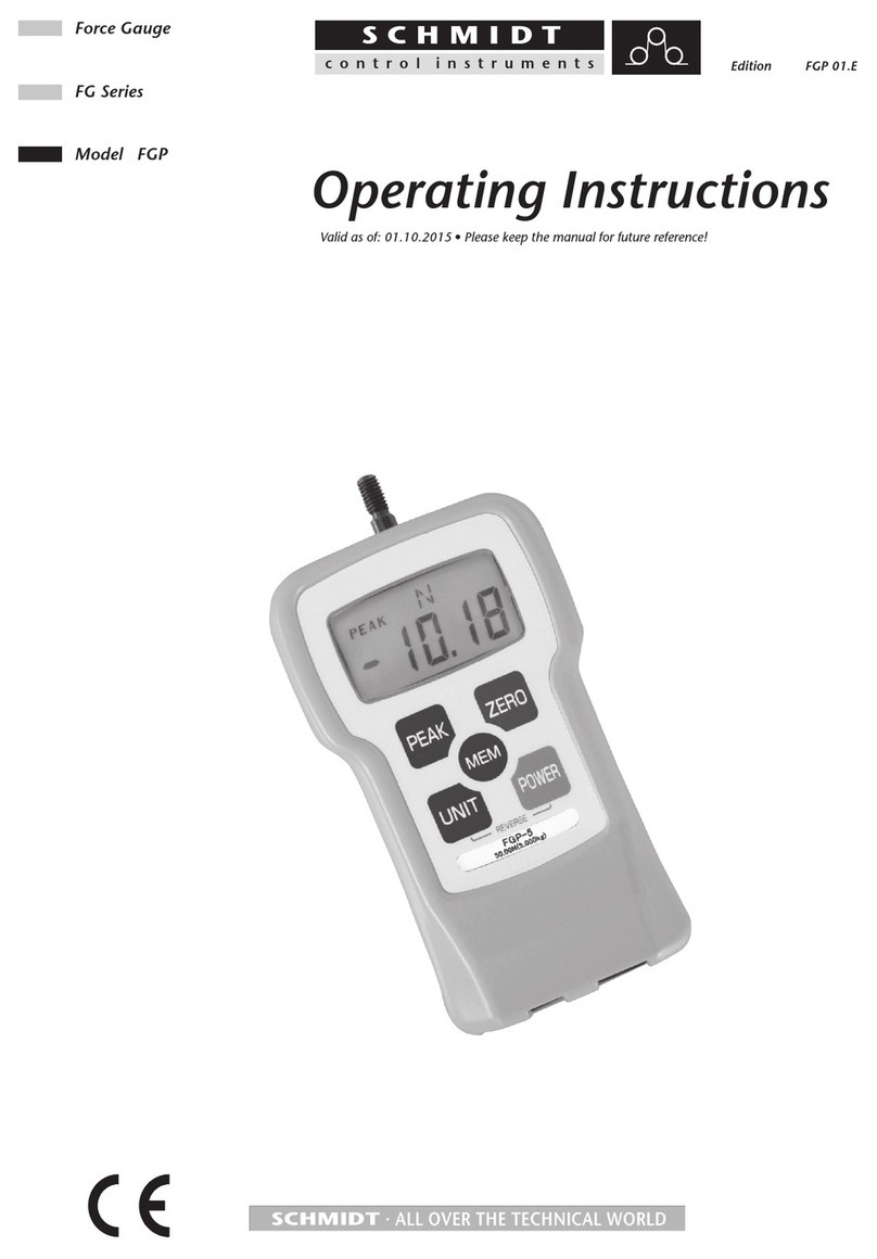
Schmidt
Schmidt FGP 01.E operating instructions
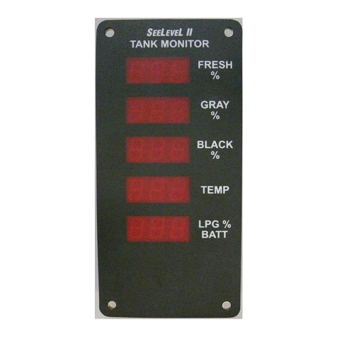
Garnet
Garnet SEELEVEL II 714 manual
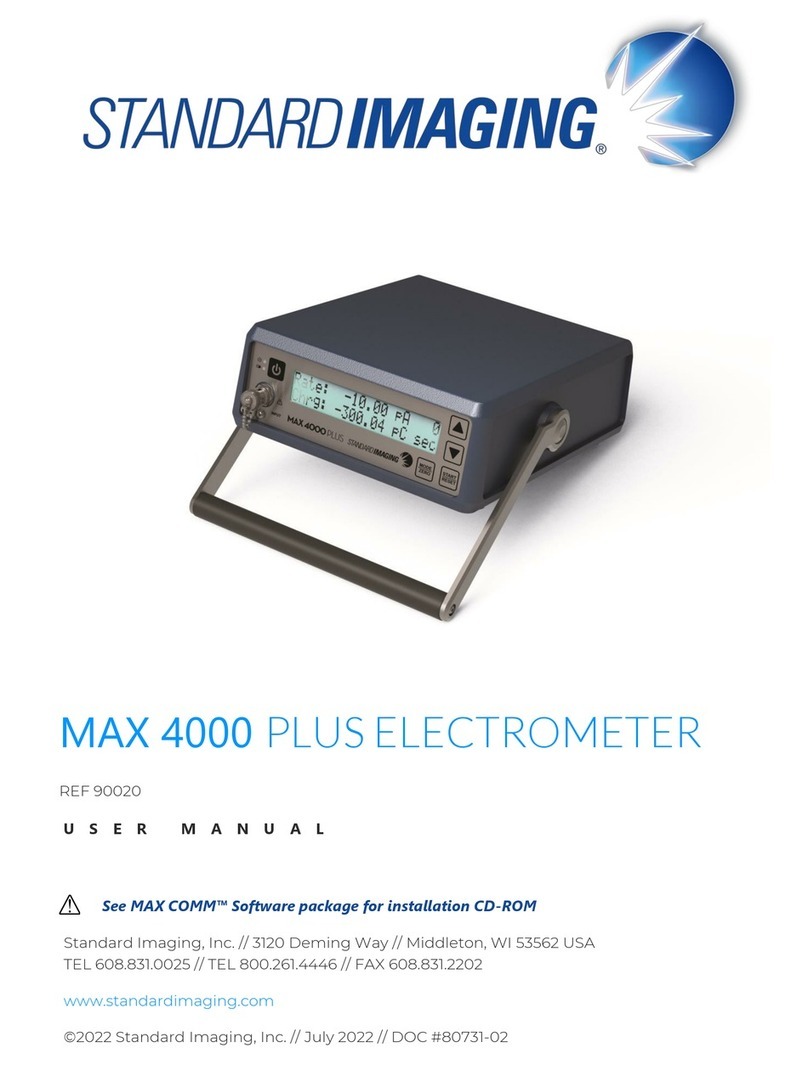
Standard Imaging
Standard Imaging MAX 4000 PLUS user manual
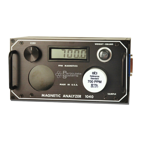
Particulate Systems
Particulate Systems MA-1040 Operator's manual
Excelitas Technologies
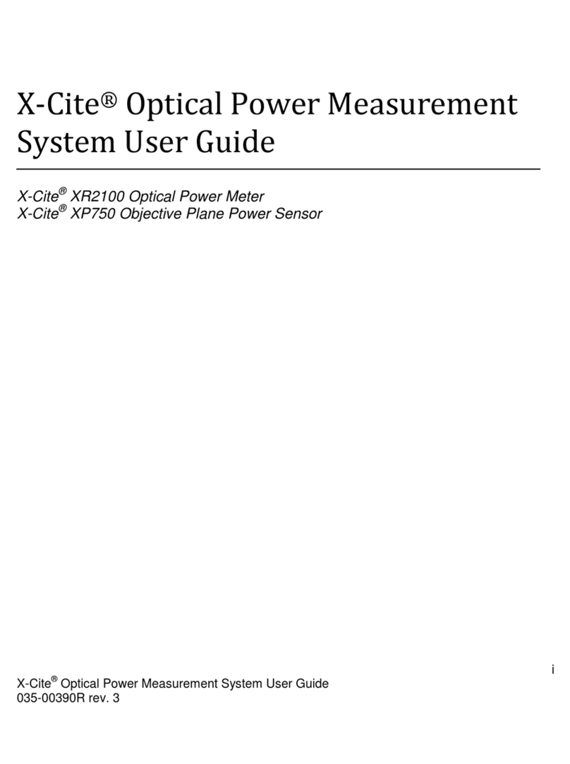
Excelitas Technologies X-Cite XR2100 user guide
Tektronix
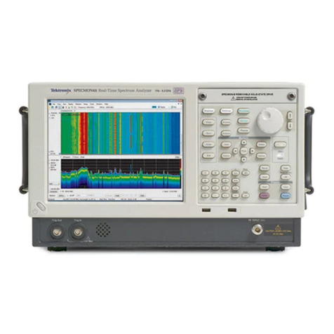
Tektronix SPECMON3 manual
Oxford PRECISION
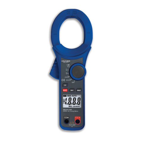
Oxford PRECISION OXD-516-1725D Operator's manual
