Intel Agilex User manual
Other Intel Microcontroller manuals

Intel
Intel Agilex User manual
Intel
Intel Agilex F Series User manual
Intel
Intel Arria 10 FPGA User manual

Intel
Intel Agilex User manual
Intel
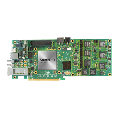
Intel Stratix 10 GX User manual

Intel
Intel 8XC196K Series User manual

Intel
Intel 80C196KB Series User manual
Intel
Intel GSU31 User manual

Intel
Intel Agilex User manual
Intel
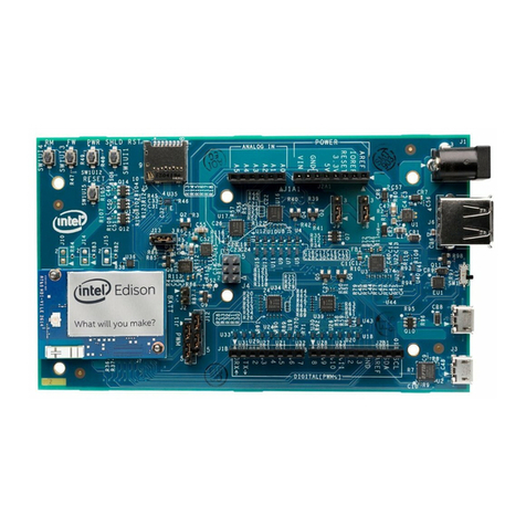
Intel Edison Kit for Arduino Installation instructions

Intel
Intel Agilex User manual
Intel
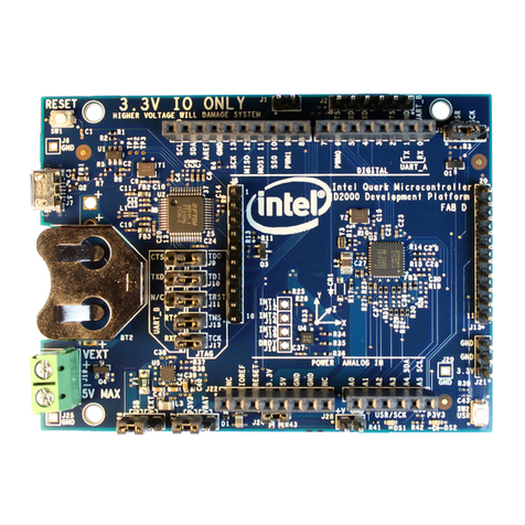
Intel Quark D2000 Guide
Intel
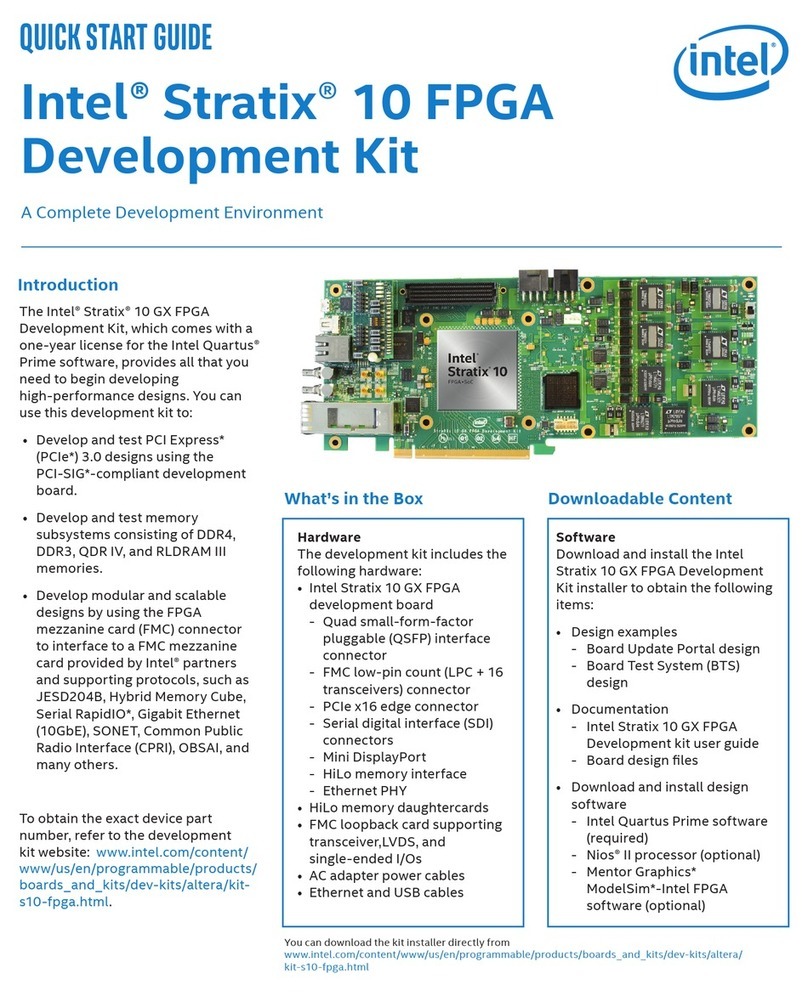
Intel Stratix 10 FPGA User manual
Intel
Intel Cyclone 10 GX User manual

Intel
Intel Agilex User manual

Intel
Intel EVI-EM2COMIF User manual

Intel
Intel 8XC196MC User manual

Intel
Intel Stratix 10 GX User manual
Intel
Intel Cyclone 10 GX FPGA User manual
Intel
Intel Galileo Operation instructions
Popular Microcontroller manuals by other brands

Novatek
Novatek NT6861 manual

Espressif Systems
Espressif Systems ESP8266 SDK AT Instruction Set

Nuvoton
Nuvoton ISD61S00 ChipCorder Design guide

STMicrolectronics
STMicrolectronics ST7 Assembler Linker user manual

Texas Instruments
Texas Instruments Chipcon CC2420DK user manual

Lantronix
Lantronix Intrinsyc Open-Q 865XR SOM user guide

NEC
NEC 78GK0S/K 1+ Series Application note

Mikroe
Mikroe SEMITECH N-PLC Click Application note

Cypress
Cypress CY4607 HX2VL quick start guide

DIGITAL-LOGIC
DIGITAL-LOGIC MICROSPACE manual

Texas Instruments
Texas Instruments TMS320F2837 D Series Workshop Guide and Lab Manual

CYPRES
CYPRES CY14NVSRAMKIT-001 user guide

