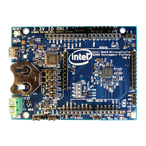
Intel® Quark™ SE Microcontroller C1000
June 2017 Platform Design Guide
Document Number: 334715-004EN 5
Figure 19. GPIO Pin Routing Topology ....................................................................................................................... 42
Figure 20. JTAG Topology................................................................................................................................................ 44
Figure 21. Analog Shielding Requirement................................................................................................................. 46
Figure 22. USB Topology .................................................................................................................................................. 48
Figure 23. USB Topology –Block Diagram ............................................................................................................... 48
Figure 24. Configuration for External VR ................................................................................................................... 52
Figure 25. Power Sequence for External Regulator .............................................................................................. 52
Figure 26. Power Timings for External Regulator .................................................................................................. 53
Figure 27. Power Delivered by an Internal 1.8V VR Only ................................................................................... 54
Figure 28. Power Sequence for Internal Regulator ............................................................................................... 55
Figure 29. GPIO Pin Termination Example (External Pull-Down Resistor).................................................. 57
Figure 30. Sensor Subsystem SPI Pin Termination Example............................................................................ 58
Figure 31. I2C Pin Termination Example..................................................................................................................... 58
Figure 32. I2C Pin Termination Example (External Pull-up Resistor) ............................................................. 59
Figure 33. UART Pin Termination Example............................................................................................................... 59
Figure 34. JTAG Pin Termination Example ............................................................................................................... 60
Figure 35. USB Pin Termination Example.................................................................................................................. 60
Tables
Table 1. Terminology.........................................................................................................................................................9
Table 2. Reference Documents .....................................................................................................................................9
Table 3. Stackup Details................................................................................................................................................ 13
Table 4. Alphabetical Ball Listing for BGA package .......................................................................................... 16
Table 5. Good Layout Practices ................................................................................................................................. 24
Table 6. I2C Interface Signals....................................................................................................................................... 25
Table 7. I2C Point-to-Point Platform Routing Guidelines ............................................................................... 26
Table 8. Capacitance Estimates for Calculating Rpu Values ......................................................................... 27
Table 9. PWM Interface Signals ................................................................................................................................. 28
Table 10. PWM Timing...................................................................................................................................................... 29
Table 11. Timer Period ..................................................................................................................................................... 30
Table 12. UART Signals .................................................................................................................................................... 31
Table 13. UART Point-to-Point Topology Platform Routing Guidelines .................................................... 32
Table 14. SPI Signals ......................................................................................................................................................... 34
Table 15. SPI Single Flash Platform Routing Guidelines ................................................................................... 34
Table 16. SPI Dual Flash Platform Routing Guidelines....................................................................................... 36
Table 17. SPI_CS Dual Flash Platform Routing Guidelines............................................................................... 37
Table 18. Clocking Signals .............................................................................................................................................. 39
Table 19. RTC Signals........................................................................................................................................................ 40
Table 20. RTC Point-to-Point Topology Platform Routing Guidelines ....................................................... 40
Table 21. 32Mhz Crystal Oscillator specification.................................................................................................. 40
Table 22. 32Khz Crystal Oscillator specification................................................................................................... 41
Table 23. GPIO Signals ..................................................................................................................................................... 42
Table 24. GPIO Pin Routing Guidelines..................................................................................................................... 43
