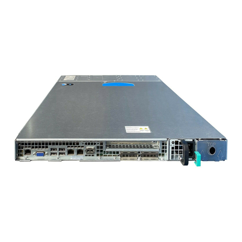
Intel® Server System R1000WF Product Family Technical Product Specification
6
3.3.13 Surge Immunity............................................................................................................................................................... 37
3.3.14 Power Recovery .............................................................................................................................................................. 37
3.3.15 Voltage Interruptions ................................................................................................................................................... 37
3.3.16 Protection Circuits ......................................................................................................................................................... 37
3.3.17 Power Supply Status LED ........................................................................................................................................... 38
3.4 DC Power Supply Input Specifications (iPC – AXX750DCCRPS) ................................................................ 38
3.4.1 DC Input Voltage ............................................................................................................................................................ 39
3.4.2 DC Input Fuse................................................................................................................................................................... 39
3.4.3 DC Inrush Current .......................................................................................................................................................... 39
3.4.4 DC Input under Voltage............................................................................................................................................... 39
3.4.5 DC Holdup Time and Dropout.................................................................................................................................. 39
3.4.6 DC Line Surge Voltages (Line Transients)............................................................................................................ 39
3.4.7 Susceptibility Requirements...................................................................................................................................... 40
3.4.8 Protection Circuits ......................................................................................................................................................... 40
3.5 Cold Redundancy Support......................................................................................................................................... 41
3.5.1 Powering on Cold Standby Supplies to Maintain Best Efficiency.............................................................. 42
3.5.2 Powering on Cold Standby Supplies during a Fault or Over Current Condition................................. 42
3.5.3 BMC Requirements........................................................................................................................................................ 42
3.5.4 Power Supply Turn on Function.............................................................................................................................. 42
3.6 Closed Loop System Throttling (CLST)................................................................................................................. 43
3.7 Smart Ride Through (SmaRT) ................................................................................................................................... 43
3.8 Server Board Power Connectors ............................................................................................................................. 43
3.8.1 Power Supply Module Card Edge Connector..................................................................................................... 43
3.8.2 Hot Swap Backplane Power Connector................................................................................................................ 44
3.8.3 Peripheral Power Connector ..................................................................................................................................... 44
4. Thermal Management ............................................................................................................................................. 45
4.1 Thermal Operation and Configuration Requirements.................................................................................... 46
4.1.1 Memory Slot Population Requirements ............................................................................................................... 46
4.2 Thermal Management Overview.............................................................................................................................. 48
4.2.1 Fan Speed Control......................................................................................................................................................... 48
4.3 System Fans ..................................................................................................................................................................... 52
4.4 Power Supply Module Fans ....................................................................................................................................... 54
4.5 FRUSDR Utility................................................................................................................................................................. 54
5. System Storage and Peripheral Drive Bay Overview........................................................................................ 55
5.1 Hot Swap Drive Carriers .............................................................................................................................................. 56
5.2 Hot Swap Backplane Support................................................................................................................................... 58
5.2.1 SGPIO Functionality ...................................................................................................................................................... 59
5.2.2 I2C Functionality.............................................................................................................................................................. 59
5.3 8 x 2.5” Drive SATA/SAS/NVMe* Combo Backplane....................................................................................... 59
5.4 4 x 3.5” Drive Hot-Swap Backplane........................................................................................................................ 61
6. Storage Controller Options Overview ................................................................................................................. 62
6.1 Onboard SATA Support .............................................................................................................................................. 62
