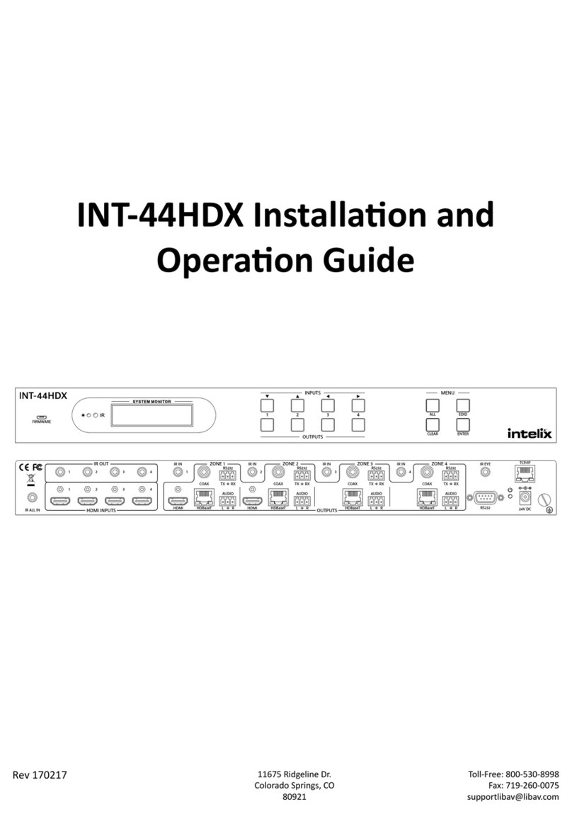
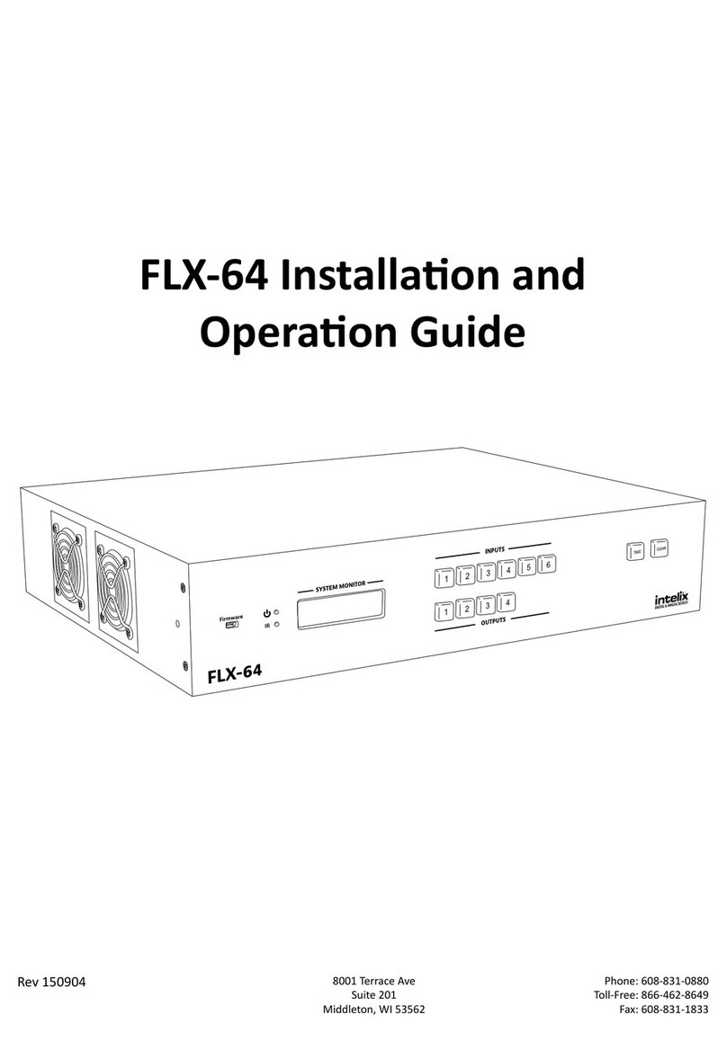
Intelix DIGI-HD-8X8 User manual

DIGI-HD-8X8
8 input by 8 output Matrix Switcher
This Manual is Optimized for Version 2.0 Matrices

Intelix DIGI-HD-8X8 Installation Manual
2 www.intelix.com
Table of Contents
Overview............................................................................................. 4
Installation.......................................................................................... 5
Operation............................................................................................ 8
Technical Specifications ...................................................................14
Appendix A: Communication Protocol .............................................15
Appendix B: Troubleshooting in Dual UTP Mode...........................31
Appendix C: Troubleshooting in Single UTP Mode........................ 33
Appendix D: Touch Screen Tour ..................................................... 35
Appendix E: Touch Screen How-To................................................ 39
Appendix F: Web Browser Control ...................................................41
Warranty ........................................................................................... 42
Contact Information………………………………………………… 44
Copyright 2011 Intelix LLC.
Design with Intelligence
Rev.1103

Intelix DIGI-HD-8X8 Installation Manual
www.intelix.com 3
Important Safety Instructions
Please completely read and verify you understand all instructions in this manual before operating this equipment.
Keep these instructions in a safe, accessible place for future reference.
Heed all warnings.
Follow all instructions.
Do not use this apparatus near water.
Clean only with a dry cloth.
Do not install near any heat sources such as radiators, heat registers, stoves, or other apparatus (including amplifiers) that
produce heat.
Use only accessories specified or recommended by Intelix.
Explanation of graphical symbols:
oLightning bolt/flash symbol: the lightning bolt/flash and arrowhead within an equilateral
triangle symbol is intended to alert the user to the presence of uninsulated “dangerous
voltage” within the product enclosure which may be of sufficient magnitude to constitute a
risk of shock to a person or persons.
oExclamation point symbol: the exclamation point within an equilateral triangle symbol is
intended to alert the user to the presence of important operating and maintenance
(servicing) instructions tin the literature accompanying the product.
WARNING: TO REDUCE THE RISK OF FIRE OR ELECTRIC SHOCK, DO NOT EXPOSE THIS
APPARATUS TO RAIN OR MOISTURE AND OBJECTS FILLED WITH LIQUIDS, SUCH AS VASES,
SHOULD NOT BE PLACED ON THIS APPARATUS.
Use the mains plug to disconnect the apparatus from the mains.
THE MAINS PLUG OF THE POWER SUPPLY CORD MUST REMAIN READILY ACCESSIBLE.
Do not defeat the safety purpose polarized or grounding-type plug. A polarized plug has two blades with one wider than
the other. A grounding-type plug has two blades and a third grounding prong. The wide blade or the third prong is
provided for your safety. If the provided plug does not fit into your outlet, consult an electrician for replacement of your
obsolete outlet. Caution! To reduce the risk of electrical shock, grounding of the center pin of this plug must be
maintained.
Protect the power cord from being walked on or pinched particularly at the plugs, convenience receptacles, and the point
where they exit from the apparatus.
Do not block the air ventilation openings. Only mount the equipment per Intelix’s instructions.
Use only with the cart, stand, tripod, bracket, table, or rack specified by Intelix or sold with the
equipment. When/if a cart is used, use caution when moving the cart/equipment combination to
avoid injury from tip-over.
Unplug this apparatus during lightning storms or when unused for long periods of time.
Caution! Shock Hazard. Do not open the unit. Refer to qualified service personnel. Servicing is required when the
apparatus has been damaged in any way, such as power-supply cord or plug is damaged, liquid has been spilled or
objects have fallen into the apparatus, the apparatus has been exposed to rain or moisture, does not operate normally, or
has been dropped.
Refer all servicing to qualified service personnel. Servicing is required when the apparatus has been damaged in any
way, such as the power-supply cord or plug is damaged, liquid has been spilled or objects have fallen into the apparatus,
the apparatus has been exposed to rain or moisture, does not operate normally, or has been dropped.

Intelix DIGI-HD-8X8 Installation Manual
4 www.intelix.com
Overview
The Intelix DIGI-HD-8X8 combines professional-grade performance with
comprehensive control options, providing an easy-to-use, flexible, and powerful
solution for high-definition audio/video distribution applications. A true matrix
switcher, the DIGI-HD-8X8 features eight HDMI inputs, eight HDMI outputs and
eight twisted pair extender outputs. The matrix supports 1080p high-definition video
and is HDMI 1.3/HDCP compliant. Switching is controlled via a diagnostic front panel
touch screen or remotely via RS232, IR, or Ethernet.
In addition, the DIGI-HD-8X8 features eight pass-through IR channels which distribute
remote IR commands from in-room controllers, through compatible Intelix twisted pair
extenders, up to 150 feet over twisted pair cable, and out of the matrix, allowing
complete control of remote sources from the destination.
Design with Intelix and Design with Intelligence.
DIGI-HD-8X8 Package Contents
DIGI-HD-8X8 matrix switcher
12 VDC power supply
19” rack-mounting ears
Remote control
IR receiver
Manual

Intelix DIGI-HD-8X8 Installation Manual
www.intelix.com 5
Installation
To install the Intelix DIGI-HD-8X8 matrix switcher, please perform the following steps.
1. If mounting in a 19” audio/video rack, attach the 19” rack ears to the DIGI-HD-8X8. The
DIGI-HD-8X8 requires 4 rack units of spacing.
2. Power-off the source and destination audio and video devices.
3. Connect the input sources to the DIGI-HD-8X8 using high-quality HDMI cables.
4. Connect the output destinations to the DIGI-HD-8X8 using high-quality HDMI cables.
5. For long distance destinations, connect twisted pair cable to the DIGI-HD-8X8 (twisted pair
receivers sold separately).
Note: All connecting audio-visual equipment must be powered off.

Intelix DIGI-HD-8X8 Installation Manual
6 www.intelix.com
Ventilation when Rack Mounting
At least 2 inches of free air space is required on both sides of the
DIGI-HD-8X8 for proper side ventilation.
Ensure there are no closeable doors on the rack that might seal the
DIGI-HD-8X8 from a steady supply of cool air.
Avoid mounting the DIGI-HD-8X8 near a power amplifier or any
other source of significant heat.
It is recommended that you leave an empty rack space above and
below the DIGI-HD-8X8 for additional cooling.
Note: The DIGI-HD-8X8 supports either
single or double twisted pair extenders; both
styles may not be used simultaneously.

Intelix DIGI-HD-8X8 Installation Manual
www.intelix.com 7
Recommended Twisted Pair Receivers
Signals Twisted Pair Cables
Required
DIGI-HD-UHR2-R HDMI 1
DIGI-HD-IR2-R HDMI and IR 2
Recommended Twisted Pair Distances
1080p 1080i 720p 480i/p
Cat 6 (low-skew) 150’ 300’ 300’ 350’
Cat 6 110’ 220’ 220’ 220’
Cat 5e 100’ 200’ 200’ 200’
6. Connect the included 12 VDC power supply to the DIGI-HD-8X8.
7. If controlling remotely, connect RS232, Ethernet, or IR control cables.
8. Power-on the DIGI-HD-8X8.
9. Power-on the source and destination audio and video devices.
Signal Mode Settings: HDshāk Inside
The DIGI-HD-8X8 features HDshāk processing, which is activated and toggled
through the signal mode DIP switches on the rear of the unit.
To change the signal mode:
1. Power off the DIGI-HD-8X8.
2. Set the DIP switches to the desired setting.
3. Power on the DIGI-HD-8X8.
Note: The DIGI-HD-8X8 supports dual and single twisted pair receivers.
Different modes of operation are toggled through the rear panel DIP switches, as
shown on the following page. The DIGI-HD-8X8 must be in either single or dual
twisted pair mode—both modes cannot operate simultaneously.

Intelix DIGI-HD-8X8 Installation Manual
8 www.intelix.com
DIP
1 DIP
2 DIP
3 DIP
4 EDID Function
off on on off Dual Twisted Pair Auto-mix Mode
The matrix mixes the EDID data of all destinations which choose the same source.
This data is then transmitted by the matrix to the source device.
off on off off Dual Twisted Pair Copy Mode
EDID data is copied from the outputs and transmitted to the inputs.
on off off off Dual Twisted Pair HDMI 1.2 with stereo audio
The matrix is preset with EDID data for HDMI 1.2 video and stereo audio.
on off on off Dual Twisted Pair HDMI 1.2 with 5.1 audio
The matrix is preset with EDID data for HDMI 1.2 1080p video and 5.1 audio.
on on off off
Dual Twisted Pair HDMI 1.3 with stereo audio
The matrix is preset with EDID data for HDMI 1.3 1080p video and stereo audio.
on on on off
Dual Twisted Pair HDMI 1.3 with 5.1 audio
The matrix is preset with EDID data for HDMI 1.3 1080p video and 5.1 audio.
off on off on Single Twisted Pair Copy Mode
EDID data is copied from the outputs and transmitted to the inputs.
on off off on Single Twisted Pair HDMI 1.2 with stereo audio
The matrix is preset with EDID data for HDMI 1.2 video and stereo audio.
on off on on Single Twisted Pair HDMI 1.2 with 5.1 audio
The matrix is preset with EDID data for HDMI 1.2 1080p video and 5.1 audio.
on on off On
Single Twisted Pair HDMI 1.3 with stereo audio
The matrix is preset with EDID data for HDMI 1.3 1080p video and stereo audio.
on on on on Single Twisted Pair HDMI 1.3 with 5.1 audio
The matrix is preset with EDID data for HDMI 1.3 1080p video and 5.1 audio.
Operation
To operate the Intelix DIGI-HD-8X8 matrix switcher, please perform the following steps.
Front Panel Control Basics
The DIGI-HD-8X8 features a front panel touch screen for programming and control.
Note: The DIGI-HD-8X8 features on-board memory. Settings are stored
when exiting the Utilities screen and restored during power on.

Intelix DIGI-HD-8X8 Installation Manual
www.intelix.com 9
1. Determine if the DIGI-HD-8X8 front panel is locked. If the panel is locked, the System is
Locked screen will appear. The user password must be entered.
2. Determine which output or preset you wish to change.
3. If changing a preset (scene), select the Preset button. Select the desired preset.
4. If changing output routing, select Room View or Matrix View. Select the desired output and
source.
Touch Screen Flow Diagram
*n
Note: The DIGI-HD-8X8 features two levels of
security: one for the contractor (admin
password) and one for the owner (user
password). The user password locks the system,
the admin password locks the programming.
Default Passwords
User: 1234
Admin: HDMI
Touch Screen Flow Diagram

Intelix DIGI-HD-8X8 Installation Manual
10 www.intelix.com
Included Remote Control
The DIGI-HD-8X8 includes a multi-function wireless remote
control for switching inputs to the various outputs.
IR Remote Control
The DIGI-HD-8X8 supports remote control through a front panel IR sensor and a rear panel 1/8”
(3.5 mm) input jack.
1. If controlling the DIGI-HD-8X8 through the 1/8” (3.5 mm) input jack on the rear panel,
connect the included IR receiver (eye) directly to the matrix.
2. If controlling the DIGI-HD-8X8 through the IR sensor on the front panel, place an IR
emitter directly over the front panel sensor.
RS232 Remote Control
The DIGI-HD-8X8 supports remote control through a rear panel RS232 control port.
IR Emitter Mounting Tips
Surrounding electrical equipment may be producing high levels of IR
noise. Plasma TVs and compact fluorescent lights are known
polluters. Shield the outside of the emitter and the hardware’s IR
window with electrical tape.
Verify the emitter is directly on the hardware’s IR window and
directly over the IR sensor. Operation may be intermittent if the
emitter is too far away from the sensor.
Clean the DIGI-HD-8X8 IR sensor window with an alcohol-based
cleaner before applying the emitter to guarantee adhesion.
Should the emitter not adhere to the DIGI-HD-8X8 sensor window,
apply a small drop of glue to the adhesion pad on the emitter and re-
apply.
Note: Operation of the rear panel IR input will disable the front panel IR
sensor. Third-party IR devices are not compatible with the rear panel IR
input.
Communicating Directly to the Matrix
When communicating directly to the matrix, the remote
control provides scrolling for each destination. Buttons 1-8
represent destinations; the back arrow button selects the
previous source and the forward arrow button selects the
next source.
Communicating to the Matrix through Extenders
When communicating to the matrix remotely, the remote
control provides independent source selection within the
zone. Buttons S1-S8 represent inputs; the back arrow
button jumps to the corresponding input source. The
forward arrow button is deactivated in this mode.

Intelix DIGI-HD-8X8 Installation Manual
www.intelix.com 11
1. If controlling the DIGI-HD-8X8 through the RS232 control port on the rear panel, connect a
straight-through serial cable directly to the matrix.
115200 baud rate (default baud rate)
8 data bits
1 stop bit
No handshake
Ethernet Remote Control
The DIGI-HD-8X8 supports remote control through a rear panel Ethernet control port. The
matrix accepts control messages when integrated to a local area network (LAN).
1. If controlling the DIGI-HD-8X8 through the Ethernet control port on the rear panel, connect
an Ethernet cable directly to the matrix.
2. Connect the opposite end of the Ethernet cable to a LAN port. Within 10 seconds of
connecting the DIGI-HD-8X8 to the LAN, the yellow LED on the matrix’s Ethernet port
will stop blinking and the green LED will blink intermittently.
Note: The DIGI-HD-8X8 will automatically be assigned an IP address
when connected to a DHCP-enabled network. By default, DHCP is is
enabled.
Connection Troubleshooting: If the matrix does not respond with a green
LED, please follow the steps below:
-Verify the LAN has DHCP support and the matrix is in DHCP
mode.
-Verify the LAN port is active.
-Verify the Ethernet cable has the correct wiring (568A or B,
straight-through) and the RJ45 connector is properly terminated.
-Verify the connecting computer is configured to use DHCP.
-Verify the connecting computer successfully connects to the
internet. If it does not, contact the network administrator for
assistance.
Note: For RS232 programming and command information, see Appendix A.

Intelix DIGI-HD-8X8 Installation Manual
12 www.intelix.com
IR Twisted Pair Pass-Through
When used with compatible Intelix receivers (DIGI-HD-IR2-R), the DIGI-HD-8X8 supports
eight pass-through IR channels which distribute remote IR commands from in-room controllers,
up to 300 feet over twisted pair cable, and out of the matrix.
1. Determine which devices you wish to control via the IR pass-through outputs.
2. Connect an IR emitter to the desired IR transmit output port.
3. Repeat for up to eight devices.
4. All of the remote receive baluns transmit IR commands from the included remote control,
thereby allowing remote control of the matrix itself.
5. Verify that IR pass-through is enabled in the front panel LCD Utilities screen.
Note: Optionally, IR commands for the matrix may be transmitted from a
remote DIGI-HD-IR2.
Note: By default, IR transmit output one corresponds to HDMI input one, IR
transmit output two corresponds to HDMI input two, IR transmit output three
corresponds to HDMI input three, etc. Therefore, the IR output port will
control the source connected to the HDMI in
p
ut.
Note: For Ethernet programming and command information, see Appendix
A.
Note: To test transmission, connect a controller (software or hardware that
generates a serial message) and send the command F1h 02h 00h 00h 00h to
the matrix’s IP address and to port 8001 on the network. This is an “are
you there” or ping command.

Intelix DIGI-HD-8X8 Installation Manual
www.intelix.com 13

Intelix DIGI-HD-8X8 Installation Manual
14 www.intelix.com
Technical Specifications
Vertical Frequency Range .....................................................................24 - 60 Hz
Output Video ....................................................................... HDMI 1.2/HDMI 1.3
Signaling Rate.................................................................. 2.25 gigabits per second
Input DDC Signal ....................................................................5.0 volts p-p (TTL)
Input Video Signal.....................................................................0.5 – 1.0 volts p-p
Video Amplifier Bandwidth ................................................................... 255 MHz
Input Connectors.............................................Eight (8) HDMI type A connectors
Output Connectors......... Eight (8) HDMI type A connectors with locking screws
Eight (8) dual twisted pair connectors
Supported Video Resolutions ............480i, 480p, 576i, 576p, 720p, 1080i, 1080p
8, 10, 12 bits per channel
Supported Audio........ Dolby TrueHD 7.1, Dolby TrueHD 5.1, Dolby Digital 5.1
DTS-HD Master Audio 7.1, DTS-HD Master Audio 5.1,
DTS 5.1, PCM 2.0, PCM 5.1
Status Indicators.......................................................................... Front panel LCD
Operating Temperature Range.................................................-41 to 95 degrees F
-5 to 35 degrees C
Operating Humidity Range............................................5 to 90% non-condensing
Included Accessories ............................................ One (1) 12 VDC power supply
Two (2) 19” rack mounting ears
One (1) remote control
One (1) IR receiver
Eight (8) IR emitters
Four (4) shelf feet
Control......................................................... Front panel, RS232, IR and Ethernet
Dimensions (WxHxD) ....................................................... 17.25” x 7.00” x 8.25”
4 RU
Enclosure ............................................................................................ Black metal
Max Power Consumption ......................................................................... 60 watts
Power.........................................................................................................12V 5A
Regulatory .............................................................................................CE, RoHS
Compatible Intelix Twisted Pair Receivers ............................ DIGI-HD-UHR2-R
DIGI-HD-IR2-R
Shipping Weight ........................................................................................... 12 lbs
Intelix Part Number ........................................................................DIGI-HD-8X8
Warranty ..................................................................................................... 2 years

Intelix DIGI-HD-8X8 Installation Manual
www.intelix.com 15
Appendix A: Communication Protocol
Serial Message Protocol Overview—Simple escaped—Version
The Intelix Simple escaped version serial message protocol can be related to the data link layer
(layer 2) of the ISO layered communications model. It is a connectionless datagram messaging
protocol.
Serial Message Fields
All serial messages, whether they are transmitted to or from an Intelix device, use the same
message format. Each message contains several distinct fields. All values are transmitted in
hexadecimal format e.g. 0Ah.
Serial Message Fields; Version 3
Send Message Frame (Simple escaped Protocol)
Protocol Start Length Data
1 byte 1 byte 0<n<255 bytes
F1h ##h
The first field of a message is always the START byte. The second field is a 1-byte length. The
value of the length field is the number of bytes in the third field, the data field. The third field,
the data field, holds the parameters of the message e.g. Message Class, Message ID, Parameters,
etc.
Hexadecimal Transmission
The Intelix Matrix Mixer must receive all messages in hexadecimal number code. If messages
are transmitted in decimal or ASCII codes, they will fail to work. Hexadecimal is a base 16
number code that uses numerals 0-10 and letters A, B, C, D, E, F. In this document hex numbers
are represented in the form “xxh”, where xx are the two hex characters.
ASCII values
When you send commands to an Intelix Device, there is one and only one case when you use
ASCII codes. That case is when you send names. Whenever a name field appears in an example
in this manual, the example is enclosed in quotation marks. Any other use of ASCII values will
cause the command to fail. For example the command Set Matrix Mixer Name uses as an
example name field “Emmanuel Lutheran Church”. The quotes indicate that this data should be
sent as ASCII values. To do this use an ASCII table to obtain the hex value for each character,
and transmit these values. Do NOT transmit the quotation marks unless you want the quotation
marks included in the Name data written to the device. The Quotation marks in the examples are
ASCII text delimiters for the user of this manual.
Byte Escape Sequence
The Simple escaped version message protocol used an “escape byte” sequence to insure
unambiguous recognition of protocol control bytes (F0 – FFh). If a byte in the length, data, or
checksum fields falls within the range F0h through FFh inclusive, an escape sequence is used to
transmit the value. The value is translated by sending two bytes: the ESCAPE byte (F0h) itself,
followed by the difference between the value and the ESCAPE byte. Example; If value =>
ESCAPE, then value = (value - ESCAPE). These two bytes are transmitted instead of the single,
large-value byte. The receiving device converts the two bytes back into the original single byte
value through simple addition. These operations do not affect the values of the length or
checksum fields. i.e., The Escape byte algorithm is applied to the message string last on
transmission and first upon receipt (skipping the start byte).
In the following example, the data field of a message is (02h, 03h, 03h, 06h, FFh). The byte FFh
must be “escaped” into the ESCAPE byte (F0h) followed by the difference between FFh and
ESCAPE (FFh – F0h = 0Fh). The bytes actually transmitted are: (02h, 03h, 03h, 06h, F0h, 0Fh).
Since the second byte of an escape sequence must fall within the range 00h through 0Fh

Intelix DIGI-HD-8X8 Installation Manual
16 www.intelix.com
inclusive, any second byte outside of that range indicates that a transmission error has occurred,
and the Ack byte will not be sent.
Non-escaped example:
Serial_Start Length Class Message
ID Input Output Target
Value
F1h 05h 02 03h 03h 02h F6h
Escaped example:
Serial_Start Length Class Message
ID Input Output Target
Value
F1h 05h 02 03h 03h 02h F0h 06h
Reserved Bytes
The following table lists the bytes which have special meaning in all Intelix Serial Message
protocols:
FF Reserved
FE Error
FD ACK (Version 4 sequence bit 1)
FC Version 3 ACK (Version 4 sequence bit 0)
FB Start byte (Version 2 protocol)
FA Start byte (Version 3 protocol)
F9 Start byte (Version 3 escaped protocol)
F8 Start byte (Version 4 protocol)
F7 Reserved
F6 Reserved
F5 Reserved
F4 Reserved
F3 Reserved
F2 Reserved
F1 Start bytes (simple escaped protocol)
F0 Escape byte
Simple Escaped RS232 Com Port Communication Details
115200 baud
8 data bits
1 stop bit
No parity
DCE unit (straight through serial cable)
Command Protocol
The DIGI-HD-8X8 protocol will allow the user setup and control functions of the HDMI
switcher.
Class 0 – Device Configuration Commands
Are You There (ID 0)
<Description> This command is sent to the matrix as a ping request.
<Example> F1h 02h 00h 00h
<Reply> I Am Here (Class 0 ID 1)
<Notes> None
Note: This is a representation of the most popular commands. A
complete list of commands is available in the Intelix DIGI-HD-8X8
Master Communication Protocol Manual.

Intelix DIGI-HD-8X8 Installation Manual
www.intelix.com 17
I Am Here (ID 1)
<Description> This command is sent by the matrix to reply to the Are You There (Class 0 ID 0)
command.
<Example> F1h 02h 00h 01h
<Reply> None
<Notes> None
Unlock Panel (ID 2)
<Description> This command is sent by the software to check the password against the stored
user password.
<Example> F1h 06h 00h 02h AAh BBh CCh DDh
Where AAh is the first character of the Password entry. AA should be sent as the hex
representation of the ASCII character. Where BBh is the second character of the Password entry.
BB should be sent as the hex representation of the ASCII character. Where CCh is the third
character of the Password entry. CC should be sent as the hex representation of the ASCII
character. Where DDh is the fourth character of the Password entry. DD should be sent as the
hex representation of the ASCII character.
<Reply> Lock Status Report (Class 0 ID 4)
<Notes> Password must be 4 characters in length
Get Lock Status (ID 3)
<Description> This command is sent to the matrix to check the current lock status.
<Example> F1h 02h 00h 03h
<Reply> None
<Notes> None
Lock Status Report (ID 4)
<Description> This commmand is sent by the matrix to report the current lock status.
<Example> F1h 03h 00h 04h AAh
Where AAh is the lock status bit. Valid responses include 00 for Locked and 01 for Unlocked.
<Reply> None
<Notes> None
Unlock Admin (ID 5)
<Description> This command is sent to the matrix to check the Admin password against the
stored admin password.
<Example> F1h 06h 00h 05h AAh BBh CCh DDh
Where AAh is the first character of the Password entry. AA should be sent as the hex
representation of the ASCII character. Where BBh is the second character of the Password entry.
BB should be sent as the hex representation of the ASCII character. Where CCh is the third
character of the Password entry. CC should be sent as the hex representation of the ASCII
character. Where DDh is the fourth character of the Password entry. DD should be sent as the
hex representation of the ASCII character.
<Reply> Admin Lock Status Report (Class 0 ID 7)
<Notes> Password must be 4 characters in length. Access to any edits in configuration must be
done with the admin lock status unlocked.
Get Admin Lock Status (ID 6)
<Description> This command is sent to the matrix to check the current Admin lock status.
<Example> F1h 02h 00h 06h
<Reply> Admin Lock Status Report (Class 0 ID 7)
<Notes> None
Admin Lock Status Report (ID 7)
<Description> This commmand is sent by the matrix to report the current Admin lock status.
<Example> F1h 03h 00h 07h AAh
Where AAh is the admin lock status bit. Valid responses include 00 for Locked and 01 for
Unlocked.
<Reply> None
<Notes> None

Intelix DIGI-HD-8X8 Installation Manual
18 www.intelix.com
Set Unlock Password (ID 8)
<Description> This command is sent to the matrix to change the User password.
<Example> F1h 06h 00h 08h AAh BBh CCh DDh
Where AAh is the first character of the Password entry. AA should be sent as the hex
representation of the ASCII character. Where BBh is the second character of the Password entry.
BB should be sent as the hex representation of the ASCII character. Where CCh is the third
character of the Password entry. CC should be sent as the hex representation of the ASCII
character. Where DDh is the fourth character of the Password entry. DD should be sent as the
hex representation of the ASCII character.
<Reply> Set Unlock Password Report (Class 0 ID 9)
<Notes> Password must be 4 characters in length. Admin Lock Status must be Unlocked or
Password change will fail.
Set Unlock Password Report (ID 9)
<Description> This command is sent by the matrix to inform external software / controllers if
the Set Unlock Password command was successful.
<Example> F1h 03h 00h 09h AAh
Where AAh is the success status bit. Valid responses include 00 for Success and 01 for Fail.
<Reply> None
<Notes> None
Set Admin Password (ID 10)
<Description> This command is sent to the matrix to change the Admin password.
<Example> F1h 06h 00h 0Ah AAh BBh CCh DDh
Where AAh is the first character of the Password entry. AA should be sent as the hex
representation of the ASCII character. Where BBh is the second character of the Password entry.
BB should be sent as the hex representation of the ASCII character. Where CCh is the third
character of the Password entry. CC should be sent as the hex representation of the ASCII
character. Where DDh is the fourth character of the Password entry. DD should be sent as the
hex representation of the ASCII character.
<Reply> Set Admin Password Report (Class 0 ID 11)
<Notes> Password must be 4 characters in length Admin Lock Status must be Unlocked or
Password change will fail.
Set Admin Password Report (ID 11)
<Description> This command is sent by the matrix to inform external software/controllers if the
Set Admin Password command was successful.
<Example> F1h 03h 00h 0Bh AAh
Where AAh is the success status bit. Valid responses include 00 for Success and 01 for Fail.
<Reply> None
<Notes> None
Set Lock (ID 12)
<Description> This command is sent to the matrix to lock the matrix.
<Example> F1h 02h 00h 0Ch
<Reply> Lock Status Report (Class 0 ID 4)
<Notes> None
Set Admin Lock (ID 13)
<Description> This command is sent to the matrix to lock the Admin abilities in the matrix.
<Example> F1h 02h 00h 0Dh
<Reply> Admin Lock Status Report (Class 0ID 7)
<Notes> None
Set DHCP Mode (ID 14)
<Description> This command is sent to the matrix to turn on or off DHCP in the
communications board.
<Example> F1h 03h 00h 0Eh AAh
Where AAh is the DHCP mode bit. Valid responses include 00 for Static and 01 for Enable
DHCP.
<Reply> DHCP Mode Report (Class 0 ID 16)

Intelix DIGI-HD-8X8 Installation Manual
www.intelix.com 19
Get DHCP Mode (ID 15)
<Description> This command is sent to the matrix to request the current DHCP mode status.
<Example> F1h 02h 00h 0Fh
<Reply> DHCP Mode Report (Class 0 ID 16)
DCHP Mode Report (ID 16)
<Description> This command is sent from the matrix to report the current DHCP mode status.
<Example> F1h 03h 00h 10h AAh
Where AAh is the DHCP mode bit. Valid responses include 00 for Static and 01 for DHCP
enabled.
<Reply> None
Set IP Address (ID 17)
<Description> This command is a sent to the matrix to specify an IP address.
<Example> F1h 06h 00h 11h AAh BBh CCh DDh
Where the AA, BB, CC and DD correspond to AA.BB.CC.DD of the IP address.
<Reply> IP Address Report (Class 0 ID 19)
Get IP Address (ID 18)
<Description> This command is sent to the matrix to request the current IP address.
<Example> F1h 02h 00h 12h
<Reply> IP Address Report (Class 0 ID 19)
IP Address Report (ID 19)
<Description> This command is sent by the matrix to report the current IP address.
<Example> F1h 06h 00h 13h AAh BBh CCh DDh
Where the AA, BB, CC and DD correspond to AA.BB.CC.DD of the IP address.
<Reply> None
Set IR Control (ID 23)
<Description> This command is sent to the LAN Board to enable/disable IR Control up the UTP.
<Example> F1h 03h 00h 17h AAh
Where AAh is Enable/Disable bit. Valid responses include 00 for Disable IR control and 01 for
Enable IR control.
<Reply> IR Control Report (Class 0 ID 25)
Get IR Control (ID 24)
<Description> > This command is sent to the LAN Board to request the current state of the IR
Control feature.
<Example> F1h 02h 00h 18h
<Reply> IR Control Report (Class 0 ID 25)
<Notes> None
IR Control Report (ID 25)
<Description> LAN board reply to ID 23 Set or ID 24 Get messages.
<Example> F1h 03h 00h 19h AAh
Where AAh is Enable/Disable bit. Valid responses include 00 for IR control disabled and 01 for
IR control enabled.
<Reply> None
Set External Baud Rate (ID 26)
<Description> This command is sent to the LAN Board to set the external baud rate.
<Example> F1h 03h 00h 1Ah AAh
Where AAh is baud rate bit. Valid responses include:
00 – 9600
01 – 19200
02 – 38400
03 – 57600
04 – 115200
<Reply> External Baud Rate Report (Class 0 ID 28)

Intelix DIGI-HD-8X8 Installation Manual
20 www.intelix.com
Get External Baud Rate (ID 27)
<Description> > This command is sent to the LAN Board to request the current state of the
external baud rate.
<Example> F1h 02h 00h 1Bh
<Reply> External Baud Rate Report (Class 0 ID 28)
External Baud Rate Report (ID 28)
<Description> LAN board reply to ID 26 Set or ID 27 Get messages.
<Example> F1h 03h 00h 1Ch AAh
Where AAh is baud rate bit. Valid responses include:
00 – 9600
01 -19200
02 – 38400
03 – 57600
04 - 115200
<Reply> None
Copy EDID Data from Output to Input (ID 29)
<Description>This command is sent to the LAN board to have the LAN board tell the Main
MCU to Initiate an EDID copy on the specified input output combination.
<Example> F1h 04h 00h 1Dh AAh BBh
Where AAh is the input number and BBh is the output number. (Input and Output numbers will
be one based in this message.)
<Reply> Copy EDID Data Report (Class 0 ID 30)
Copy EDID Data Report (ID 30)
<Description>This command is sent to the LAN board to have the LAN board tell the Main
MCU to Initiate an EDID copy on the specified input output combination.
<Example> F1h 04h 00h 1Eh AAh
Where AAh is the success/fail bit. 00 means fail, 01 means success.
<Reply> None
Read Video Main MCU Settings (ID 31)
<Description>This command is sent to the LAN board to have the LAN board request and reply
the Video Main MCU settings.
<Example> F1h 02h 00h 1Fh
<Reply> Video Main MCU Settings Report (Class 0 ID 32)
Video Main MCU Settings Report (ID 32)
<Description>This command is sent by the LAN board to report the settings of the Video
subsystem.
<Example> F1h 04h 00h 20h AAh BBh CCh DDh
Where AAh is the UTP settings. 00 means Dual UTP, 01 means Single UTP.
Where BBh is the Debug Mode bit. 00 means Normal mode (Debug Disabled), 01 means Debug
Mode enabled.
Where CCh is the Switch Mode bit. 00 means Normal mode.
Where DDh is the DIP switch bit. These 4 bits indicate the current settings of the DIP switches.
<Reply> None
Class 1 – Input and Output Commands
Set Input Name (ID 0)
<Description> This command is sent to the matrix to set an input name.
<Example> F1h 08h 01h 00h AAh BBh CCh DDh EEh FFh
Where AAh is the input number. Where BBh is the first character of the name. BB should be
sent as the hex representation of the ASCII character. Where CCh is the second character of the
name. CC should be sent as the hex representation of the ASCII character. Where DDh is the
third character of the name. DD should be sent as the hex representation of the ASCII character.
Where EEh is the fourth character of the name. EE should be sent as the hex representation of
the ASCII character. Where FFh is the fifth character of the name. FF should be sent as the hex
representation of the ASCII character.
<Reply> Input Name Report (Class 1 ID 2)
<Notes> Maximum String length is 5 characters. Transmit a space for empty characters.
Other manuals for DIGI-HD-8X8
1
Table of contents
Other Intelix Matrix Switcher manuals

Intelix
Intelix INT-88HDX Operating instructions
Intelix
Intelix FLX-3232 Operating instructions
Intelix
Intelix DIGI-HDMI-4X2 User manual

Intelix
Intelix DIGI-HDMI-4X4 User manual

Intelix
Intelix DIGI-VGASD-8X8e User manual
Intelix
Intelix DIGI-HD-4X4 User manual
Intelix
Intelix FLX-44 Operating instructions
Intelix
Intelix FLX-88 Operating instructions

Intelix
Intelix FLX-44 Operating instructions
Intelix
Intelix INT-44HDX Operating instructions
