IMPORTANT SAFETY INSTRUCTIONS
When installing and operating this Product and other associated equipment, basic safety precautions should always be
followed.
1. This Control must be installed by a qualified person, according to National and Local Electrical Codes.
2. Install this Control not less than 5 feet (3 meters in Canada) from inside edge of pool and 1 foot (30cm) above ground.USE
COPPER CONDUCTORS ONLY rated minimum 75˚ C.
3. Do not exceed the maximum ratings of individual components, wiring devices, and current carrying capacity of conductors.
4. For Control grounding, bonding, installing and the wiring of underwater lights, refer to Article 680 of the National Electrical Code
or Article 68 of the Canadian Electrical Code.
5. The Control should not operate any equipment which would cause bodily injury or property damage should it be activated
unexpectedly.
2
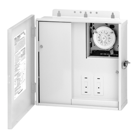
INSTALLATION - MODEL PF1103
1. Select the proper outdoor location for the
Freeze Protection Control and prepare the
necessary conduit run(s) required by the
installation layout.
2. Hang enclosure on a flat vertical surface or
other support, preferably next to the Switching
Device, using hardware
suitable for the purpose.
3. Properly terminate
conduits at both ends
and pull-in the
conductors as specified by the installation layout.
4. Select the appropriate wiring diagram (120 V.
or 240 V. installation) on page 3 or 4 of this
manual and make LINE and LOAD (Pump)
connections as shown. Wiring the Freeze
Control, first identify each lead by its color
then make wire connections by using wire
nuts. wiring the Time Switch, if it is Intermatic,
follow the diagram. Make connections to
terminal block as shown, see insert above for
Time Switch made prior to 1984 by Intermatic
or made by another manufacturer or it is an air
switch, first identify the LINE and LOAD
terminals of the control and wire the two
devices in Parallel.
Make sure the installation is properly grounded.
5. If the Freeze Protection Control is installed in
location, where it is exposed to direct sun
most of the day, extend 8 inches of the
copper capillary tube of the thermostat into an
open ended (plastic or metal) conduit, about
10 inches long, installed at bottom of the
enclosure. Handle capillary tube with care!
6. TEST INSTALLATION:
a. Turn the thermostat dial to its lowest setting
and place crushed ice (in plastic bag) inside
capillary coil of Thermostat.
b. Turn ON power to Control Panel, wait one
minute then slowly turn thermostat dial
counterclockwise until Filter Pump starts.
c. Turn power OFF to Control, remove ice,
check wiring, tighten terminal screws if
necessary, reinstall front plate.
d. Turn power ON to Control and set Time
Switch and the Thermostat, see
OPERATION instructions below.
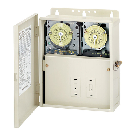
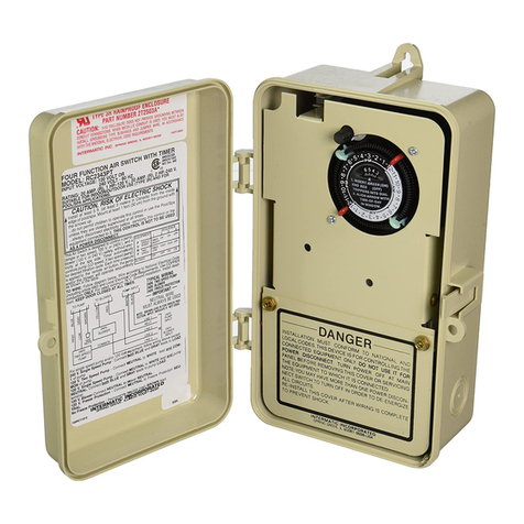
Install mechanism in any Intermatic Pool
Panel with only one Time Switch by snapping
it into the unused mounting bracket, furnished
with the Panel and follow steps 4 to 6 above.
PRESSURE PLATE
TERMINAL SCREW
MAKE SURE INSULATION
CLEARS PRESSURE PLATE
CONDUCTOR
TO SET THERMOSTAT, turn dial, pointing to desired temperature between 32˚F and 45˚F, marked on
the plate. Remember, many variables, such as the location of the Freeze Protection Control, the location
of equipment and the pool or spa, the location and insulation of the plumbing, etc., must be considered
before selecting the “turn ON” temperature of the Filter Pump. Your local pool service professional is the
best source of information. The Thermostat is factory set to turn OFF the Filter Pump when the ambient
temperature rises 5˚F above its set point.
TO SET TIME SWITCH, follow instructions inside Time Switch enclosure cover.
OPERATION
INSTALLATION - MODEL PF1103M
