Intermatic PA Series Manual
Other Intermatic Controllers manuals
Intermatic
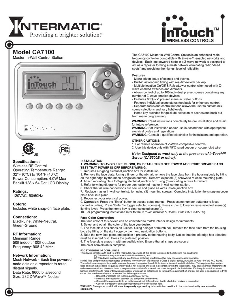
Intermatic InTouch CA7100 User manual
Intermatic
Intermatic PE103 Manual
Intermatic
Intermatic Lae AT1-5 Series User manual
Intermatic
Intermatic PE24GVA User manual
Intermatic
Intermatic EM1400 SERIES User manual
Intermatic
Intermatic HA07 User manual
Intermatic
Intermatic PE Series Manual

Intermatic
Intermatic HA07 Safety guide
Intermatic
Intermatic FREEZE SENTRY PF1103 Manual
Intermatic
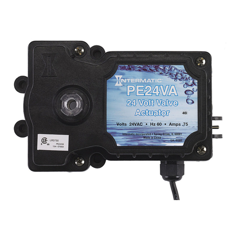
Intermatic PE24VA Manual
Intermatic
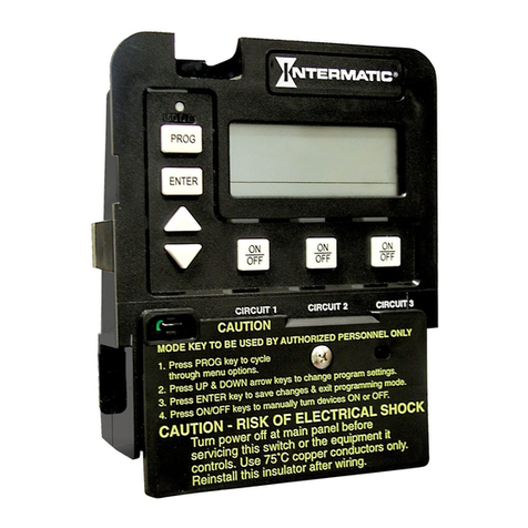
Intermatic P1353ME User manual
Intermatic
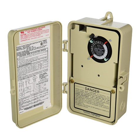
Intermatic RC2000 Series Manual
Intermatic
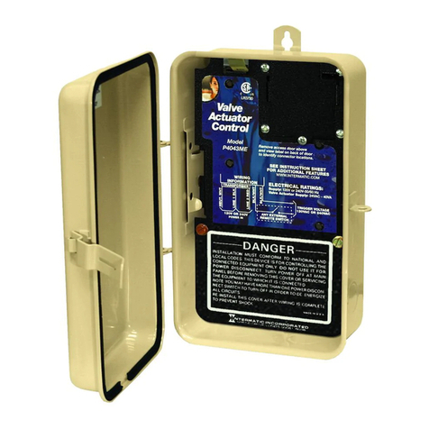
Intermatic PE140 User manual

Intermatic
Intermatic PE24VA Installation and operating instructions
Intermatic
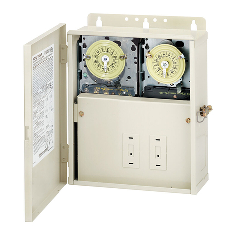
Intermatic T10604R Manual
Intermatic
Intermatic ReadySet PE24RSVA User manual
Intermatic
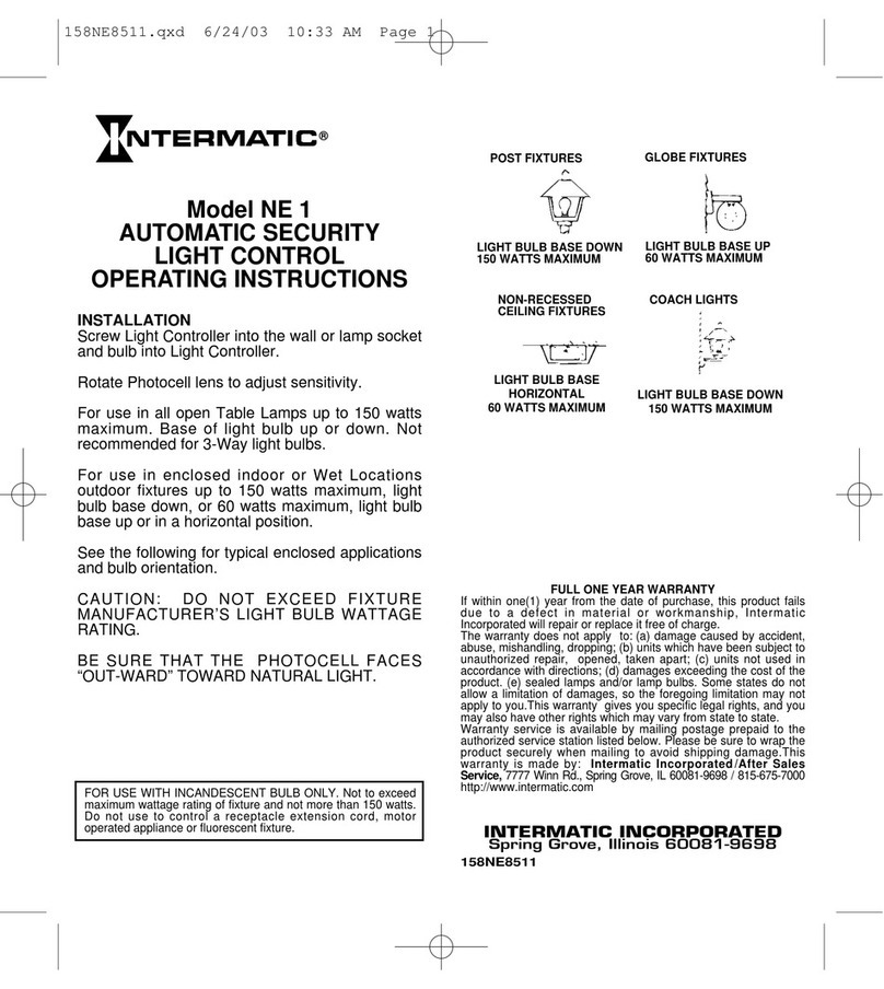
Intermatic NE 1 User manual
Intermatic
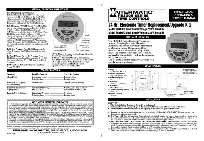
Intermatic PB313EK Service manual
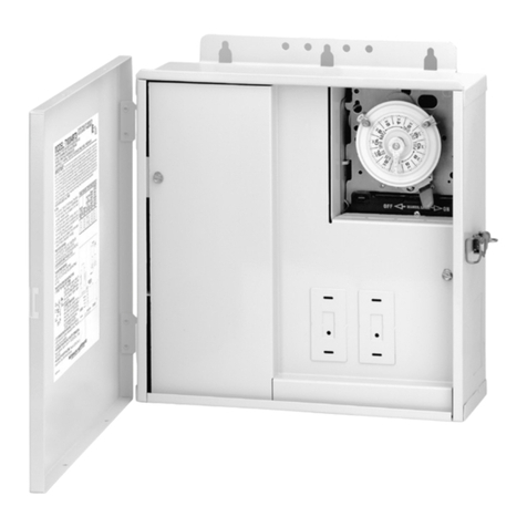
Intermatic
Intermatic T10000RT Series Manual
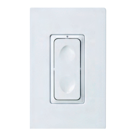
Intermatic
Intermatic InTouch CA5100 User manual
Popular Controllers manuals by other brands

Digiplex
Digiplex DGP-848 Programming guide

YASKAWA
YASKAWA SGM series user manual

Sinope
Sinope Calypso RM3500ZB installation guide

Isimet
Isimet DLA Series Style 2 Installation, Operations, Start-up and Maintenance Instructions

LSIS
LSIS sv-ip5a user manual

Airflow
Airflow Uno hab Installation and operating instructions


