Table of Contents
Page
TableOfContents .............................2
Introduction..................................3
Warning and General Safety Information . . . . . . . . . . .
Installation Tips & Useful Information . . . . . . . . . . . . .5
Step #1 Identify Connections & Voltage Selection . .6,7
Step #2 Installing The Shutter Bushing . . . . . . . . . . . .8
Step #3 Routing & Connecting Low Voltage
Accessories..................................9
Step # Snap In The Multipurpose Control . . . . . . . .10
Step #5 Installing Corrugated Tubing . . . . . . . . . .11,12
ModeTable .................................13
An Overview of the Multipurpose
Control Panel . . . . . . . . . . . . . . . . . . . . . . . . . .1 ,15
Step #6 Ratings, Wiring Schematics
and Mode Selection . . . . . . . . . . . . . . . . . . . . . . .16 – 22
Rating for All Modes . . . . . . . . . . . . . . . . .16
Mode 1 (Aux1, Aux2, Aux3) ................17
Mode 2 (Pump High, Pump Low, Aux3) ..........18
Mode 3 (Filter Pump, Aux2, Clear Pump) .........19
Mode (Pump High, Pump Low, Cleaner Pump) .....20
Mode 5 (Pump, Aux3) ....................21
SettingtheMode ....................22
Step#7 Setting The Time . . . . . . . . . . . . . . . . . . . . . .23
Step#8 Setting The ON/OFF Times . . . . . . . . . . . .2 ,27
Step#9 Setting The Firemen Switch Time . . . . . . . . .28
Step#10 Setting The Freeze Temperature . . . . . . . . .29
Runtime Definitions . . . . . . . . . . . . . . . . . . . . . . .30 – 32
Firemen Switch Runtime Display . . . . . . .30
Freeze Control Runtime Display . . . . . . . .31
Cleaner Pump Runtime Display . . . . . . . . .32
SpecialFeatures .........................33–36
Setting the Countdown Timer . . . . . . . . . .33
Clearing all ON/OFF Events . . . . . . . . . . . .3
Viewing Revision Level . . . . . . . . . . . . . . .35
Warranty ...................................36
23
IINNTTRROODDUUCCTTIIOONN
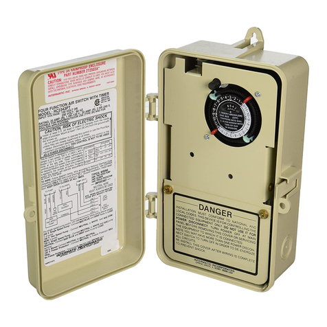
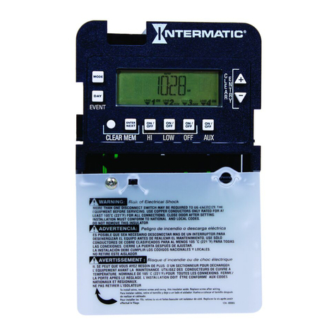
The ntermatic Multipurpose 24-Hour Control is an easy
to program three-circuit mechanism capable of automati-
cally switching loads according to a preset daily schedule
and providing control over a variety of different applica-
tions. This control is designed to switch resistive loads
up to 17 amps, and can handle single phase motor loads
up to 17 Full Load Amps (FLA) for each individual circuit.
ts unique preprogrammed (MODE) selections allow you
to customize your control from the simplest of applica-
tions such as lighting, heating, or air conditioning, to the
more sophisticated pool or spa pump and light applica-
tions. ts extended features list such as the freeze con-
trol sensor or remote control allows you to add on those
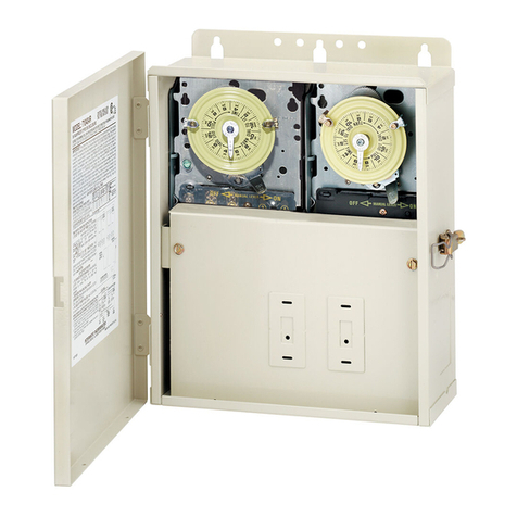
features at anytime. Designed as a mechanism, the
ntermatic multipurpose control can be installed in any
existing ntermatic panel or rain tight enclosure in the
industry today. We are confident you will find this control
to perform to your high expectations, and continue to
watch for new innovations from ntermatic nc.
IMPORTANT NOTE
This Owners Manual is designed to demonstrate the
installation and operating procedure for the new
Multipurpose Çontrol into any Intermatic panel. If
your Intermatic panel is designed with the new low
voltage raceway, the corrugated tubing included
with this control is not required to be installed.
Simply use the raceway in place of the tubing for
all low voltage accessories.
