Interpack HSD2000 XS II Series User manual
HSD2000 XS II 2”/ 3”
TAPE HEAD
UH088 / UH588
OPERATION MANUAL
&
PARTS LISTS
UDH10002 Rev. 0
This Manual Covers Tape Heads With Serial Numbers Starting
With H 088 or H 588
For All Other Serial Numbers, Contact Customer @800-474-8273

UDH10002 HSD 2000 XSII 2” / 3” Manual 2
UH088-UH588
OPERATION MANUAL
TABLE OF CONTENTS
OPERATION MANUAL ............................................................................... 2
TABLE OF CONTENTS ............................................................................................. 2
SERVICE INSTRUCTIONS ....................................................................................... 3
Service .................................................................................................................................... 3
Replacement Parts .................................................................................................................. 3
WARRANTY................................................................................................................. 4
DESCRIPTION OF TAPE HEADS............................................................................ 5
SAFETY ISSUES.......................................................................................................... 7
Safety Rules............................................................................................................................ 7
Safety Decal Location............................................................................................................. 8
SPECIFICATIONS....................................................................................................... 9
Dimensions ............................................................................................................................. 9
Tape Head Weight .................................................................................................................. 9
Operating Conditions.............................................................................................................. 9
Tape Requirements ............................................................................................................... 10
SET-UP PROCEDURES............................................................................................ 11
Receiving and Handling ....................................................................................................... 11
Tape Head Installation.......................................................................................................... 11
Tape Loading........................................................................................................................ 11
Tape Threading..................................................................................................................... 11
Tape Centering...................................................................................................................... 13
Tape Tension Adjustment..................................................................................................... 14
Clutch Roller Tension Adjustment ....................................................................................... 15
Front Leg Length Adjustment............................................................................................... 16
Rear Leg Length Adjustment................................................................................................ 17
Front Arm Compression Spring Tension Adjustment .......................................................... 18
Blade Replacement ............................................................................................................... 19
TROUBLESHOOTING ............................................................................................. 20
RECOMMENDED SPARE PARTS ......................................................................... 21
2” Model:.............................................................................................................................. 21
3” Model:.............................................................................................................................. 21
PARTS LIST ................................................................................................ 23

UDH10002 HSD 2000 XSII 2” / 3” Manual 3
UH088-UH588
SERVICE INSTRUCTIONS
Service
This is the manual for the Intertape HSD2000 XS II series Tape Head. It has been set up
and tested in our factory with Intertape brand tapes. If any problems occur when
operating this equipment and you desire a service call or phone consultation, call
Intertape Customer Service at 1-800-972-4675.
Please provide the customer service representative with the Tape Head model number
and serial number. If you have a technical question that does not require an immediate
response, you may fax it to 1-813-621-9680.
Replacement Parts
Order parts by item number, part name and quantity required. Replacement parts are
available from your Authorized Interpack Distributor. Should you require assistance
selecting the correct part, you may call:
Intertape Polymer Group
Interpack Machinery Division
9940 Currie Davis Drive, Suite 23B
Tampa, FL, 33619
Tel: 1-800-972-4675
Fax: 1-813-621-9680
MODEL:
SERIAL NUMBER:
DATE OF PURCHASE:

UDH10002 HSD 2000 XSII 2” / 3” Manual 4
UH088-UH588
WARRANTY
EQUIPMENT WARRANTY AND LIMITED REMEDY: The following warranty is made in lieu
of all other warranties, express or implied, including, but not limited to, the implied
warranty of merchantability, the implied warranty of fitness for a particular purpose, and
any implied warranty arising out of a course of dealing, a custom or usage of trade:
Intertape sells its HSD2000 XS II series Tape Heads with the following warranties:
1. The knife blades, springs and wipe down rollers will be free from all defects for a
period of ninety (90) days. A lifetime warranty is available after delivery with an
Annual Tape Agreement and completed Pioneering Protection Warranty form.
Contact your Intertape representative for further details.
2. All other HSD2000 XS II Tape Head parts will be free from all defects for one (1)
year after delivery.
If any part is proven defective within its warranty period, then the exclusive remedy and
Intertape's and the seller's sole obligation shall be, at Intertape's option, to repair or
replace the part, provided the defective part is returned immediately to Intertape's factory
or an authorized service station designated by Intertape.
A part will be presumed to have become defective after its warranty period unless the
part is received or Intertape is notified of the problem no later than five (5) calendar days
after the warranty period.
If Intertape is unable to repair or replace the part within a reasonable time, then Intertape,
at its option, will replace the equipment or refund the purchase price. Intertape shall have
no obligation to install the repaired or replacement part.
Intertape shall have no obligation to provide or pay for the labor required to install the
repaired or replacement part. Intertape shall have no obligation to repair or replace (1)
those parts failing due to operator misuse, carelessness, or due to any accidental cause
other than equipment failure, or (2) parts failing due to inadequate cleaning, improper
operating environment, improper utilities or operator error.
LIMITATION OF LIABILITY: Intertape and seller shall not be liable for direct, indirect,
special, incidental or consequential damages based upon breach of warranty, breach of
contract, negligence, strict liability or any other legal theory.
The foregoing Equipment Warranty and Limited Remedy and Limitation of Liability may
be changed only by written agreement signed by authorized officers of Intertape and
seller.

UDH10002 HSD 2000 XSII 2” / 3” Manual 5
UH088-UH588
DESCRIPTION OF TAPE HEADS
Figure 1
The HSD2000 XS II Tape Head (figure1) is designed to apply Intertape brand pressure
sensitive carton sealing tape to the top and bottom center seam of regular slotted
corrugated cartons. It is easy to set-up and to operate. The model shown in this manual is
a standard 2” Tape Head. Also available are the mirror models 2” or 3” wide.
MIRROR MODEL
STANDARD MODEL

UDH10002 HSD 2000 XSII 2” / 3” Manual 6
UH088-UH588
How the Tape Head Works
MANDREL
PEEL OFF ARM
MANDREL ARM
AUXILIARY ARM
REAR ARM
FRONT ARM
KNIFE ARM
CLUTCH
Figure 2
When the operator installs a new tape roll on the mandrel, the Tape Head is ready to
operate. The tape leg catches the front side of the incoming carton. The tape is then
applied to the top or bottom of the carton with pressure provided by the front arm. When
the carton’s rear edge advances passed the front arm and knife arms, both arms are
snapped back into place and the knife cuts the tape. As the carton exits the tape head the
rear arm snaps back into place wiping down the rear leg of the tape.

UDH10002 HSD 2000 XSII 2” / 3” Manual 7
UH088-UH588
SAFETY ISSUES
Safety Rules
The Tape Head has been designed to be extremely safe for operators and bystanders.
Nevertheless, accidents can happen. Therefore, it is important to follow safe work
practices. The operator must read and follow these safety rules when working on or near
the device.
•Read this manual and its safety instructions thoroughly before operating.
•Only trained personnel are to operate, adjust or service the equipment.
•Shut off machine in case of emergency.
•Never wear loose clothing, jewelry or tie when operating machine.
•Wear safety glasses.
•All covers and guards must be in place before operating.
•Stay clear of moving parts which may shear and cut.
•Never operate the Tape Head with the knife flipper guard removed.
•Do not modify the equipment in any way. Unauthorized modification may impair
the function and/or safety and could affect the life of the equipment.
•Carefully read all safety decals on the Tape Head. If they are damaged and
become illegible, replace them immediately. (See section 2.2, figure 4 for safety
decal location).
•Use caution when handling knife. Knife blade is very sharp. Do not touch blade
with bear hand.
Figure 3
CAUTION!
Very Sharp!

UDH10002 HSD 2000 XSII 2” / 3” Manual 8
UH088-UH588
Safety Decal Location
The figure below shows where the safety decal is located on the equipment. Replace
decal if it is absent or becomes illegible. Replacement decals can be found in the Parts
section of this manual.
WARNING
Sharp
Cutting
WARNING
Sharp
Cutting
Blade
Figure 4

UDH10002 HSD 2000 XSII 2” / 3” Manual 9
UH088-UH588
SPECIFICATIONS
Dimensions
19,0
22,560
24,250
1,114
1,00
7,273,4
8,48
20,35
10,42
3" version
5,358 2" v.
4,358
Figure 5
Tape Head Weight
Tape Head weight when shipped:
2” model: 29 lbs (13 Kg)
3” model: 32 lbs (14.5 Kg)
Operating Conditions
Use in a dry, relatively clean environment at 40º to 105º F (5º to 40º C) with clean dry
cartons.
Note: The Tape Head should never be washed down or subjected to conditions causing
condensation on components.

UDH10002 HSD 2000 XSII 2” / 3” Manual 10
UH088-UH588
Tape Requirements
1. Type:
Intertape brand Pressure Sensitive Carton Sealing Tape.
2. Tape Width:
1!to 2 inch wide tape maximum for the 2” model.
2!to 3 inch wide tape maximum for the 3” model.
3. Tape roll diameter:
Maximum of 16 inches.
4. Tape Application Leg Length:
From 2 3/8” to 2 "”.

UDH10002 HSD 2000 XSII 2” / 3” Manual 11
UH088-UH588
SET-UP PROCEDURES
Receiving and Handling
All contents must be verified upon reception. The following items must be in the box:
HSD2000 XS II Tape Head with mandrel arm dismounted, this brochure, 4 mounting
adaptors with M6 socket head cap screws, one extra blade flip-guard torsion spring, two
knife arm extension springs, two compression springs and two extension springs for the
rear arm.
Note: After unpacking the Tape Head, look for any damage that may have occurred
during shipping. Should the Tape Head be damaged, file a claim with the
transport company and notify your Intertape representative.
Tape Head Installation
The tape heads require the installation of adapters to mount into the machines. Different
length adapters are supplied with the 2 inch and 3 inch versions of the tape head and
other lengths are available. For non-standard mounting adaptors consult technical
support.
Tape Loading
WARNING! TURN OFF ELECTRICAL POWER SUPPLY AND DISCONNECT THE POWER
CORD FROM THE ELECTRICAL SUPPLY BEFORE BEGINNING TO WORK ON
THE TAPE HEADS OR TO LOAD TAPE. IF POWER CORDS ARE NOT
DISCONNECTED,SEVERE INJURY TO PERSONNEL COULD RESULT.
Push the roll of tape onto the mandrel with the adhesive side up (refer to Threading
Diagram under Tape Threading in this manual) until the core seats against the mandrel
flange. This ensures the tape will be aligned when feeding into the tape head.
Tape Threading
WARNING!THE KNIFE CONTAINED IN THE TAPE HEAD IS EXTREMELY SHARP. USE
CAUTION WHEN REMOVING THE BLADE GUARD AND THREADING THE TAPE
TO AVOID PERSONNEL INJURY.
UDH10002 HSD 2000 XSII 2” / 3” Manual 12
UH088-UH588
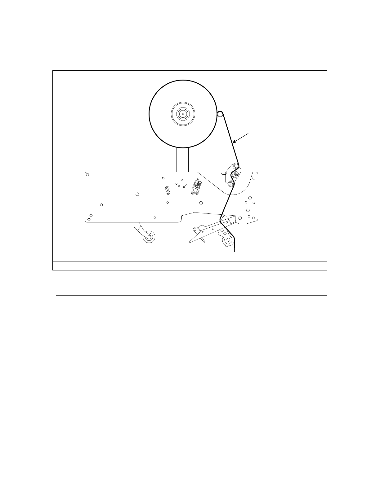
Figure 6 shows how the tape must be threaded. You can also refer to the diagram on the
Tape Head plate for threading instructions. Use a knife to cut tape leg.
ADHESIVE SIDE
Figure 6
Note: Plastic blade guard must be removed before operating tape head.

UDH10002 HSD 2000 XSII 2” / 3” Manual 13
UH088-UH588
Tape Centering
Should the tape require centering, the tape mandrel can be adjusted in and out. First
loosen the 1” hex jam nut, then adjust the shaft in or out as required using a flat-head
screwdriver. When the tape is centered, tighten the jam nut.
Figure 7

UDH10002 HSD 2000 XSII 2” / 3” Manual 14
UH088-UH588
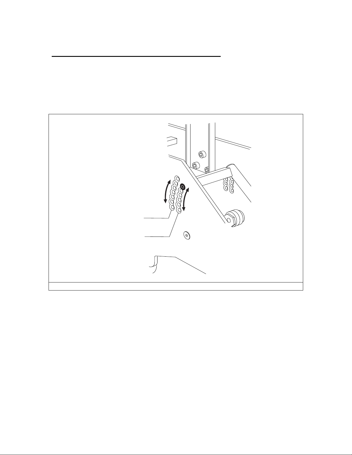
Tape Tension Adjustment
The roll of tape should turn with slight resistance provided by the mandrel. Mandrel
tension may be adjusted by turning the mandrel nut (As shown in Figure 8). Turn
clockwise for more tension or counter clockwise to loosen the tension.
Figure 8
Loosen
Mandrel
Nut

UDH10002 HSD 2000 XSII 2” / 3” Manual 15
UH088-UH588
Clutch Roller Tension Adjustment
The clutch roller should be adjusted for very little tension. Use lock-nut to adjust tension
as shown in figure 9.
Figure 9

UDH10002 HSD 2000 XSII 2” / 3” Manual 16
UH088-UH588
Front Leg Length Adjustment
To adjust the length of the front leg, slide the clutch forward or backward until leg
length is satisfactory. To move the clutch, first loosen the two adjustment screws as
shown below. Retighten screws once clutch is adjusted.
ADJUSTMENT
SCREWS
SHORTER FRONT LEG
LONGER FRONT LEG
Figure 10

UDH10002 HSD 2000 XSII 2” / 3” Manual 17
UH088-UH588
Rear Leg Length Adjustment
To adjust the length of the rear tape leg, remove the four (4) knife arm screws and adjust
length by moving the knife arm forward or backward, as shown in figure 11.
REMOVE SCREWS
TO SLIDE KNIFE ARM
LONGER
REAR LEG
SHORTER
REAR LEG
Figure 11
UDH10002 HSD 2000 XSII 2” / 3” Manual 18
UH088-UH588
Front Arm Compression Spring Tension Adjustment
This adjustment is done to insure gradual reduction in force as the roller travels up on the
end of the carton panel to eliminate carton crushing and dog earring as the front arm’s
roller turns around the corner onto the center seam. There are two sets of adjustment
holes, one for less pressure and one for more pressure. The pressure (or force) can also be
adjusted by moving the adjustment screw up or down as shown in figure 12.
+
-
+
-
LESS PRESSURE
SETTINGS
MORE PRESSURE
SETTINGS
LESS
PRESSURE
MORE
PRESSURE
Figure 12

UDH10002 HSD 2000 XSII 2” / 3” Manual 19
UH088-UH588
Blade Replacement
WARNING!THE BLADE CONTAINED IN THE TAPE HEAD IS EXTREMELY SHARP. USE
CAUTION WHEN OPENING THE BLADE GUARD AND REPLACING THE BLADE
TO AVOID PERSONAL INJURY.
To replace the blade:
1. Open the blade flipper guard
2. Remove the two (2) button head screws
3. Remove and replace the blade. Make sure the flat part of the blade is facing the
back plate
4. Ascertain that the blade flipper guard returns to cover the knife blade.
BLADE
SCREWS
BLADE
GUARD
Figure 13

UDH10002 HSD 2000 XSII 2” / 3” Manual 20
UH088-UH588
TROUBLESHOOTING
The Tape Head requires minimum maintenance. Simply replace the blade regularly to
provide clean tape leg cuts.
PROBLEM POSSIBLE CAUSE AND SOLUTION
Rear leg stretched or not cut Blade does not cut. Replace blade.
The tape is overstretched by having too
much friction on the mandrel or front arm
roller.
Rear leg is not properly wiped down
Dirt on rear arm causing friction. Clean or
replace roller.
Dog ears on carton
Lower pressure by adjusting tension on the
front arm compression springs (pivot
assembly) as shown in Figure 12.
Table of contents
Other Interpack Industrial Equipment manuals

Interpack
Interpack CE-12P User manual

Interpack
Interpack USA 2024-SB User manual

Interpack
Interpack RSA 20-B User manual

Interpack
Interpack USA 2024-SB DH User manual

Interpack
Interpack CE-12P User manual

Interpack
Interpack ipg RSA 2625-TB User manual

Interpack
Interpack HSD2000 ET II RC User manual

Interpack
Interpack ETII+ LD User manual


